Fagor CNC 8055 for milling machines Owner's manual

Type
Owner's manual
CNC
8055
Educational
Ref. 1107
Ref.1107
·3·

Educational CNC
1 Introduction to the educational model
The educational CNC has a keyboard specially designed for milling and turning applications.
The following material is supplied with the CNC:
KeyCF memory configured to work in mill or lathe mode.
The KeyCF must be configured with the following folders
Vers: Contains the latest software version for mill and lathe.
backup mill-fresa: Contains all the parameters, tables, programs, etc. of the mill model.
backup lathe-torno: Contains all the parameters, tables, programs, etc. of the lathe model.
CAN - Ethernet communications board.
Universal 24 V DC power supply and cable for connecting to the CNC.
Educational CNC support.
A CD-ROM containing the manuals for the Mill and Lathe models.
With the educational CNC, it is possible to edit, program and simulate all the CNC features, but the
axes cannot be moved physically.
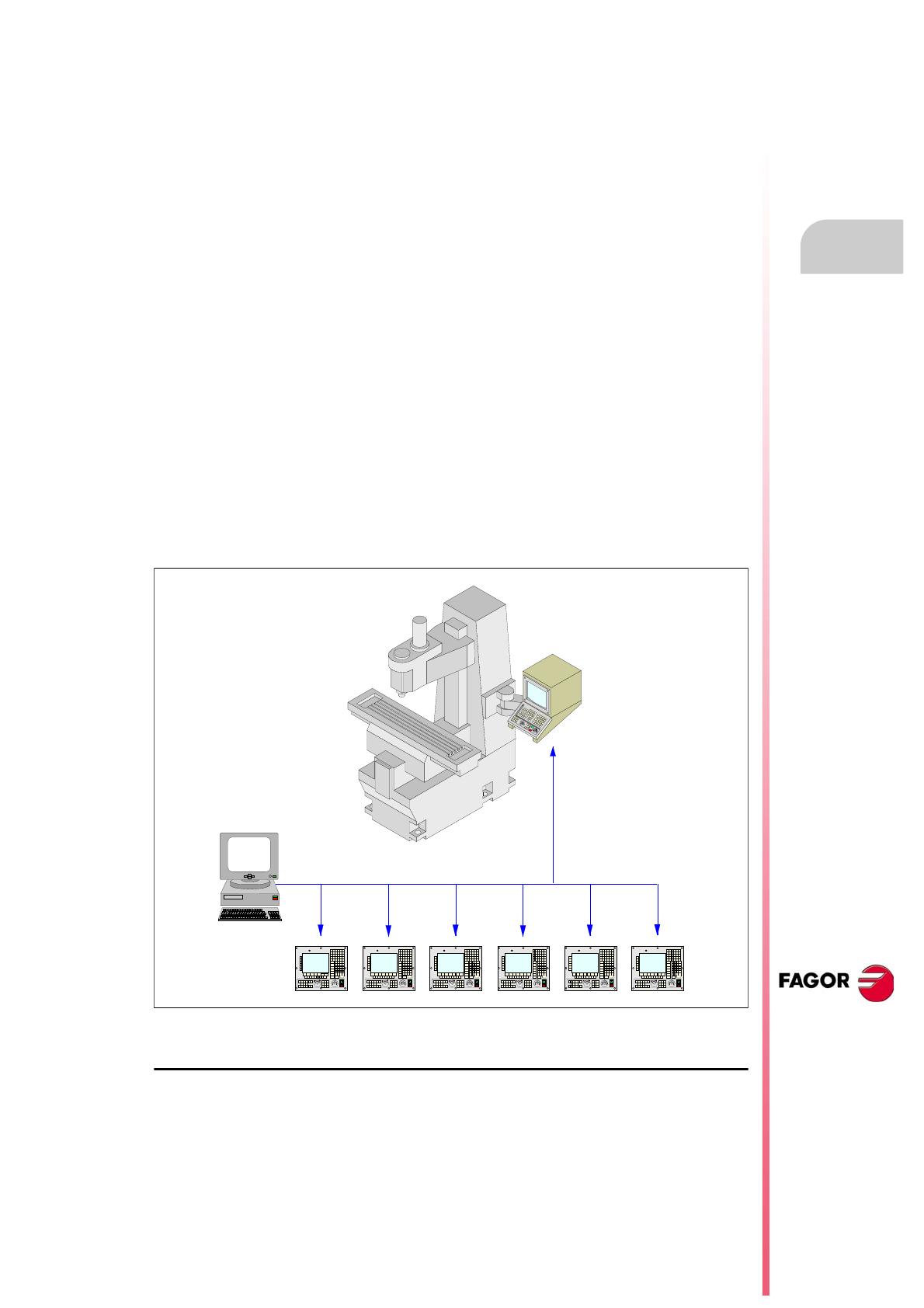
The educational CNC can communicate with another Fagor CNC through the RS232 serial line or
Ethernet for transferring part-programs. This way, a program generated and simulated at the
educational CNC may be executed on a machine that has a Fagor CNC.
Via Ethernet, it is also possible to communicate one or several educational CNC-s with a PC and
with a Fagor CNC so, from the PC and using WinDNC it is possible to control or display all the
educational CNC's.
Educational CNC support
The Educational CNC has a tree-piece support for putting it on the table. These parts are supplied
in a separate box with the power supply and they must be assembled. See "6 CNC support
assembling sequence" on page 10.
FAGOR
0
2
4
10
20
30
40
50
60
70
80
90
100
110
120
FEED %SPIND LE
JOG
100
10
1
1
10100
1000
10000
RS232C
ETHERNET
FAGOR
0
2
4
10
20
30
40
50
60
70
80
90
100
110
120
FEED %SPIND LE
JOG
100
10
1
11010 0
1000
10000
FAGOR
0
2
4
10
20
30
40
50
60
70
80
90
100
110
120
FEED %SPIND LE
JOG
100
10
1
1
10100
1000
10000
FAGOR
0
2
4
10
20
30
40
50
60
70
80
90
100
110
120
FEED %SPIND LE
JOG
100
10
1
1
10100
1000
10000
FAGOR
0
2
4
10
20
30
40
50
60
70
80
90
100
110
120
FEED %SPIND LE
JOG
100
10
1
1
10100
1000
10000
FAGOR
0
2
4
10
20
30
40
50
60
70
80
90
100
110
120
FEED %SPIND LE
JOG
100
10
1
1
10100
1000
10000
PC
Ref.1107
·4·

Educational CNC
2 Connectors and connection
Power supply
A universal 24 V DC power supply is provided together with these support pieces.
This power supply is attached to the side support of the CNC. Once the three pieces of the CNC
support have been assembled, connect the supply cable of the power supply to the CNC.
Connectors
The rear panel has:
(A) Power supply.
(B) Ground connection.
(C) Communications board
(D) To connect the pendrive or an USB extension cable.
X1 For RS232 serial line connection.
X2 For digital I/O connection (I1 through I16 and O1 through O8).
X3 For probe connection.
X4 For analog spindle connection.
X5 For electronic handwheel connection.
X6 For Operator Panel connection.
X1
X2
X3
X4 X5
X6
D
C
A
B
+24V
0V
The installation manual describes all these connectors.
By executing PLC programs, it is possible to use the 16 digital inputs and 8 digital
outputs (of 500 mA) of connector X2.
i
Ref.1107
·5·

Educational CNC
Communications board
Ethernet
Ethernet connection to integrate the CNC into the computer network. The Ethernet card has an
RJ-45 connector and two LED's that inform on the status of the connection.
Use a standard shielded 10BASE-T cable for this connection. It must not be longer than 100
meters.
CAN connector
Not being used.
Connection of the USB extension cable supplied by Fagor
The USB extension cable with the CNC.
1. Connect the extension cable as shown in the figure while the CNC is off.
2. Once the extension cable has been connected, you may use the USB of on the front of the
keyboard while the CNC is ON.
Red LED Blinks while transmitting data.
Green LED On while connected to the network.
X1
CAN connector Ethernet
X1
X2 X3 X4 X5 X6
+24V
0V
Type A USB
connector
Type B USB
connector.
FAGOR
0
2
4
10
20
30
40
50
60
70
80
90
100
110
120
FEED %
SPINDLE
JOG
100
10
1
1
10
100
1000
10000
USB connector
of the keyboard
Ref.1107
·6·

Educational CNC
3 CNC setup
Every time the CNC is turned on, it does an automatic Restore. The CNC does a Restore depending
on the software version installed (mill or lathe); i.e. either from either the "backup mill-fresa" folder
or from the "backup lathe-torno" folder.
3.1 Updating the milling software
To change the software (from lathe to mill) at the CNC, proceed as follows:
Press the "M" key for 3 seconds.
When pressing the "M" key, the CNC sets variable MODEL = 0 and does a SHIFT-RESET. Then,
it does a Restore from the "Backup mill-fresa" folder so the mill mode is properly set up
(programs, parameters, tables, etc.).
3.2 Updating the lathe software
To change the software (from mill to lathe) at the CNC, proceed as follows:
Press the "L" key for 3 seconds.
When pressing the "L" key, the CNC sets variable MODEL = 1 and does a SHIFT-RESET. Then,
it does a Restore from the "Backup lathe-torno" folder so the lathe mode is properly set up
(programs, parameters, tables, etc.).
The software updating process may be carried out from a PC using WinDnc (writing
MODEL = 0 and generating a SHIFT-RESET). This makes it possible to update the
software in several CNC's at the same time.
i
The software updating process may be carried out from a PC using WinDnc (writing
MODEL = 1 and generating a SHIFT-RESET). This makes it possible to update the
software in several CNC's at the same time.
i
Ref.1107
·7·

Educational CNC
4 Safety backup. Backup - Restore
Backup configuration
To do a backup in any folder of the hard disk or in a pendrive, follow these steps:
Access the "Status" mode and select the "CNC / Backup" option.
Select the folder for the backup.
Select the desired options:
OEM data: Programs
Parameters and tables
Screens (pages) and symbols
Servo drive parameters
User data: Programs
Press the "Begin Backup" softkey.
Restore configuration
To do a Restore, follow these steps:
Access the "Status" mode and select the "CNC / Restore" option.
Use the explorer to select the desired folder.
Select the desired options:
OEM data: Programs
Parameters and tables
Screens (pages) and symbols
Servo drive parameters
User data: Programs
Press the "Begin Restore" softkey.
When saving any parameter from any particular table onto the hard disk, it is saved
in the "backup mill-fresa" folder or "backup lathe-torno" folder
i
If you change the CNC configuration or add new part-programs, you will have to do
a backup in the same folder if you wish to use the latest configuration the next time
you do a restore.
For these changes to be maintained at very CNC power-up, the backup must be done
in the "backup mill-fresa" or "backup lathe-torno" folder.
i
Ref.1107
·8·

Educational CNC
5 Configure the CNC inside an Ethernet network
The Ethernet option permits configuring the CNC as another node within the local area network.
This makes it possible to communicate with other PC's through WindDNC, for example to transfer
files.
It is configured at the CNC through the machine parameters for Ethernet.
Connection to a PC through WinDNC.
The PC operative system must be Windows
®
and it must have the WinDNC software (V5.02 or
newer). The possible connections are:
Connection from a PC:
The connection may be initiated at any PC and addressed to any CNC. Two PC's cannot be
connected to each other.
To establish the connection, the WinDNC allows the user to enter the CNC's IP address to be
used for the connection.
Connection from a CNC:
The connection is always addressed to the DNC server. The DNC server is defined in the
machine parameter "IPWDNC".
Several PC's and CNC's may be network connected simultaneously using WinDNC. If several
WinDNC initiate an operation accessing a CNC, the commands are processed one by one while
the rest of the WinDNC's wait.
Machine parameters for configuring the CNC as another node of the
network
DNCEACT (P22)
DNC number to be used by Ethernet.
IPTYPE (P23)
Reserved. It must be set to "0".
DIRIP (P24)
CNC's IP address.
It requires [SHIFT]+[RESET] to validate the parameter.
The WinDNC version that supports Ethernet is V5.02 or newer.
i
Possible values:
0 There is no active DNC associated with Ethernet.
1 DNC 1 associated with Ethernet.
2 DNC 2 associated with Ethernet. The RS-232 serial line is disabled.
By default: 1
Possible values: Four numbers between 0 and 255 separated by dots.
By default: 0.0.0.0 (the network is not activated).
Ref.1107
·9·

Educational CNC
NETMASK (P25)
Network mask.
It requires [SHIFT]+[RESET] to validate the parameter.
IPWDNC (P27)
WinDNC server's IP address. The WinDNC server is the external device to connect with via DNC.
This device may be a CNC, or a PC with WinDNC.
Defining it as 0.0.0.0 does not allow transferring from the CNC, but it is possible from the PC.
It requires [SHIFT]+[RESET] to validate the parameter.
Possible values: Four numbers between 0 and 255 separated by dots.
By default: 0.0.0.0
Possible values: Four numbers between 0 and 255 separated by dots.
By default: 0.0.0.0
Ref.1107
·10·

Educational CNC
6 CNC support assembling sequence
1. Fasten the power supply is attached to the right support.
2. Fasten the right CNC support with two M4x10 screws and two washers.
It is important to follow the mounting sequence.
M4x10 screws.
Power supply.
Ref.1107
·11·

Educational CNC
3. Fasten the left CNC support with two M4x10 screws and two washers.
4. Fasten the top lid to the CNC support with three M4x10 screws and three washers.
5. Fasten the top lid to the side supports with two M4x20 screws and two washers.
6. Power supply connection.
M4x10 screws.
M4x10 screws.
M4x20 screws.
Network connector.
Power supply
connector for
the CNC.
Use the cable
provided by
Fagor to
connect it to the
CNC voltage
supply.
CNC voltage supply.
Ref.1107
·12·

Educational CNC
  • Page 1 1
  • Page 2 2
  • Page 3 3
  • Page 4 4
  • Page 5 5
  • Page 6 6
  • Page 7 7
  • Page 8 8
  • Page 9 9
  • Page 10 10
  • Page 11 11
  • Page 12 12

Fagor CNC 8055 for milling machines Owner's manual

Type
Owner's manual

Ask a question and I''ll find the answer in the document

Finding information in a document is now easier with AI