
1
2
United Kingdom
en
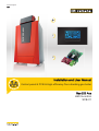
Installation and User Manual
Control panel & PCB & High-efficiency floor-standing gas boiler
Gas 220 Ace
HMI S-control
SCB-01

Dear Customer,
Thank you very much for buying this appliance.
Please read through the manual carefully before using the product, and keep it in a safe place for later reference. In order to
ensure continued safe and efficient operation we recommend that the product is serviced regularly. Our service and customer
service organisation can assist with this.
We hope you enjoy years of problem-free operation with the product.

Contents
1 Safety . . . . . . . . . . . . . . . . . . . . . . . . . . . . . . . . . . . . . . . . . . . . . . . . . . . . . . . . . . . . . . . . . . . . . . . . . . . . . . . . . . . . . . . . . . . . 4
1.1 Liabilities . . . . . . . . . . . . . . . . . . . . . . . . . . . . . . . . . . . . . . . . . . . . . . . . . . . . . . . . . . . . . . . . . . . . . . . . . . . . . . . . . . . . . 4
1.1.1 Manufacturer's liability . . . . . . . . . . . . . . . . . . . . . . . . . . . . . . . . . . . . . . . . . . . . . . . . . . . . . . . . . . . . . . . . . . . 4
1.1.2 Installer's liability . . . . . . . . . . . . . . . . . . . . . . . . . . . . . . . . . . . . . . . . . . . . . . . . . . . . . . . . . . . . . . . . . . . . . . . 4
1.1.3 User's liability . . . . . . . . . . . . . . . . . . . . . . . . . . . . . . . . . . . . . . . . . . . . . . . . . . . . . . . . . . . . . . . . . . . . . . . . . .4
2 About this manual . . . . . . . . . . . . . . . . . . . . . . . . . . . . . . . . . . . . . . . . . . . . . . . . . . . . . . . . . . . . . . . . . . . . . . . . . . . . . . . . . . . 6
2.1 Symbols used in the manual . . . . . . . . . . . . . . . . . . . . . . . . . . . . . . . . . . . . . . . . . . . . . . . . . . . . . . . . . . . . . . . . . . . . . .6
3 Description of the product . . . . . . . . . . . . . . . . . . . . . . . . . . . . . . . . . . . . . . . . . . . . . . . . . . . . . . . . . . . . . . . . . . . . . . . . . . . . . 7
3.1 Control panel description . . . . . . . . . . . . . . . . . . . . . . . . . . . . . . . . . . . . . . . . . . . . . . . . . . . . . . . . . . . . . . . . . . . . . . . . 7
3.1.1 What each key means . . . . . . . . . . . . . . . . . . . . . . . . . . . . . . . . . . . . . . . . . . . . . . . . . . . . . . . . . . . . . . . . . . . 7
3.1.2 Meaning of the symbols on the display . . . . . . . . . . . . . . . . . . . . . . . . . . . . . . . . . . . . . . . . . . . . . . . . . . . . . . 7
3.2 Description of the SCB-01 PCB . . . . . . . . . . . . . . . . . . . . . . . . . . . . . . . . . . . . . . . . . . . . . . . . . . . . . . . . . . . . . . . . . . . 8
4 User instructions . . . . . . . . . . . . . . . . . . . . . . . . . . . . . . . . . . . . . . . . . . . . . . . . . . . . . . . . . . . . . . . . . . . . . . . . . . . . . . . . . . . . 9
4.1 Use of the control panel . . . . . . . . . . . . . . . . . . . . . . . . . . . . . . . . . . . . . . . . . . . . . . . . . . . . . . . . . . . . . . . . . . . . . . . . . 9
4.1.1 Browsing in the menus . . . . . . . . . . . . . . . . . . . . . . . . . . . . . . . . . . . . . . . . . . . . . . . . . . . . . . . . . . . . . . . . . . 9
4.2 Setting the language and time . . . . . . . . . . . . . . . . . . . . . . . . . . . . . . . . . . . . . . . . . . . . . . . . . . . . . . . . . . . . . . . . . . . 10
4.2.1 Setting the language . . . . . . . . . . . . . . . . . . . . . . . . . . . . . . . . . . . . . . . . . . . . . . . . . . . . . . . . . . . . . . . . . . . 10
4.2.2 Setting the time and date . . . . . . . . . . . . . . . . . . . . . . . . . . . . . . . . . . . . . . . . . . . . . . . . . . . . . . . . . . . . . . . .10
4.3 Changing the central heating flow temperature . . . . . . . . . . . . . . . . . . . . . . . . . . . . . . . . . . . . . . . . . . . . . . . . . . . . . . 11
4.4 Changing the DHW temperature . . . . . . . . . . . . . . . . . . . . . . . . . . . . . . . . . . . . . . . . . . . . . . . . . . . . . . . . . . . . . . . . . .12
4.5 Setting the Timer Program . . . . . . . . . . . . . . . . . . . . . . . . . . . . . . . . . . . . . . . . . . . . . . . . . . . . . . . . . . . . . . . . . . . . . . 12
4.6 Changing user parameters . . . . . . . . . . . . . . . . . . . . . . . . . . . . . . . . . . . . . . . . . . . . . . . . . . . . . . . . . . . . . . . . . . . . . . 14
5 Installer instructions . . . . . . . . . . . . . . . . . . . . . . . . . . . . . . . . . . . . . . . . . . . . . . . . . . . . . . . . . . . . . . . . . . . . . . . . . . . . . . . . .16
5.1 Changing installer parameters . . . . . . . . . . . . . . . . . . . . . . . . . . . . . . . . . . . . . . . . . . . . . . . . . . . . . . . . . . . . . . . . . . . 16
5.2 Adjusting advanced parameters . . . . . . . . . . . . . . . . . . . . . . . . . . . . . . . . . . . . . . . . . . . . . . . . . . . . . . . . . . . . . . . . . . 17
5.3 Carrying out an auto-detect . . . . . . . . . . . . . . . . . . . . . . . . . . . . . . . . . . . . . . . . . . . . . . . . . . . . . . . . . . . . . . . . . . . . . 18
5.4 Restoring to factory settings . . . . . . . . . . . . . . . . . . . . . . . . . . . . . . . . . . . . . . . . . . . . . . . . . . . . . . . . . . . . . . . . . . . . . 18
5.5 Chimney sweep mode (forced full load or part load) . . . . . . . . . . . . . . . . . . . . . . . . . . . . . . . . . . . . . . . . . . . . . . . . . . 19
5.6 Connected control PCBs . . . . . . . . . . . . . . . . . . . . . . . . . . . . . . . . . . . . . . . . . . . . . . . . . . . . . . . . . . . . . . . . . . . . . . . .20
5.7 Activating the manual mode menu . . . . . . . . . . . . . . . . . . . . . . . . . . . . . . . . . . . . . . . . . . . . . . . . . . . . . . . . . . . . . . . . 20
5.8 Shutdown . . . . . . . . . . . . . . . . . . . . . . . . . . . . . . . . . . . . . . . . . . . . . . . . . . . . . . . . . . . . . . . . . . . . . . . . . . . . . . . . . . . 21
5.8.1 Switching off the central heating . . . . . . . . . . . . . . . . . . . . . . . . . . . . . . . . . . . . . . . . . . . . . . . . . . . . . . . . . . 21
5.8.2 Switching off DHW production . . . . . . . . . . . . . . . . . . . . . . . . . . . . . . . . . . . . . . . . . . . . . . . . . . . . . . . . . . . . 21
5.9 Reading out the Counter menu . . . . . . . . . . . . . . . . . . . . . . . . . . . . . . . . . . . . . . . . . . . . . . . . . . . . . . . . . . . . . . . . . . .21
5.10 Reading out current values . . . . . . . . . . . . . . . . . . . . . . . . . . . . . . . . . . . . . . . . . . . . . . . . . . . . . . . . . . . . . . . . . . . . . . 22
5.11 Status and Sub-status . . . . . . . . . . . . . . . . . . . . . . . . . . . . . . . . . . . . . . . . . . . . . . . . . . . . . . . . . . . . . . . . . . . . . . . . . .22
6 Installation . . . . . . . . . . . . . . . . . . . . . . . . . . . . . . . . . . . . . . . . . . . . . . . . . . . . . . . . . . . . . . . . . . . . . . . . . . . . . . . . . . . . . . . . 23
6.1 Electrical connections . . . . . . . . . . . . . . . . . . . . . . . . . . . . . . . . . . . . . . . . . . . . . . . . . . . . . . . . . . . . . . . . . . . . . . . . . . 23
6.1.1 Connecting status notifications . . . . . . . . . . . . . . . . . . . . . . . . . . . . . . . . . . . . . . . . . . . . . . . . . . . . . . . . . . . 23
6.1.2 Connecting 0–10 V output . . . . . . . . . . . . . . . . . . . . . . . . . . . . . . . . . . . . . . . . . . . . . . . . . . . . . . . . . . . . . . . 23
7 Operation . . . . . . . . . . . . . . . . . . . . . . . . . . . . . . . . . . . . . . . . . . . . . . . . . . . . . . . . . . . . . . . . . . . . . . . . . . . . . . . . . . . . . . . . .24
7.1 Setting the heating curve . . . . . . . . . . . . . . . . . . . . . . . . . . . . . . . . . . . . . . . . . . . . . . . . . . . . . . . . . . . . . . . . . . . . . . . 24
7.2 Cascade control . . . . . . . . . . . . . . . . . . . . . . . . . . . . . . . . . . . . . . . . . . . . . . . . . . . . . . . . . . . . . . . . . . . . . . . . . . . . . . 24
8 Settings . . . . . . . . . . . . . . . . . . . . . . . . . . . . . . . . . . . . . . . . . . . . . . . . . . . . . . . . . . . . . . . . . . . . . . . . . . . . . . . . . . . . . . . . . . 26
8.1 List of parameters . . . . . . . . . . . . . . . . . . . . . . . . . . . . . . . . . . . . . . . . . . . . . . . . . . . . . . . . . . . . . . . . . . . . . . . . . . . . . 26
8.1.1 Description of the parameters - SCB-01 . . . . . . . . . . . . . . . . . . . . . . . . . . . . . . . . . . . . . . . . . . . . . . . . . . . . 26
8.2 List of measured values . . . . . . . . . . . . . . . . . . . . . . . . . . . . . . . . . . . . . . . . . . . . . . . . . . . . . . . . . . . . . . . . . . . . . . . . 27
8.2.1 Counters - SCB-01 . . . . . . . . . . . . . . . . . . . . . . . . . . . . . . . . . . . . . . . . . . . . . . . . . . . . . . . . . . . . . . . . . . . . 27
8.2.2 Signals - SCB-01 . . . . . . . . . . . . . . . . . . . . . . . . . . . . . . . . . . . . . . . . . . . . . . . . . . . . . . . . . . . . . . . . . . . . . . 27
8.2.3 Status and sub-status - SCB-01 . . . . . . . . . . . . . . . . . . . . . . . . . . . . . . . . . . . . . . . . . . . . . . . . . . . . . . . . . . 27
9 Troubleshooting . . . . . . . . . . . . . . . . . . . . . . . . . . . . . . . . . . . . . . . . . . . . . . . . . . . . . . . . . . . . . . . . . . . . . . . . . . . . . . . . . . . .29
9.1 Error memory . . . . . . . . . . . . . . . . . . . . . . . . . . . . . . . . . . . . . . . . . . . . . . . . . . . . . . . . . . . . . . . . . . . . . . . . . . . . . . . . 29
9.1.1 Reading out the Error memory . . . . . . . . . . . . . . . . . . . . . . . . . . . . . . . . . . . . . . . . . . . . . . . . . . . . . . . . . . . 29
9.1.2 Clearing the error memory . . . . . . . . . . . . . . . . . . . . . . . . . . . . . . . . . . . . . . . . . . . . . . . . . . . . . . . . . . . . . . .29
Contents
7699084 - v.02 - 16102018 3

1 Safety
1.1 Liabilities
1.1.1 Manufacturer's liability
Our products are manufactured in compliance with the
requirements of the various Directives applicable. They
are therefore delivered with the marking and any
documents necessary. In the interests of the quality of
our products, we strive constantly to improve them. We
therefore reserve the right to modify the specifications
given in this document.
Our liability as manufacturer may not be invoked in the
following cases:
Failure to abide by the instructions on installing and
maintaining the appliance.
Failure to abide by the instructions on using the
appliance.
Faulty or insufficient maintenance of the appliance.
1.1.2
Installer's liability
The installer is responsible for the installation and initial
commissioning of the appliance. The installer must
observe the following instructions:
Read and follow the instructions given in the manuals
provided with the appliance.
Install the appliance in compliance with prevailing
legislation and standards.
Carry out initial commissioning and any checks
necessary.
Explain the installation to the user.
If maintenance is necessary, warn the user of the
obligation to check the appliance and keep it in good
working order.
Give all the instruction manuals to the user.
1.1.3 User's liability
To guarantee optimum operation of the system, you
must abide by the following instructions:
Read and follow the instructions given in the manuals
provided with the appliance.
Call on a qualified professional to carry out installation
and initial commissioning.
Get your installer to explain your installation to you.
1 Safety
4 7699084 - v.02 - 16102018

Have the required inspections and maintenance
carried out by a qualified installer.
Keep the instruction manuals in good condition close
to the appliance.
1 Safety
7699084 - v.02 - 16102018 5

2 About this manual
2.1 Symbols used in the manual
This manual contains special instructions, marked with specific symbols.
Please pay extra attention when these symbols are used.
Caution
Risk of material damage.
Important
Please note: important information.
See
Reference to other manuals or pages in this manual.
2 About this manual
6 7699084 - v.02 - 16102018

3 Description of the product
The Gas 220 Ace boiler is delivered with a combination of the control
panel, control unit and extension PCB. The contents of this manual are
based on the following software and navigation information:
Tab.1 Software and navigation information
Name visible in display Software version
Boiler Gas 220 Ace FSB-WHB-HE-150-300 01.07
Control panel HMI S-control HMI 02.01
PCB SCB-01 SCB-01 00.02
3.1
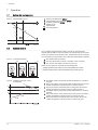
Control panel description
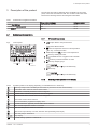
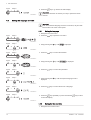
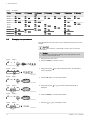
3.1.1 What each key means
1
h
Escape: Back to the previous level.
Reset: Manual reset.
2
CH flow temperature Access to set temperature.
Min. key: Lowering the value.
3
DHW temperature: Access to set temperature.
Plus key: Raising the value.
4
CH/DHW function: Toggles function ON/OFF
Enter key: Confirms selection or value.
5
Chimney-sweeping keys
Important
Press the 1 and 2 keys simultaneously.
6
Menu keys
Important
Press the 3 and 4 keys simultaneously.
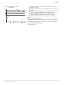
3.1.2
Meaning of the symbols on the display
Tab.2 Possible symbols in the display (depending on available devices or functions)
Chimney sweep mode is enabled (forced full load or part load for
O
2
/CO
2
measurement).
Information menu: read out various current values.
User menu: user-level parameters can be configured.
Installer menu: installer level parameter can be configured.
Manual mode menu: manual mode can be configured.
Error menu: errors can be read out.
Hour counter/timer program/time display menu.
Control PCB menu: (optional) control PCBs can be read out.
The outside temperature sensor is connected.
The room temperature sensor is connected.
The burner output level (1 to 5 bars, with each bar representing 20% output)
The heat pump is switched on.
-
Day display
Central heating operation is switched off.
Fig.1 Control panel
AD-3000833-01
1 2 3 4
5 6
3 Description of the product
7699084 - v.02 - 16102018 7

DHW operation is switched off.
The solar boiler is on and its heat level is displayed.
System water pressure display.
The holiday program is enabled.
Frost protection operation is enabled.
CH operation is enabled.
DHW operation is enabled.
Displaying the selected PCB.
The three-way valve is switched on.
The circulation pump is turning.
ECO mode operation is enabled.
Switch the appliance off then on again.
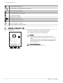
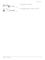
3.2
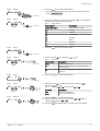
Description of the SCB-01 PCB
The expansion board SCB-01 has the following features:
0–10 V output connection for a PWM system pump
Two potential-free contacts for status notification
Important
If the boiler is fitted with the SCB-01 board, then this is
automatically recognised by the automatic control unit of the
boiler.
On removing this board, the boiler will show an error code. To
prevent this error, carry out an auto-detect immediately after
removing this board.
For more information, see
Carrying out an auto-detect, page 18
Fig.2 SCB-01 PCB
AD-0000660-01
Status
Nc
C No
Status
Nc
C No
+
0
0 -10
SCB-01
3 Description of the product
8 7699084 - v.02 - 16102018

4 User instructions
4.1 Use of the control panel
4.1.1 Browsing in the menus
Important
Depending on the devices or control PCBs connected, the
control panel shows selection options in some menus.
First, select a device, control PCB or zone to view or amend a
setting.
1. Press any key to activate the controller from the stand-by screen.
2. Access the available menu options by pressing the two keys on the
right simultaneously.
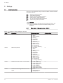
Tab.3 Possible menu choices
Information Menu
User menu
Installer Menu
Manual mode menu
Failure Menu
Hour Run Meters / Timer Program / Clock menu
PCB menu
(1)
(1) The icon is displayed only if an optional control PCB has been instal
led.
3. Press the key to move the cursor to the right.
4. Press the key to move the cursor to the left.
5. Press the key to confirm selection of the required menu or
parameter.
6. Press the or key to modify the value.
7. Press the key to confirm the value.
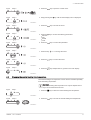
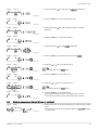
Fig.3
Step 1
MW-3000377-02
Fig.4 Step 2
MW-3000299-01
Fig.5 Step 3
MW-3000300-02
Fig.6 Step 4
MW-3000301-02
Fig.7 Step 5
MW-3000302-01
Fig.8 Step 6
MW-3000303-01
Fig.9 Step 7
MW-3000304-01
4 User instructions
7699084 - v.02 - 16102018 9

8. Press the
h
key to go back to the main display.
Important
The screen will return to stand-by if no key is pressed for three
minutes.
4.2 Setting the language and time
Important
First set the desired language, then the correct time, day and date
before further use of the control panel.
4.2.1 Setting the language
1. Navigate to the User menu.
2. Press the key to open the User menu.
3. Keep pressing the key until is displayed.
4. Press the key to confirm the selection.
5. Keep pressing the key until is displayed.
6. Press the key to confirm the parameter.
7. Keep pressing the key until the required language code is
displayed.
8. Press the key to confirm the choice of language.
9. Press the
h
key repeatedly or press and hold the
h
key to return
to the main display.
4.2.2 Setting the time and date
1. Navigate to the Counter menu.
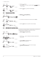
Fig.10
Step 8
MW-3000305-01
Fig.11 Step 2
MW-3000309-01
Fig.12 Step 3
MW-3000390-01
Fig.13 Step 4
MW-3000333-01
Fig.14 Step 5
MW-3000348-01
Fig.15 Step 6
MW-3000349-01
Fig.16 Step 7
MW-3000419-03
Fig.17 Step 8
MW-3000447-03
Fig.18 Step 9
MW-3000311-01
4 User instructions
10 7699084 - v.02 - 16102018

2. Press the key to open the counter menu.
3. Keep pressing the key until the Time display menu is displayed.
4.
Press the key to access the hours.
5. Press the key to access the following parameters:
Minutes
Day
Month
Year
6. Press the key to confirm the parameter.
7. Press the key or to change the value.
8. Press the key to confirm the value.
9. Press the
h
key multiple times to go back to the main display.
4.3
Changing the central heating flow temperature
The central heating flow temperature can be raised or lowered separately
from the heating requirement.
Important
The central heating flow temperature can only be adjusted in this
way if an on/off thermostat is used.
1. Press the key to select the central heating flow temperature.
2. Press the key to access the central heating flow temperature.
Fig.19
Step 2
MW-3000320-01
Fig.20 Step 3
MW-3000393-01
Fig.21 Step 4
MW-3000353-01
Fig.22 Step 5
MW-3000446-01
Fig.23 Step 6
MW-3000354-01
Fig.24 Step 7
MW-3000355-01
Fig.25 Step 8
MW-3000354-01
Fig.26 Step 9
MW-3000397-01
Fig.27 Step 1
MW-3000366-01
Fig.28 Step 2
MW-3000367-01
4 User instructions
7699084 - v.02 - 16102018 11

3. Press the or key for the required CH flow temperature.
4. Press the key to confirm the value.
5. Press the
h
key to go back to the main display.
Important
The flow temperature is matched automatically when using a:
weather-dependent regulator
OpenTherm regulator
eTwist modulating thermostat
4.4
Changing the DHW temperature
The temperature of the domestic hot water can be changed as needed.
1. Press the key to select the domestic hot water temperature.
2. Press the or key for the required DHW temperature.
3. Press the key to confirm the value.
4.5
Setting the Timer Program
If a timed thermostat is not being used, the timer program for the
appliance can be used. The Timer Program can be used to lower the
heating temperature during the night or an absence during the day. A start
and end time for the lower temperature can be set in the Timer Program.
Important
Activate the timer program using the parameter:
The timer program can be set for each zone (heating, domestic
hot water or cooling).
1. Navigate to the Counter menu.
2. Press the key to open the menu.
3. Keep pressing the key until the required zone is displayed.
If there is only a direct heating group, the only option that appears is
CIRCA (circuit A).
Fig.29
Step 3
MW-3000368-01
Fig.30 Step 4
MW-3000369-01
Fig.31 Step 5
MW-3000370-01
Fig.32 Step 1
MW-3000371-01
Fig.33 Step 2
MW-3000368-01
Fig.34 Step 3
MW-3000369-01
Fig.35 Step 2
MW-3000320-01
Fig.36 Step 3
MW-3000404-01
4 User instructions
12 7699084 - v.02 - 16102018

4. Press the key to confirm the selection.
The icons dedicated to the days of the week all flash at the same
time: .
5. Select the required day number by keeping the or key pressed
until the icon for the required day flashes.
Tab.4 Day numbers
Day selected Description
Every day of the week
Monday
Tuesday
Wednesday
Thursday
Friday
Saturday
Sunday
6. Press the key to confirm the selection.
7. Set the start time S1 by pressing the or key.
Tab.5 Options
Abbreviation Description
END End of programming
S Switching time or end of day indication (max. 6
switching times)
C Temperature setting (lower night or comfort tem
perature)
8. Press the key to confirm the selection.
9. Select the status C1 corresponding with the switch time S1 by
pressing the or key.
Tab.6 Statuses C1 to C6 for the periods S1 to S6
C1 to C6 Description
ON Comfort temperature
ECO Lower night temperature
10. Press the key to confirm the selection.
11. Repeat the steps to define the switch times (S1 to S6) and the
corresponding statuses (C1 to C6).
12. Press the
h
key multiple times to go back to the main display.
Fig.37
Step 4
MW-3000405-01
Fig.38 Step 5
MW-3000360-01
Fig.39 Step 6
MW-3000433-01
Fig.40 Step 7
MW-3000361-01
Fig.41 Step 8
MW-3000434-01
Fig.42 Step 9
MW-3000391-01
Fig.43 Step 10
MW-3000394-01
4 User instructions
7699084 - v.02 - 16102018 13

Tab.7 Example
Times
Monday
Tuesday
Wednes
day
Thursday
Friday
Saturday Sunday
06:00 S1
C1 = ON
S1
C1 = ON
S1
C1 = ON
S1
C1 = ON
S1
C1 = ECO
S1
C1 = ECO
S1
C1 = ON
08:00
10:00 S2
C2 = ECO
S2
C2 = ECO
S2
C2 = ECO
S2
C2 = ON
12:00 S2
C2 = ECO
14:00 S3
C3 = ON
S3
C3 = ON
S2
C2 = ECO
S3
C3 = ECO
16:00 S2
C2 = ON
18:00 S3
C3 = ON
S4
C4 = ECO
S3
C3 = ON
S4
C4 = ON
20:00 S4
C4 = ECO
22:00 S4
C4 = ECO
S4
C4 = ECO
S5
C5 = ECO
23:50
4.6
Changing user parameters
The parameters in the user menu can be changed by the end user or the
installer.
Important
First, select a device, control PCB or zone to view or amend a
setting.
Caution
Modification of the factory settings may impair operation of the
device, control PCB or zone.
1. Navigate to the User menu.
2. Press the key to open the menu.
3. Keep pressing the key until the required device, control PCB or
zone is displayed.
4. Press the key to confirm the selection.
5. Keep pressing the or key until the required parameter is
displayed.
6. Press the key to confirm the selection.
7. Press the or key to modify the value.
Fig.44
Step 2
MW-3000309-01
Fig.45 Step 3
MW-3000402-02
Fig.46 Step 4
MW-3000333-01
Fig.47 Step 5
MW-3000310-01
Fig.48 Step 6
MW-3000333-01
Fig.49 Step 7
MW-3000334-01
4 User instructions
14 7699084 - v.02 - 16102018

8. Press the key to confirm the value.
9. Press the
h
key multiple times to go back to the main display.
Fig.50 Step 8
MW-3000335-01
Fig.51 Step 9
MW-3000311-01
4 User instructions
7699084 - v.02 - 16102018 15

5 Installer instructions
5.1 Changing installer parameters
The parameters in the Installer Menu must only be changed by a qualified
professional. Code
must be entered in order to change the
parameters.
Important
First, select a device, control PCB or zone to view or amend a
setting.
Caution
Modification of the factory settings may impair operation of the
device, control PCB or zone.
1. Navigate to the Installer menu.
2. Press the key to open the menu.
3. Keep pressing the key until the code is displayed.
4. Press the key to confirm opening the menu.
5. Keep pressing the key until the required device, control PCB or
zone is displayed.
6. Press the key to confirm the selection.
7. Keep pressing the or key until the required parameter is
displayed.
8. Press the key to confirm the selection.
9. Press the or key to modify the value.
10. Press the key to confirm the value.
Fig.52
Step 2
MW-3000312-01
Fig.53 Step 3
MW-3000313-01
Fig.54 Step 4
MW-3000314-01
Fig.55 Step 5
MW-3000406-02
Fig.56 Step 6
MW-3000407-01
Fig.57 Step 7
MW-3000315-01
Fig.58 Step 8
MW-3000336-01
Fig.59 Step 9
MW-3000337-01
Fig.60 Step 10
MW-3000338-01
5 Installer instructions
16 7699084 - v.02 - 16102018

11. Press the
h
key multiple times to go back to the main display.
5.2
Adjusting advanced parameters
The advanced parameters at installer level may only be changed by a
qualified professional. Code must be entered in order to change
the parameters.
Important
First, select a device, control PCB or zone to view or amend a
setting.
Caution
Modification of the factory settings may impair operation of the
device, control PCB or zone.
1. Navigate to the Installer menu.
2. Press the key to open the menu.
3. Keep pressing the key until the code is displayed.
4. Press the key to confirm opening the menu.
5. Keep pressing the key until the required device, control PCB or
zone is displayed.
6. Press the key to confirm the selection.
7. Keep pressing the key until is displayed.
Important
The text can only appear if the advanced parameters for
the appliance, control PCB or zone are available.
8. Press the key to confirm the selection.
9. Press the or key to modify the value.
Fig.61
Step 11
MW-3000316-01
Fig.62 Step 2
MW-3000312-01
Fig.63 Step 3
MW-3000313-01
Fig.64 Step 4
MW-3000314-01
Fig.65 Step 5
MW-3000406-02
Fig.66 Step 6
MW-3000407-01
Fig.67 Step 7
MW-3000408-01
Fig.68 Step 8
MW-3000407-01
Fig.69 Step 9
MW-3000337-01
5 Installer instructions
7699084 - v.02 - 16102018 17

10. Press the key to confirm the value.
11. Press the
h
key multiple times to go back to the main display.
5.3
Carrying out an auto-detect
Carry out an auto-detect after removing or replacing an (optional) control
PCB.
1. Navigate to the Installer menu.
2. Press the key to open the menu.
3. Keep pressing the key until the code is displayed.
4. Press the key to confirm opening the menu.
5. Keep pressing the key until the device is displayed.
6. Press the key to confirm the selection.
7. Keep pressing the key until is displayed.
8. Press the key to carry out the auto-detect.
9. After a while, the main display is shown; auto-detect is complete.
5.4
Restoring to factory settings
1. Navigate to the Installer menu.
2. Press the key to open the menu.
Fig.70
Step 10
MW-3000338-01
Fig.71 Step 11
MW-3000316-01
Fig.72 Step 2
MW-3000312-01
Fig.73 Step 3
MW-3000313-01
Fig.74 Step 4
MW-3000314-01
Fig.75 Step 5
MW-3000406-02
Fig.76 Step 6
MW-3000407-01
Fig.77 Step 7
MW-3000412-01
Fig.78 Step 8
MW-3000413-01
Fig.79 Step 2
MW-3000312-01
5 Installer instructions
18 7699084 - v.02 - 16102018

3. Keep pressing the key until the code is displayed.
4. Press the key to confirm opening the menu.
5.
Keep pressing the key until the required device or PCB is
displayed.
6. Press the key to confirm the selection.
7. Keep pressing the key until is displayed.
8. Press the key to open the first factory setting .
9. Press the or keys to modify the value.
See
The data plate for the value.
10. Press the key to confirm the value.
11. Press the or keys to modify the value.
See
The data plate for the value.
12. Press the key to confirm the value.
The factory settings are reset. The display shows various
information and returns to the main display after 3 minutes.
5.5
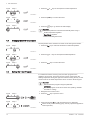
Chimney sweep mode (forced full load or part load)
1. Press the two keys on the left simultaneously to select chimney sweep
mode.
The device is now running at part load. Wait until appears
on the display.
Fig.80
Step 3
MW-3000313-01
Fig.81 Step 4
MW-3000314-01
Fig.82 Step 5
MW-3000406-02
Fig.83 Step 6
MW-3000407-01
Fig.84 Step 7
MW-3000448-01
Fig.85 Step 6
MW-3000343-01
Fig.86 Step 7
MW-3000344-01
Fig.87 Step 8
MW-3000345-01
Fig.88 Step 9
MW-3000346-01
Fig.89 Step 10
MW-3000347-01
Fig.90 Step 1
MW-3000325-01
5 Installer instructions
7699084 - v.02 - 16102018 19

2. Press the key twice.
The device is now running at full load. Wait until appears
on the display.
3. Press the
h
key to go back to the main display.
5.6
Connected control PCBs
1. Navigate to the control PCB menu.
2. Press the key to open the menu.
3. To see which control PCBs are connected, press the key.
4. Press the
h
key twice to go back to the main display.
5.7 Activating the manual mode menu
In some cases, it may be necessary to set the device to manual mode, for
example when the controller has not yet been connected.
1. Navigate to the manual mode menu.
2. Press the key to open the menu.
3. Press the or keys to modify the required flow temperature in
manual mode.
4. Press the key to confirm the value.
Manual mode is switched on.
5. Press the
h
key twice to go back to the main display.
Manual mode is switched off.
Fig.91
Step 2
MW-3000326-01
Fig.92 Step 3
MW-3000327-01
Fig.93 Step 2
MW-3000339-01
Fig.94 Step 3
MW-3000340-01
Fig.95 Step 4
MW-3000341-01
Fig.96 Step 2
MW-3000302-01
Fig.97 Step 3
MW-3000303-01
Fig.98 Step 4
MW-3000304-01
Fig.99 Step 5
MW-3000305-01
5 Installer instructions
20 7699084 - v.02 - 16102018
Page is loading ...
Page is loading ...
Page is loading ...
Page is loading ...
Page is loading ...
Page is loading ...
Page is loading ...
Page is loading ...
Page is loading ...
Page is loading ...
Page is loading ...
Page is loading ...
-
 1
1
-
 2
2
-
 3
3
-
 4
4
-
 5
5
-
 6
6
-
 7
7
-
 8
8
-
 9
9
-
 10
10
-
 11
11
-
 12
12
-
 13
13
-
 14
14
-
 15
15
-
 16
16
-
 17
17
-
 18
18
-
 19
19
-
 20
20
-
 21
21
-
 22
22
-
 23
23
-
 24
24
-
 25
25
-
 26
26
-
 27
27
-
 28
28
-
 29
29
-
 30
30
-
 31
31
-
 32
32


Ask a question and I''ll find the answer in the document
Finding information in a document is now easier with AI
Related papers
-
REMEHA Gas 320/620 Ace User manual
-
REMEHA Quinta Ace User manual
-
-
-
-
-
-
-
-
Other documents
-
VOKERA evolve 24C Operating instructions
-
-
 De Dietrich NeOvo EcoNox - EF 36 / EF 46 User manual
-
 De Dietrich EFU C 40 / EFU C 50 User manual
-
 De Dietrich NeOvo EcoNox - EFU 36 / EFU 46 User manual
-
 De Dietrich Installation and User Manual High-efficiency wall-hung gas boiler - AMC Pro 45 - 65 - 90 - 115 - Diematic Evolution User manual
-
De Dietrich EcoNox EFU 36 User manual
-
 De Dietrich EFU-S 22/29 User manual
-
 De Dietrich EFU C-S 19/24/32 User manual
-
 De Dietrich EFU C 19/24/32 User guide


