Lithonia Lighting OMS 1000 120 DDB M6 Installation guide

Type
Installation guide
page 1
Protect yourself. Before installing, read the entire
instructions carefully and save them for future
reference. Date installed:_____________
INSTALLATION INSTRUCTIONS
UOMS1000_Rev 1/14
Specications MODEL # OMS 1000
Power Requirements:.......120VAC, 60 Hz
Switching Capacity: .........8 A, Resistive
1.25A General Purpose (LED Driver)
500 watts Incandescent
250 watts Fluorescent
150 watts Ballast
Sensing Angle: .................Up to 180°
Range: ............................Up to *70 feet (21m)
*varies with surrounding temperature
Time Adjustment: ....................1, 5 or 10 min
Power Consumption:.........<1 watt
Surge protection:............... up to 6kV
UL Listing: .........................Wet location
Requirements
• The light control requires 120 volts AC
• To comply with California Energy Commission, it is required that the
control is wired through a switch.
• If you want to use the Manual Override mode, the control must
be wired through a switch. Note: Do not use with light dimmer or
timecontroled circuits.
• This product is intended for use with a junction box marked for use in
wet locations.
• Do not install on the same circuit with an electic motor.
• For best performance, mount 6-10ft high.
Motion Sensor
HOW DOES THE MOTION SENSOR WORK?
The Motion Sensor’s infrared sensor “sees” small temperature
changes caused by the motion of objects within its detection zone
and turns on the lights automatically. Large animals or a strong
infraredsourcesuchasvehicleheadlightsorsunlightreectingoff
a surface can also trigger the sensor.
HOW LONG DO THE LIGHTS STAY ON?
Lights remain on as long as there is movement within the detection
zone. Once the zone is vacated, lights can be adjusted to remain
on for approximately 1 to 10 minutes.
WHAT IS THE SIZE OF THE DETECTION ZONE?
Sensors can detect motion up to 70’ away in a 180° detection range.
As the distance from the sensor increases, larger movement will be
required for detection. For example at 10’ a single step across the
detection pattern may be enough to trigger the light, while at 50’
several steps may be necessary for detection.
Sensors function best when the direction of expected movement is
across its detection pattern, not towards the sensor. Mount 6-10 ft
high for optimum range and detection.
Model Number: OMS 1000
CAN THE LIGHTS STILL BE TURNED ON/OFF
WITH A LIGHT SWITCH?
At night lights can be turned on or off manually with a wall switch
or circuit breaker.
page 2
•Toreducetheriskofdeath,personalinjuryorpropertydamagefromre,
electric shock, falling parts, cuts/abrasions, and other hazards please
readallwarningsandinstructionsincludedwithandonthexturebox
andallxturelabels.
• Beforeinstalling,servicing,orperformingroutinemaintenanceuponthis
equipment, follow these general precautions.
• Commercialinstallation,serviceandmaintenanceofluminairesshould
beperformedbyaqualiedlicensedelectrician.
• ForResidentialinstallation:Ifyouareunsureabouttheinstallationor
maintenanceoftheluminaires,consulta qualied licensed electrician
and check your local electical code.
• Maintenance of the luminaires should be performed by person(s)
familiar with the luminaires’ construction and operation and any hazards
involved.Regularxturemaintenanceprogramsarerecommended.
• This xture is intended to be connected to a properly installed and
grounded UL listed junction box.
• Itwill occasionally be necessaryto clean the outsideof the refractor/
lens. Refractor/lens should be washed in a solution of warm water and
any mild, non-abrasive household detergent, rinsed with clean water and
wiped dry. Should optical assembly become dirty on the inside, wipe
refractor/lens and clean in above manner, replacing damaged gaskets
as necessary.
• DO NOT INSTALL DAMAGED PRODUCT! This luminaire has been
properly packed so that no parts should have been damaged during
transit.Inspecttoconrm.Anypartdamagedorbrokenduringorafter
assembly should be replaced.
• Recycle: For information on how to recycle LED electronic products,
please visit www.epa.gov.
• These instructions do not purport to cover all details or variations
in equipment nor to provide every possible contingency to meet in
connection with installation, operation, or maintenance. Should further
information be desired or should particular problems arise which are not
coveredsufcientlyforthepurchaser’sorowner’spurposes,thismatter
should be referred to Acuity Brands Lighting, Inc.
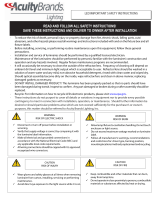
IMPORTANT SAFETY INSTRUCTIONS
READ AND FOLLOW THESE SAFETY INSTRUCTIONS!
WARNING
RISK OF ELECTRIC SHOCK
CAUTION
RISK OF INJURY
CAUTION
RISK OF FIRE
CAUTION
RISK OF PRODUCT DAMAGE
WARNING
RISK OF BURN
Disconnect or turn off power before installation or servicing.
Verify that supply voltage is correct by comparing it with the luminaire
label information.
Make all electrical and grounded connections in accordance with
the National Electrical Code (NEC) and any applicable local code
requirements.
All wiring connections should be capped with UL approved wire
connectors.
Wear gloves and safety glasses at all times when removing luminaire
from carton, installing, servicing or performing maintenance.
Avoid direct eye exposure to the light source while it is on.
Keep combustible and other materials that can burn, away from lamp/
lens.
Do not operate in close proximity to persons, combustible materials or
substances affected by heat.
Never connect components under load.
Donotmountorsupportthesexturesinamannerthatcancuttheouter
jacket or damage wire insulation.
Unlessindividualproductspecicationsdeemotherwise:Neverconnect
an LED product directly to a dimmer packs, occupancy sensor, timing
device,orotherrelatedcontroldevices.LEDxturesmustbepowered
directly off a switched circuit.
Unlessindividualproductspecicationsdeemotherwise:Donotrestrict
xtureventilation.Allowforsomevolumeofairspacearoundthexture.
AvoidcoveringLEDxtureswithinsulation,foam,orothermaterialthat
will prevent convection or cooling.
Unlessindividualproductspecicationsdeemotherwise:Donotexceed
xturesmaximumambienttemperature.
Onlyusextureinitsintendedlocation.
LED products are Polarity Sensitive. Ensure proper Polarity before
installation.
ElectrostaticDischarge(ESD):ESDcandamageLEDxtures.Personal
grounding equipment must be worn during all installation or servicing
of unit.
Do not touch individual electrical components as this can cause ESD,
shorten lamp life, or alter performance.
Some components inside the xture may not be serviceable. In the
unlikely event your unit may require service, stop using the unit
immediately and contact an ABL representative for assistance.
Changes or modications not expressly approved by Acuity Brands
Lighting could void the authority to operate the equipment.
Always read the xtures complete installation instructions prior to
installationforanyadditionalxturespecicwarnings.
Allowlamp/xturetocoolbeforehandling.Donottouchenclosure,lens
or light source.
Do not exceed maximum wattage marked on luminaire label.
Follow all manufacturer’s warnings, recommendations and restrictions
including but not limited to: driver type, burning position, mounting
locations/methods, replacement and recycling.
Use only lamps that comply with ANSI standards.
5-YEAR LIMITED WARRANTY
Register your warranty on www.lightahome.com/warranty. Your prompt
productregistrationconrmsyourrighttotheprotectionavailableunder
the terms and conditions of your Lithonia Lighting warranty.
Failure to follow any of these instructions could void product warranties.
For a complete listing of product Terms and Conditions, please visit www.
acuitybrands.com. Acuity Brands Lighting, Inc. assumes no responsibilities
for claims arising out of improper or careless installation or handling of its
products.
page 3
INSTALLATION INSTRUCTIONS
1. Remove all components and parts pack from packaging.
Check to ensure all parts are included. Note: Account for small
parts and destroy packing material, as these may be hazardous to
children.
Turn OFF Power at circuit breaker box.
CAUTION: Do not rely on wall switch alone to turn off power.
Note: Motion sensor can be mounted to an eave or wall mount UL
listed junction box.
2. Thread the motion sensor into UL Listed mounting plate or
junction box with a 1/2” NPT threaded plug. Mounting plate sold
separately.
Multiplexturesmaybewiredtoasinglesensor.Tohandleloads
greaterthanthewattageslistedinspecs,aqualiedelectrician
should install a relay.
WIRING THE MOTION SENSOR
Make sure power is turned off.
3. Use included UL listed connector to connect the (copper) house
supply ground wire & the (green) mounting plate ground wire.
Note: If house wiring does not include a ground wire, consult your
local electrical code for approved grounding methods.
For proper connection, place wire nut over
wires and twist clockwise until tight.
4. Use included UL listed connector to connect the black lamp
head wires to the red motion sensor wires.
5. Use included UL listed connector to connect the white
lamphead & white senor wires to the white power supply wire then
connect the black sensor wire to the black supply wire.
6. Install mounting plate to junction box.
Note: Lamp heads must be positioned above motion sensor head
and controls on motion sensor must face the ground.
7. Turn on electricity at fuse or circuit breaker box and verify
success of installation.
8. Apply silicone caulking (not included) around the perimeter
of the mounting plate and junction box where it contacts the
mounting surface for moisture seal.
See next pages for MOTION SENSOR SET UP INSTRUCTIONS
BASIC WIRING DIAGRAM
BASIC WIRING WITH BACKPLATE
MULTIPLE FIXTURE WIRING
page 4
SETTING THE MOTION SENSOR
After installing your motion-activated light you are ready to set/aim
the motion sensor. Make sure the wall switch is in the ON position.
Do NOT use with dimmers or timers or on multiple switch circuits.
Do NOT install on the same circuit with an electric motor (i.e.
appliances, HVAC equipment, washer/dryer garage door
openers, etc.)
1. Slide the TIME/TEST switch in TEST position to disable the
photo eye and allow light to come on during daylight hours for a
short time.
2. Turn the SENSITIVITY knob approximately 2/3 clockwise
and increase if necessary.
3. Aim the MOTION SENSOR HEAD level and at least 10°
downward andacrossthetrafcpatternyouwanttodetect.
CAUTION - RISK OF SHOCK
AIM MOTION DETECTOR 10° BELOW HORIZONTAL. MAKE
SURE CONTROL KNOBS AND SWITCHES FACE TOWARDS
THE GROUND. WATER MAY ACCUMULATE INSIDE MOTION
DETECTOR IF NOT POSITIONED PROPERLY.
CAUTION: Part of the far region looks above the hood line, so
do not aim the head too high. Aiming the head to high can lead to
false activations.
Note: Ifxtureismountedhigherthan10ft(3m),thedistance
and downward sensitivity will be reduced. The detector is less
sensitive to motion directly towards it.
Avoid aiming the control at:
• Objects that change temperature rapidly, such as heating
vents and air conditioners. These heat sources could cause
false triggering.
• Areas where pets or trafc may trigger the control.
Nearby large, light-colored objects reecting light may
trigger the shut-off feature. Do not point other lights at the sensor.
4. Test motion detection zone by walking across the pattern
in the targeted coverage area. A red LED indicator light in the
motionheadwillashwhenmotionisdetectedandthelights
will come on for approximately 4 seconds. Note: The red LED
indicator light is a visual indicator that the motion detector is
sensing motion.
Move to a different spot in the area to be tested and stop all
motion for approximately 8 seconds. The lights should turn off.
Start walking again to see if your motion is detected in the new
spot.
Repeat the walk test in other spots to determine the coverage
area.Yourmotionsensorlooksformotionin3differentregionsas
pictured in Fig. C, the far, mid, and near region. Be sure to walk
through the entire area to test the coverage in all regions.
As distance from the sensor increases, it will take more movement
to be detected. The sensitivity can be adjusted to increase or
decrease detection if desired. Adjust the sensitivity as needed.
Sensitivity set too high may cause false triggering.
Photo eye TIME/TEST switch
Figure C
WRONG
OK
Sensor
Least Sensitive Most Sensitive
Motion
Motion
page 5
Photo eye TIME/TEST switch
SETTING THE MOTION SENSOR
Note: Walk in a zigzag direction. Walking up to the motion
detector in a straight line may keep you in between detection
regions, and your light will not come on.
MOTION DETECTOR SET UP NOTES
If the lights stay on all the time: the sensitivity may be too high
or the motion detector head might be aimed too high. Try turning
the sensitivity down, and try aiming the head slightly lower. See
trouble shooting guide.
5. SET ON TIME
Whenyouaresatisedwiththeareaofcoverage,slidetheTIME/
TEST switch towards the opposite end. Sliding the switch back
will let you adjust the time the light will stay on after motion is
detected in increments of 1, 5 or 10 minutes. (Note: now light will
onlycomeonatnight!)
MANUAL OVERRIDE
To disable the motion sensor and keep the light continuously on
forthenight,ipthewallswitchofffor2secondsandthenback
on.
ToresettoSecuritymode,iptheswitchoffagainfor2seconds
and then back on.
If you leave the light on all night it will automatically turn off at
dawn and reset to Security mode.
NOTE: If you get confused while switching modes, turn the power
at the breaker or wall switch off for one minute, then back on. After
the calibration time, the control will be in the Security mode.
IMPORTANT SEASONAL CHANGES:
The motion sensor works by sensing temperature changes across
itseldofview.Thecloserthesurroundingtemperatureistoa
person’s temperature the less sensitive the sensor will appear.
The greater the temperature difference, the more sensitive the
sensor will appear. The range may need to be readjusted with the
sensitivity dial as temperature changes for different seasons. This
is a normal part of the light sensor’s operation.
2 Seconds OFF then...
...back on
Acuity Brands Lighting, Inc.
One Lithonia Way, Conyers, GA 30012
www.AcuityBrands.com
SYMPTOM POSSIBLE CAUSE SOLUTION
Lights will not come on 1. Light switch is turned off.
2. Fuse is blown or circuit breaker is turned off.
3. Incorrect circuit wiring.
4. Outdoor temperature is getting warmer.
5. Photocontrol does not work.
6. Motion is not detected.
1. Turn light switch on.
2. Replace fuse or turn circuit breaker on.
3. Verify wiring is correct.
4. Increase sensitivity.
5. Slide the TIME/TEST switch in Test position to
test if photocontrol works properly.
6. Check if red LED indicator light comes on.
Lights come on in daylight 1. Sensor may be located in a relatively dark
location.
2. Sensor is in TEST mode.
1. Fixture is operating normally under these
conditions.
2. Slide TIME/TEST switch in Time position.
Lights come on for no
apparent reason.
1. Sensor maybe detecting small animals or
cars.
2. Sensitivity set too high.
3. The outdoor temperature is getting cooler.
Reduce sensitivity (see seasonal changes).
Lights stay on continuously 1. Sensor is in Manual Override mode.
2. Coverage area may be too large.
3. The sensor may be picking up a heat
source like an air vent, dryer vent, or brightly
painted,heat-reectivesurface.
1. Follow manual override instructions to reset.
2. Adjust the motion sensor downward.
3. Reduce sensitivity.
Lightsashonandoff
(strobing)
1. Heat or light from the lamps may be turning
the light control on and off.
2. Heatbeingreectedfromotherobjectsmay
be affecting the sensor.
3. Sensor is in Test mode.
4. Lightscontrolledbysensorshineorreect
into the photocell.
1. Reposition the lamp heads away from the
sensor.
2. Reduce sensitivity.
3. While in TEST mode, light only stays on for 5
seconds.
4. Reposition sensor in small increments.
Range appears limited 1. Sensor is not level.
2. Sensor is mounted too high.
3. Movement is directly towards sensor.
1. Position sensor exactly level from side to side
2. If mounted above 20 feet, much of the usable
range will be lost. Mount at 6 to 10 feet for max.
range.
3. Adjust Sensor. Sensor will see movement
across detection pattern more quickly. Adjust
sensor in ¼” increments.
Lights will not trigger with
motion
1. Sensitivity may be set too low.
2. Motion Head not aimed correctly.
3. No motion is detected.
1. Turn up sensitivity in small steps
2. See section for aiming and setting motion
sensor.
3. VerifyredLEDindicatorlightisashing
If further technical assistance is required, contact: Technical Support at: (800) 279-8041
Clean surfaces with mild soap and water. Do not use abrasive materials such as scouring pads or powders, steel wool or
abrasive paper.
WARNING: There are no user serviceable parts inside this motion sensor.
Ifthisxturefailstooperateproperly,usetheguidebelowtodiagnoseandcorrecttheproblem.
TROUBLE SHOOTING GUIDE
UOMS1000_Rev 1/14
  • Page 1 1
  • Page 2 2
  • Page 3 3
  • Page 4 4
  • Page 5 5
  • Page 6 6
  • Page 7 7
  • Page 8 8
  • Page 9 9
  • Page 10 10
  • Page 11 11
  • Page 12 12
  • Page 13 13
  • Page 14 14
  • Page 15 15
  • Page 16 16
  • Page 17 17
  • Page 18 18

Lithonia Lighting OMS 1000 120 DDB M6 Installation guide

Type
Installation guide

Ask a question and I''ll find the answer in the document

Finding information in a document is now easier with AI