
vacon
®
20 cp
ac drives
Installation, Technical and Maintenance
Manual


vacon • 3
Local contacts: http://drives.danfoss.com/danfoss-drives/local-contacts/
INDEX
Document code (Original Instructions): DPD00489K
Order code: DOC-INS03976+DLUK
Rev. K
Revision release date: 29.8.18
1. Safety................................................................................................................6
1.1 Signs....................................................................................................................................6
1.2 Units ....................................................................................................................................6
1.3 Danger.................................................................................................................................7
1.4 Hot surface warning............................................................................................................7
1.5 Warnings .............................................................................................................................8
1.6 Grounding and earth fault protection.................................................................................9
1.7 Insulation system..............................................................................................................10
1.8 Compatibility with RCDs ...................................................................................................12
1.9 Cooling System .................................................................................................................13
2. Receipt of delivery ..........................................................................................14
2.1 Type designation code.......................................................................................................15
2.2 Order codes.......................................................................................................................16
2.3 Unpacking and lifting the AC drive ...................................................................................16
2.4 Accessories .......................................................................................................................17
2.4.1 Disposal.............................................................................................................................17
3. Mounting.........................................................................................................18
3.1 Dimensions .......................................................................................................................18
3.1.1 Enclosure MS2 three-phase version ................................................................................18
3.1.2 Enclosure MS2 single-phase version...............................................................................19
3.1.3 Enclosure MS3 ..................................................................................................................20
3.2 Cooling ..............................................................................................................................21
3.3 Environment temperature ................................................................................................21
3.4 Heatsink assembly instructions .......................................................................................21
3.5 Installation spacing...........................................................................................................24
3.6 Power loss thermal characteristics .................................................................................25
3.7 Dimensioning an external heatsink..................................................................................26
4. Power cabling .................................................................................................29
4.1 Circuit breaker ..................................................................................................................31
4.2 UL standards on cabling...................................................................................................31
4.3 Description of the terminals .............................................................................................32
4.3.1 MS2 three-phase version power connections..................................................................32
4.3.2 MS2 single-phase version power connections.................................................................33
4.3.3 MS3 power connections....................................................................................................34
4.4 Cable dimensioning and selection....................................................................................35
4.4.1 Cable and fuse sizes, enclosures MS2 to MS3.................................................................35
4.4.2 Cable and fuse sizes, enclosures MS2 to MS3, North America.......................................36
4.5 Brake resistor cables........................................................................................................37
4.6 Control cables ...................................................................................................................37
4.7 Cable installation ..............................................................................................................37
5. Control unit.....................................................................................................39
5.1 Control unit cabling...........................................................................................................42
5.1.1 Control cable sizing ..........................................................................................................42
5.1.2 Standard I/O terminals .....................................................................................................43
5.1.3 Relay terminals .................................................................................................................44
5.1.4 Safe Torque off (STO) terminals .......................................................................................44
5.1.5 Description of additional echo connectors.......................................................................45
5.1.6 Led handling......................................................................................................................49

vacon • 4
Local contacts: http://drives.danfoss.com/danfoss-drives/local-contacts/
5.1.7 Selection of terminal functions with dip switches ...........................................................50
5.2 Fieldbus connection..........................................................................................................51
5.2.1 Modbus RTU protocol .......................................................................................................52
5.2.2 Preparation for use through RS485..................................................................................53
6. Commissioning ...............................................................................................54
6.1 Commissioning of the drive ..............................................................................................55
6.2 Changing EMC protection class........................................................................................56
6.2.1 Changing EMC protection class - MS2 three-phase version ...........................................56
6.2.2 Changing EMC protection class - MS2 single-phase version..........................................58
6.2.3 Changing EMC protection class - MS3 .............................................................................59
6.3 Running the motor ............................................................................................................60
6.3.1 Cable and motor insulation checks ..................................................................................60
6.4 Maintenance......................................................................................................................61
6.4.1 Recharging capacitors in stored units..............................................................................61
7. Technical data.................................................................................................62
7.1 AC drive power ratings......................................................................................................62
7.1.1 Mains voltage 3AC 208-240V.............................................................................................62
7.1.2 Mains voltage 1AC 208-240V.............................................................................................62
7.1.3 Mains voltage 3AC 380-480V.............................................................................................63
7.1.4 Definitions of overloadability ............................................................................................63
7.2 Brake resistors .................................................................................................................64
7.2.1 Internal brake resistor......................................................................................................64
7.2.2 External brake resistor.....................................................................................................64
7.3 VACON® 20 CP - technical data.......................................................................................65
7.3.1 Technical information on control connections.................................................................68
8. Options............................................................................................................70
8.1 VACON® keypad with seven-segment display.................................................................70
8.2 Text keypad .......................................................................................................................71
8.3 Menu structure .................................................................................................................72
8.4 Using the keypad...............................................................................................................73
8.4.1 Main menu.........................................................................................................................73
8.4.2 Resetting fault...................................................................................................................74
8.4.3 Local/Remote control button............................................................................................74
8.4.4 Reference menu................................................................................................................75
8.4.5 Monitoring menu...............................................................................................................76
8.4.6 Parameter menu...............................................................................................................77
8.4.7 System/Fault menu...........................................................................................................78
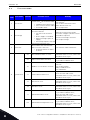
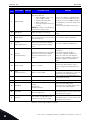
8.5 Fault tracing......................................................................................................................80
8.6 Option boards....................................................................................................................84
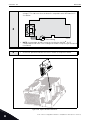
8.6.1 Option board installation ..................................................................................................85
9. Safe Torque Off ...............................................................................................88
9.1 General description...........................................................................................................88
9.2 Warnings ...........................................................................................................................89
9.3 Standards ..........................................................................................................................90
9.4 The principle of STO..........................................................................................................91
9.4.1 Technical details ...............................................................................................................92
9.5 Connections.......................................................................................................................93
9.5.1 Safety Capability Cat. 4 / PL e / SIL 3 ...............................................................................94
9.5.2 Safety Capability Cat. 3 / PL e / SIL 3 ...............................................................................96
9.5.3 Safety Capability Cat. 2 / PL d / SIL 2 ...............................................................................96
9.5.4 Safety Capability Cat. 1 / PL c / SIL 1................................................................................97
9.6 Commissioning .................................................................................................................98
9.6.1 General wiring instructions ..............................................................................................98
9.6.2 Checklist for commissioning ............................................................................................98

vacon • 5
Local contacts: http://drives.danfoss.com/danfoss-drives/local-contacts/
9.7 Parameters and fault tracing ...........................................................................................99
9.8 Maintenance and diagnostics ...........................................................................................99

1
vacon • 6 Safety
Local contacts: http://drives.danfoss.com/danfoss-drives/local-contacts/
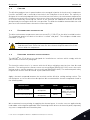
1. SAFETY
This manual contains clearly marked warning information which is intended for your personal
safety and to avoid any unintentional damage to the product or connected appliances.
Please read the warning information carefully.
VACON
®
CP is a Cold Plate drive designed to control asynchronous AC motors and permanent
magnet motors. The product is intended to be installed in a restricted access location and for a
general purpose use.
Only VACON
®
authorized, trained and qualified personnel are allowed to install, operate and
maintain the drive.
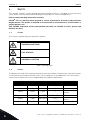
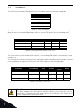
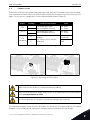
1.1 Signs
The cautions and warnings are marked as follows:
Table 1. Warning signs.
1.2 Units
The dimensions used in this manual conform to International Metric System units, otherwise known
as SI (Système International d’Unités) units. For the purpose of the equipment's UL certification,
some of these dimensions are accompanied by their imperial equivalents.
= DANGEROUS VOLTAGE!
= HOT SURFACE!
= WARNING or CAUTION
Physical
dimension
SI value US value Conversion factor US designation
length 1 mm 0.0394 inch 25.4 inch
Weight 1 kg 2.205 lb 0.4536 pound
Speed
1 min
-1
1 rpm 1
revolution per
minute
Temperature 1 °C (T1) 33.8 °F (T2) T2 = T1 x 9/5 + 32 Fahrenheit
Torque 1 Nm 8.851 lbf in 0.113
pound-force
inches
Power 1 kW 1.341 HP 0.7457 horsepower
Table 2. Unit conversion table.

Safety vacon • 7
Local contacts: http://drives.danfoss.com/danfoss-drives/local-contacts/
1
1.3 Danger
1.4 Hot surface warning
The components of the power unit of VACON
®
20 CP drives are live when the
drive is connected to mains potential. Coming into contact with this voltage is
extremely dangerous and may cause death or severe injury.
The motor terminals (U, V, W) are live when VACON
®
20 CP Drive is connected to
the mains, even if the motor is not running.
After disconnecting the AC drive from the mains, wait until the indicators on the
keypad go out (if no keypad is attached, see the indicators on the cover). Wait an
additional 30 seconds before starting any work on the connections of VACON
®
20
Cold Plate Drive. After expiration of this time, use measuring equipment to abso-
lutely ensure that no
voltage is present.
Always ensure absence of voltage before
starting any electrical work!
The control I/O-terminals are isolated from the mains potential. However, the
relay outputs and other I/O-terminals may have a dangerous control voltage
present even when VACON
®
20 CP Drive is disconnected from the mains.
During a coast stop (see the Application Manual), the motor is still generating
voltage to the drive. Therefore, do not touch the components of the AC drive
before the motor has completely stopped. Wait until the indicators on the keypad
go out (if no keypad is attached, see the indicators on the cover). Wait an addi-
tional 30 seconds before starting any work on the drive.
The metal parts of the enclosure may exceed 70°C (158 °F). Do not touch them
due a high risk of being burn.

1
vacon • 8 Safety
Local contacts: http://drives.danfoss.com/danfoss-drives/local-contacts/
1.5 Warnings
VACON
®
20 CP AC drive is meant for fixed installations only.
Only DVC A circuits (Decisive Voltage Class A, according to IEC 61800-5-1) are allowed
to be connected to the control unit. This advice aims to protect both the drive and the
client-application. VACON
®
is not responsible for direct or consequential damages
resulting from unsafe connections of external circuits to the drive. See 1.7 for more
details.
Do not perform any measurements when the AC drive is connected to the mains.
The touch current of VACON
®
20 CP drives exceeds 3.5mA AC. According to standard
EN61800-5-1, a reinforced protective ground connection must be ensured. See 1.6.
If the AC drive is used as a part of a machine, the machine manufacturer is responsible
for providing the machine with a supply disconnecting device (EN 60204-1). See 4.1
Only spare parts supplied by VACON
®
can be used.
At power-up, power brake or fault reset, the motor will start immediately if the start
signal is active, unless the pulse control for
Start/Stop logic
has been
selected
.
Furthermore, the I/O functionalities (including start inputs) may change if parameters,
applications or software are changed. Disconnect, therefore, the motor if an unex-
pected start can cause danger. This is valid only if STO inputs are energized. For preven-
tion on unexpected restart, use appropriate safety relay connected to the STO inputs.
The motor starts automatically after automatic fault reset if the autoreset function is
activated. See the Application Manual for more detailed information.
This is valid only if STO inputs are energized. For prevention on unexpected restart, use
appropriate safety relay connected to the STO inputs.
Before performing any measurement on the motor or the motor cable, disconnect the
motor cable from the AC drive.
Do not perform any voltage withstand test on any part of VACON
®
20 CP. The tests shall
be performed according to a specific procedure. Ignoring this procedure may damage
the product.
Do not touch the components on the circuit boards. Static voltage discharge may dam-
age the components.
Check that the EMC level of the AC drive corresponds to the requirements of your sup-
ply network.
In a domestic environment, this product may cause radio interference, in which case
supplementary mitigation measures may be required.
Do not use the internal Brake Resistor in installations above 2000 m altitude.

Safety vacon • 9
Local contacts: http://drives.danfoss.com/danfoss-drives/local-contacts/
1
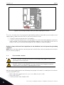
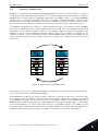
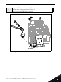
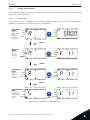
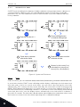
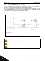
1.6 Grounding and earth fault protection
The VACON
®
20 CP AC drive must always be earthed with an grounding conductor connected to the
grounding terminal marked with .
Since the touch current exceeds 3.5 mA AC (for the three-phase version), according to EN61800-5-
1, the drive shall have a fixed connection and provision of an additional terminal for a second
protective grounding conductor of the same cross-sectional area as the original protective
grounding conductor.
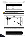
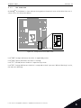
Three screws (for the three-phase version) are provided for: the ORIGINAL protective grounding
conductor, the SECOND protective conductor and the MOTOR protective conductor (the customer
can choose the screw for each one). See Figure 1 for the location of the three screws in the two
possible options available.
Figure 1. Protective grounding connections MS2 and MS3, three-phase version.
In VACON
®
20 CP, the phase conductor and the corresponding protective grounding conductor can
be of the same cross-sectional area, provided they are made of the same metal (because the cross-
sectional area of the phase conductor is less than 16 mm
2
).
CAUTION!

1
vacon • 10 Safety
Local contacts: http://drives.danfoss.com/danfoss-drives/local-contacts/
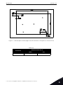
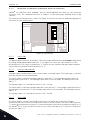
Figure 2. Protective grounding connections MS2, single-phase version.
The cross-sectional area of every protective grounding conductor which does not form a part of the
supply cable or cable enclosure shall, in any case, be not less than:
•2.5 mm
2
if mechanical protection is provided or
•4 mm
2
if mechanical protection is not provided. For cord-connected equipment, provisions
shall be made so that the protective grounding conductor in the cord shall, in the case of
failure of the strain-relief mechanism, be the last conductor to be interrupted.
However, always follow the local regulations for the minimum size of the protective grounding
conductor.
NOTE: Due to the high capacitive currents present in the AC drive, fault current protective switches
may not function properly.
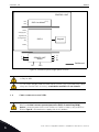
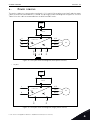
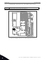
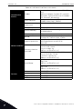
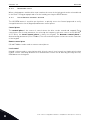
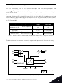
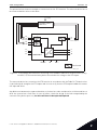
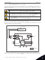
1.7 Insulation system
A distinction has to be made for the following three groups of terminals, according to the insulation
system of VACON
®
20 CP:
• Mains and motor connections (L1, L2, L3, U, V, W) or (L, N, U, V, W)
• Relays (R01, R02)
(**)
• Control terminals (I/Os, RS485, STO)
Please, consider carefully the insulation system depicted in Figure 2, before con-
necting any circuit to the unit.
The control unit of VACON
®
20 CP fulfils the insulation requirements of the stan-
dard IEC 61800-5-1 regarding DVC A circuits and also the strongest insulation
requirements of IEC 60950-1 regarding SELV circuits.

Safety vacon • 11
Local contacts: http://drives.danfoss.com/danfoss-drives/local-contacts/
1
The Control terminals (I/Os, RS485, STO) are isolated from the Mains (the insulation is reinforced,
according to IEC 61800-5-1) and the GND terminals are referred to PE.
This is important when you need to connect other circuits to the drive and test the complete
assembly. Should you have any doubts or questions, please contact your local distributor.
Figure 3. Insulation system (three-phase version).
POWER UNIT
L1
L2
L3
U
V
W
R01 __
R02 __
10Vref __
Analog Inputs __
Digital Inputs__
Analog Output __
24V __
RS485 __
STO __
Keypad
CONTROL UNIT
Reinforced
Mains
DVC A
DVC A or Mains
(**)
DC-
(*)
DC+/R+ R-

1
vacon • 12 Safety
Local contacts: http://drives.danfoss.com/danfoss-drives/local-contacts/
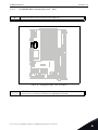
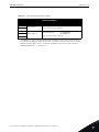
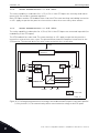
Figure 4. Insulation system (single-phase version).
1.8 Compatibility with RCDs
(*)
Only for MS3.
(**)
The relays may be used also with DVC A circuits. This is possible only if both
relays are used for DVC A circuitry: to mix Mains and DVC A is not allowed.
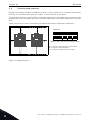
This product can cause a d.c. current in the protective grounding conductor.
Where a residual current-operated protective (RCD) or monitoring (RCM)
device is used for protection in case of direct or indirect contact, only an RCD or
RCM of Type B is allowed on the supply side of this product.
POWER UNIT
L
N
U
V
W
R01 __
R02 __
10Vref __
Analog Inputs __
Digital Inputs__
Analog Output __
24V __
RS485 __
Keypad
CONTROL UNIT
Reinforced
Mains
DVC A
DVC A or Mains
(**)
DC- DC+

Safety vacon • 13
Local contacts: http://drives.danfoss.com/danfoss-drives/local-contacts/
1
1.9 Cooling System
VACON
®
20 CP is available as a cold-plate solution. Customers have to enclose it in their own
housing and provide a suitable heatsink. However under maximum operating conditions the unit
should not exceed the following temperatures:
• Temperature around the polymeric enclosure (of VACON
®
20 CP): max. 70 °C (158 °F)
• Temperature at the cooling-plate (of VACON
®
20 CP): max. 85 °C (185 °F)
Please, contact your local distributor if you need further details or support to dimension the cooling
system in your final application.
NOTE: Up to 1.5 kW (Voltage range 380-480V) and 0.75 kW (Voltage range 208-240V) the drive is not
equipped with main cooling fan.
NOTE! You can download the English and French product manuals with applicable safety,
warning and caution information from https://www.danfoss.com/en/service-and-support/.
REMARQUE Vous pouvez télécharger les versions anglaise et française des manuels produit
contenant l’ensemble des informations de sécurité, avertissements et mises en garde
applicables sur le site https://www.danfoss.com/en/service-and-support/.

2
vacon • 14 Receipt of delivery
Local contacts: http://drives.danfoss.com/danfoss-drives/local-contacts/
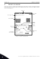
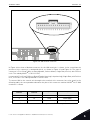
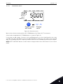
2. RECEIPT OF DELIVERY
Check the correctness of delivery by comparing your order data to the drive information found on
the package label. If the delivery does not correspond to your order, contact your supplier immedi-
ately. See paragraph 2.4.
Figure 5. VACON
®
package label.
44025325
M171600182
70SCO00343
Danfoss A/S, 6430 Nordborg, Denmark
P2:2.2kW:400 V / 3hp: 480 V
IP66
U2: 3AC 0-Input V 0-320 Hz, I2: 5.6 A
U1: 3AC 380-480 V 50/60 Hz, I1: 7.3 A
Made in Italy
POWER:
OUTPUT:
INPUT:
S.A.
VACON0020-3L-0006-4-X
170426
FW0117V012
Marks:
Cust. Ord. No:
Application:
Firmware:
B.ID:
S/N:
Code:
Type:
AC DRIVE
M171600182
70SC O00343
DANFOSS
Vacon type code
Rated
current
Supply
voltage
Application
code
EMC level
IP class
Serial number
Customer’s
order number
Vacon order
number
Batch ID

Receipt of delivery vacon • 15
Local contacts: http://drives.danfoss.com/danfoss-drives/local-contacts/
2
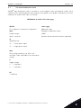
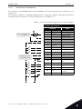
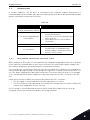
2.1 Type designation code
VACON
®
type designation code is formed of a nine-segment code and optional +codes. Each
segment of the type designation code uniquely corresponds to the product and options you have
ordered. The format of the code is as follows:
VACON0020-3L-0009-4-CP +xxxx +yyyy
VACON
This segment is common for all products.
0020
Product range:
0020 = Vacon 20
3L
Input/Function:
3L = Three-phase input
1L = Single-phase input
0009
Drive rating in ampere; e.g. 0009 = 9 A
See Table , Table and Table 41 for all the drive
ratings
4
Supply voltage:
2 = 208-240 V
4 = 380-480 V
CP
- Cold Plate
+xxxx +yyyy
Additional codes.
Examples of additional codes:
+DBIR
Dynamic Brake Internal Resistance (optional)

2
vacon • 16 Receipt of delivery
Local contacts: http://drives.danfoss.com/danfoss-drives/local-contacts/
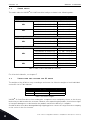
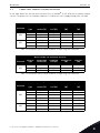
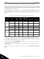
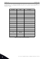
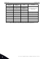
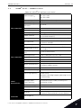
2.2 Order codes
The order codes for VACON
®
20 Cold Plate drive family are shown in the following table:
For all technical details, see chapter 7.
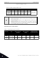
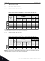
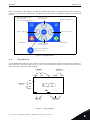
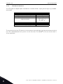
2.3 Unpacking and lifting the AC drive
The weights of the AC drives vary according to enclosure size. Note the weights of each individual
enclosure size in Table 4 below.
Table 4. Enclosure weights.
VACON
®
20 Cold Plate drives have undergone scrupulous tests and quality checks at the factory
before they are delivered to the customer. However, after unpacking the product, check that no signs
of transport damage are to be found on the product and that the delivery is complete.
Should the drive have been damaged during shipping, please contact the cargo insurance company
or the carrier in the first instance.
Enclosure size Order code Description
Supply voltage 3AC 208-240V
MS2
VACON0020-3L-0004-2-CP 0.75 kW - 1.0 HP drive
VACON0020-3L-0005-2-CP 1.1 kW - 1.5 HP drive
VACON0020-3L-0007-2-CP 1.5 kW - 2.0 HP drive
MS3
VACON0020-3L-0011-2-CP 2.2 kW - 3.0 HP drive
VACON0020-3L-0012-2-CP 3.0 kW - 4.0 HP drive
VACON0020-3L-0017-2-CP 4.0 kW - 5.0 HP drive
Supply voltage 1AC 208-240V
MS2
VACON0020-1L-0004-2-CP 0.75 kW - 1.0 HP drive
VACON0020-1L-0005-2-CP 1.1 kW - 1.5 HP drive
VACON0020-1L-0007-2-CP 1.5 kW - 2.0 HP drive
Supply voltage 3AC 380-480V
MS2
VACON0020-3L-0003-4-CP 0.75 kW - 1.0 HP drive
VACON0020-3L-0004-4-CP 1.1 kW - 1.5 HP drive
VACON0020-3L-0005-4-CP 1.5 kW - 2.0 HP drive
VACON0020-3L-0006-4-CP 2.2 kW - 3.0 HP drive
VACON0020-3L-0008-4-CP 3.0 kW - 4.0 HP drive
MS3
VACON0020-3L-0009-4-CP 4.0 kW - 5.0 HP drive
VACON0020-3L-0012-4-CP 5.5 kW - 7.5 HP drive
VACON0020-3L-0016-4-CP 7.5 kW - 10.0 HP drive
Table 3. Order codes of VACON
®
20 Cold Plate.
Enclosure Weight [kg] Weight [lb]
MS2 2 4.4
MS3 3 6.6

Receipt of delivery vacon • 17
Local contacts: http://drives.danfoss.com/danfoss-drives/local-contacts/
2
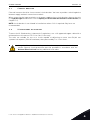
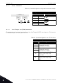
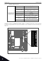
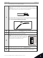
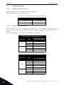
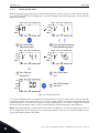
2.4 Accessories
After lifting the AC drive out, check that the delivery is complete and the following accessories are
included in the plastic bag:
Figure 6. STO connector.
2.4.1 Disposal
Item Quantity Purpose
STO terminal connector
*
*. Included only in the MS2 three-phase version and MS3.
1
Six pin black connector (see
Figure 6) to use STO function
M3.5 x 8 TapTite screw 4 Screws for control cable clamps
M1-3 Cable clamp 2 Clamping control cables
When the device reaches the end of its operating life do not
dispose of it as a part of standard household garbage. Main
components of the product can be recycled, but some need to
be fragmented to separate different types of materials and
components that need to be treated as special waste from
electrical and electronic components. To ensure
environmentally sound and safe recycling treatment, the
product can be taken to appropriate recycling center or
returned to the manufacturer.
Observe local and other applicable laws as they may mandate
special treatment for specific components or special
treatment may be ecologically sensible.

3
vacon • 18 Mounting
Local contacts: http://drives.danfoss.com/danfoss-drives/local-contacts/
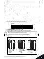
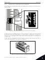
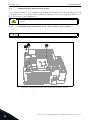
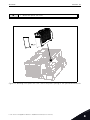
3. MOUNTING
The AC drive can be mounted on the wall or on the back plane of a cubicle. Ensure that the mounting
plane is relatively even. Both enclosure sizes can be mounted in any position (IP20 rating is
preserved only if mounted as in the following pictures). The drive shall be fixed with two screws (or
bolts, depending on the unit size).
3.1 Dimensions
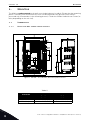
3.1.1 Enclosure MS2 three-phase version
Figure 7. VACON
®
20 Cold Plate, MS2 three-phase version.
Table 5.
Enclosure
Dimensions W x H x D
[mm] [in]
MS2 133.0 x 164.5 x 73.5 5.24 x 6.48 x 2.89
MS2 with plate 133.0 x 164.5 x 79.5 5.24 x 6.48 x 3.13

Mounting vacon • 19
Local contacts: http://drives.danfoss.com/danfoss-drives/local-contacts/
3
3.1.2 Enclosure MS2 single-phase version
Figure 8. VACON
®
20 Cold Plate, MS2 single-phase version.
Table 6.
Enclosure
Dimensions W x H x D
[mm] [in]
MS2 133.0 x 163.5 x 73.5 5.23 x 6.43 x 2.89
MS2 with plate 133.0 x 163.5 x 79.5 5.23 x 6.43 x 3.13

3
vacon • 20 Mounting
Local contacts: http://drives.danfoss.com/danfoss-drives/local-contacts/
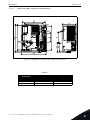
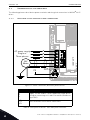
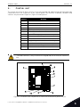
3.1.3 Enclosure MS3
Figure 9. VACON
®
20 Cold Plate, MS3.
Table 7.
Enclosure
Dimensions W x H x D
[mm] [in]
MS3 161.0 x 246.0 x 73.5 6.34 x 9.69 x 2.89
MS3 with plate 161.0 x 246.0 x 83.0 6.34 x 9.69 x 3.27
Page is loading ...
Page is loading ...
Page is loading ...
Page is loading ...
Page is loading ...
Page is loading ...
Page is loading ...
Page is loading ...
Page is loading ...
Page is loading ...
Page is loading ...
Page is loading ...
Page is loading ...
Page is loading ...
Page is loading ...
Page is loading ...
Page is loading ...
Page is loading ...
Page is loading ...
Page is loading ...
Page is loading ...
Page is loading ...
Page is loading ...
Page is loading ...
Page is loading ...
Page is loading ...
Page is loading ...
Page is loading ...
Page is loading ...
Page is loading ...
Page is loading ...
Page is loading ...
Page is loading ...
Page is loading ...
Page is loading ...
Page is loading ...
Page is loading ...
Page is loading ...
Page is loading ...
Page is loading ...
Page is loading ...
Page is loading ...
Page is loading ...
Page is loading ...
Page is loading ...
Page is loading ...
Page is loading ...
Page is loading ...
Page is loading ...
Page is loading ...
Page is loading ...
Page is loading ...
Page is loading ...
Page is loading ...
Page is loading ...
Page is loading ...
Page is loading ...
Page is loading ...
Page is loading ...
Page is loading ...
Page is loading ...
Page is loading ...
Page is loading ...
Page is loading ...
Page is loading ...
Page is loading ...
Page is loading ...
Page is loading ...
Page is loading ...
Page is loading ...
Page is loading ...
Page is loading ...
Page is loading ...
Page is loading ...
Page is loading ...
Page is loading ...
Page is loading ...
Page is loading ...
Page is loading ...
Page is loading ...
-
 1
1
-
 2
2
-
 3
3
-
 4
4
-
 5
5
-
 6
6
-
 7
7
-
 8
8
-
 9
9
-
 10
10
-
 11
11
-
 12
12
-
 13
13
-
 14
14
-
 15
15
-
 16
16
-
 17
17
-
 18
18
-
 19
19
-
 20
20
-
 21
21
-
 22
22
-
 23
23
-
 24
24
-
 25
25
-
 26
26
-
 27
27
-
 28
28
-
 29
29
-
 30
30
-
 31
31
-
 32
32
-
 33
33
-
 34
34
-
 35
35
-
 36
36
-
 37
37
-
 38
38
-
 39
39
-
 40
40
-
 41
41
-
 42
42
-
 43
43
-
 44
44
-
 45
45
-
 46
46
-
 47
47
-
 48
48
-
 49
49
-
 50
50
-
 51
51
-
 52
52
-
 53
53
-
 54
54
-
 55
55
-
 56
56
-
 57
57
-
 58
58
-
 59
59
-
 60
60
-
 61
61
-
 62
62
-
 63
63
-
 64
64
-
 65
65
-
 66
66
-
 67
67
-
 68
68
-
 69
69
-
 70
70
-
 71
71
-
 72
72
-
 73
73
-
 74
74
-
 75
75
-
 76
76
-
 77
77
-
 78
78
-
 79
79
-
 80
80
-
 81
81
-
 82
82
-
 83
83
-
 84
84
-
 85
85
-
 86
86
-
 87
87
-
 88
88
-
 89
89
-
 90
90
-
 91
91
-
 92
92
-
 93
93
-
 94
94
-
 95
95
-
 96
96
-
 97
97
-
 98
98
-
 99
99
-
 100
100


Danfoss VACON 20 Cold Plate Installation guide
- Type
- Installation guide
- This manual is also suitable for
Ask a question and I''ll find the answer in the document
Finding information in a document is now easier with AI
Related papers
-
Danfoss DST P92S Pressure transmitter SIL-2 Installation guide
-
Vacon VACON 20 X Installation guide
-
-
Vacon 100X series Installation guide
-
-
Vacon VACON® NXP CraneContr APFIFF33V077 User guide
-
Vacon NXP Grid Converter User guide
-
Vacon VACON® NXP GridConvert ARFIFF03V133 User guide
-
Vacon NXP Common DC Bus Installation guide
-
Other documents
-
Vacon 20 CP Installation guide
-
-
-
-
Mean Well FBA_4330929540 Installation guide
-
 Eyeboot EYE-600W-48V-12 Installation guide
-
-
 Tacens MS2 Datasheet
-
Vacon 100 FLOW User manual
-

