
User's Guide
Baumer MX Board Level Cameras (Gigabit Ethernet)
Document Version: v2.1
Release: 20.09.2017
Document Number: 11098023

2

3
Table of Contents
1. General Information ................................................................................................. 6
2. General safety instructions ..................................................................................... 7
3. Intended Use ............................................................................................................. 7
4. General Description ................................................................................................. 8
5. Camera Models ......................................................................................................... 9
6. Installation .............................................................................................................. 10
6.1 Environmental Requirements ................................................................................ 12
6.1.1 Heat Transmission .......................................................................................... 13
7. Pin-Assignment ...................................................................................................... 14
7.1 Power Supply and Digital IOs ............................................................................... 14
7.2 Gigabit Ethernet Interface (PoE) ........................................................................... 14
7.2.1 LED Signaling ................................................................................................. 14
8. ProductSpecications .......................................................................................... 15
8.1 Spectral Sensitivity for Baumer MXG Cameras .................................................... 15
8.2 Field of View Position ............................................................................................ 17
8.3 Acquisition Modes and Timings ............................................................................. 18
8.3.1 Free Running Mode ........................................................................................ 18
8.3.2 Fixed-Frame-Rate Mode ................................................................................ 19
8.3.3 Trigger Mode .................................................................................................. 20
8.3.4 Advanced Timings for GigE Vision
®
Message Channel .................................. 24
8.4 Software ................................................................................................................ 26
8.4.1 Baumer GAPI ................................................................................................. 26
8.4.2 3
rd
Party Software ........................................................................................... 26
9. Camera Functionalities .......................................................................................... 27
9.1 Image Acquisition .................................................................................................. 27
9.1.1 Image Format ................................................................................................. 27
9.1.2 Pixel Format ................................................................................................... 28
9.1.3 Exposure Time................................................................................................ 30
9.1.4 Fixed Pattern Noise Correction (FPNC) ........................................................ 31
9.1.5 High Dynamic Range (HDR) .......................................................................... 32
9.1.6 Look-Up-Table ................................................................................................ 33
9.1.7 Gamma Correction ......................................................................................... 33
9.1.8 Region of Interest ........................................................................................... 34
9.1.9 Binning............................................................................................................ 35
9.1.10 Brightness Correction (Binning Correction) .................................................. 38
9.1.11 Flip Image ..................................................................................................... 39

4
9.2 Color Processing ................................................................................................... 40
9.3 Color Adjustment – White Balance ....................................................................... 40
9.3.1 User-specic Color Adjustment ...................................................................... 40
9.3.2 One Push White Balance ............................................................................... 41
9.4 Analog Controls ..................................................................................................... 41
9.4.1 Offset / Black Level ......................................................................................... 41
9.4.2 Gain ................................................................................................................ 42
9.5 Pixel Correction ..................................................................................................... 43
9.5.1 General information ........................................................................................ 43
9.5.2 Correction Algorithm ....................................................................................... 44
9.5.3 Defectpixellist ................................................................................................. 44
9.6 Process Interface .................................................................................................. 45
9.6.1 Digital IOs ....................................................................................................... 45
9.6.2 IO Circuits ....................................................................................................... 46
9.6.3 Trigger ............................................................................................................ 47
9.6.4 Trigger Source ................................................................................................ 47
9.6.5 Debouncer ...................................................................................................... 48
9.6.6 Flash Signal .................................................................................................... 48
9.6.7 Timers ............................................................................................................. 49
9.6.8 Frame Counter ............................................................................................... 49
9.7 Sequencer ............................................................................................................. 50
9.7.1 General Information ........................................................................................ 50
9.7.2 Baumer Optronic Sequencer in Camera xml-le ............................................ 51
9.7.3 Examples ........................................................................................................ 51
9.7.4 Capability Characteristics of Baumer GAPI Sequencer Module .................... 52
9.7.5 Double Shutter ............................................................................................... 53
9.8 Device Reset ......................................................................................................... 53
9.9 User Sets .............................................................................................................. 54
9.10 Factory Settings .................................................................................................. 54
9.11 Timestamp ........................................................................................................... 54
10. Interface Functionalities ........................................................................................ 55
10.1 Device Information .............................................................................................. 55
10.2 Baumer Image Info Header (Chunk) ................................................................... 55
10.3 Packet Size and Maximum Transmission Unit (MTU) ......................................... 56
10.4 Inter Packet Gap ................................................................................................. 56
10.4.1 Example 1: Multi Camera Operation – Minimal IPG ..................................... 57
10.4.2 Example 2: Multi Camera Operation – Optimal IPG ..................................... 57
10.5 Transmission Delay ............................................................................................. 58
10.5.1 Time Saving in Multi-Camera Operation ...................................................... 58
10.5.2 Conguration Example ................................................................................. 59
10.6 Multicast .............................................................................................................. 61
10.7 IP Conguration .................................................................................................. 62
10.7.1 Persistent IP ................................................................................................. 62
10.7.2 DHCP (Dynamic Host Conguration Protocol) ............................................. 62
10.7.3 LLA ............................................................................................................... 63
10.7.4 Force IP ........................................................................................................ 63
10.8 Packet Resend .................................................................................................... 64
10.8.1 Normal Case................................................................................................. 64
10.8.2 Fault 1: Lost Packet within Data Stream ...................................................... 64
10.8.3 Fault 2: Lost Packet at the End of the Data Stream ..................................... 64
10.8.4 Termination Conditions ................................................................................. 65

5
10.9 Message Channel ............................................................................................... 66
10.9.1 Event Generation ......................................................................................... 66
10.10 Action Command / Trigger over Ethernet .......................................................... 67
10.10.1 Example: Triggering Multiple Cameras ...................................................... 67
11. Start-Stop-Behaviour ............................................................................................. 68
11.1 Start / Stop / Abort Acquisition (Camera)............................................................. 68
11.2 Start / Stop Interface ........................................................................................... 68
11.3 Acquisition Modes ............................................................................................... 68
11.3.1 Free Running ................................................................................................ 68
11.3.2 Trigger ........................................................................................................... 68
11.3.3 Sequencer .................................................................................................... 68
12. Cleaning .................................................................................................................. 69
13. Transport / Storage ................................................................................................ 69
14. Disposal .................................................................................................................. 69
15. Warranty Notes ....................................................................................................... 69
16. Support .................................................................................................................... 70
17. Conformity .............................................................................................................. 71
17.1 CE ....................................................................................................................... 71

6
1. General Information
Thanks for purchasing a camera of the Baumer family. This User´s Guide describes how
to connect, set up and use the camera.
Read this manual carefully and observe the notes and safety instructions!
Target group for this User´s Guide
This User's Guide is aimed at experienced users, which want to integrate camera(s) into
a vision system.
Copyright
Any duplication or reprinting of this documentation, in whole or in part, and the reproduc-
tion of the illustrations even in modied form is permitted only with the written approval of
Baumer. This document is subject to change without notice.
Classicationofthesafetyinstructions
In the User´s Guide, the safety instructions are classied as follows:
Notice
Gives helpful notes on operation or other general recommendations.
Caution
Pictogram
Indicates a possibly dangerous situation. If the situation is not avoided, slight
or minor injury could result or the device may be damaged.

7
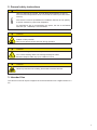
2. General safety instructions
Caution
Heat can damage the camera. Provide adequate dissipation of heat, to
ensure that the temperatures does not exceed the values (see Heat Trans-
mission).
As there are numerous possibilities for installation, Baumer do not speciy
a specic method for proper heat dissipation.
For applications with a corresponding free space, the use of the Baumer
heat sink (No. 11098288) is recommended.
Caution
Device heats up during operation.
Irritation of skin possible.
Don’t touch camera and/or heat sink during operation.
Caution
X°
Incorrect bending radius of the exprint cable.
An incorrect bending radius can damage the exprint cable.
Bend the exprint cable only up to a radius of 3 mm!
Caution
Observe precautions for handling electrostatic sensitive devices!
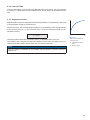
3. Intended Use
The camera is used to capture images that can be transferred over a GigE interface to a
PC.

8
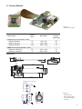
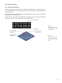
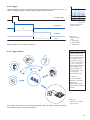
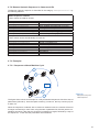
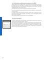
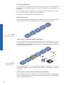
4. General Description
1
2
4
5
6
3
No. Description No. Description
1 Sensor print 4 Power supply
2 Flexprint cable 5 Ethernet Port
3 System print 6 Digital IO
All Baumer Gigabit Ethernet cameras of the MXG family are characterized by:
Best image quality ▪ Low noise and structure-free image information
▪ High quality mode with minimum noise
Flexible image acquisition ▪ Industrially compliant process interface with
parameter setting capability (trigger and ash)
Fast image transfer ▪ Reliable transmission up to 1000 Mbit/sec accord-
ing to IEEE802.3
▪ Cable length up to 100 m
▪ PoE (Power over Ethernet)
▪ Baumer driver for high data volume with low CPU
load
▪ High-speed multi-camera operation
▪ Gen<I>Cam™ and GigE Vision
®
compliant
Perfect integration ▪ Flexible generic programming interface (Baumer-
GAPI) for all Baumer cameras
▪ Powerful Software Development Kit (SDK) with
sample codes and help les for simple integration
▪ Baumer viewer for all camera functions
▪ Gen<I>Cam™ compliant XML le to describe the
camera functions
▪ Supplied with installation program with automatic
camera recognition for simple commissioning
Compact design ▪ Light weight
▪ exible assembly
Reliable operation ▪ State-of-the-art camera electronics and precision
mechanics
▪ Low power consumption and minimal heat genera-
tion

9
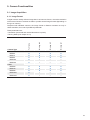
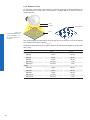
5. Camera Models
Camera Type
Sensor
Size
Resolution
Full
Frames
[max. fps]
CCD Sensor (monochrome / color)
MXG02 / MXG02c 1/4" 656 x 490 160
MXG12 / MXG12c 1/3" 1288 x 960 42
MXG20 / MXG20c 1/1.8" 1624 x 1228 27
CMOS Sensor (monochrome / color)
MXGC20 / MXGC20c 2/3" 2044 x 1084 55
MXGC40 / MXGC40c 1" 2044 x 2044 29
Dimensions
48
43,4
14
24
28,5
43,4
100
74,45
17,6
8
48
18,8
2x
M3/ 3
2,46/ 6
17,5
26
26
12
2x
M3/ 3
2,46/ 6
2x
M2/ 3
1,57/ 6
22,5
17,5
14,5
Ø 30
33
14,5
UN 1"-32 12
C-Mount adapter (optional)
2,7ø
4x
1,8ø
3x
◄Figure1
Baumer MXG camera.
◄Figure2
Dimensions of a
Baumer MXG camera
and C-Mount adapter
(optional)

10
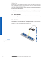
6. Installation
Caution
Observe precautions for handling electrostatic sensitive devices!
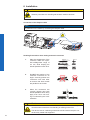
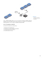
Connectionoftheexprintcable
Notice
Pay attention on the marks by connecting the exprint cable.
!
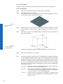
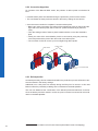
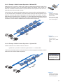
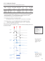
Handling Precautions when mating mounted connectors
1. Start the engagement of the
connector within the speci-
ed selfalignment range of
0.3 mm, while keeping the
boards parallel to each other.
3.0XAM3.0XAM
FX12*-**S-0.4SV
FX12*-**P-0.4SV
Fig.1
2. Do NOT start mating of the
mounted connectors at an
angle. Correctly position the
connectors over each other
an assure that both boards
are parallel to each other.
Incorrect Incorrect
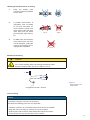
3. When the connectors are
correctly aligned (and both
boards paralell to each other)
apply even force until mat-
ing is conrmed by the "click"
sensation.
(0.5mm)(0.5mm)
Caution
When the connectors are mounted on the FPC, care should taken to pre-
vent the mated connectors from bending or twisting on the FPC.
The device case or cushioning material should be used to keep the con-
nectors fully mated and supported.

11
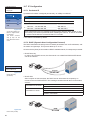
Handling Precautions when un-mating
1. Keep the boards (with
mounted connectors) parallel
to each other.
2. If parallel disconnection is
impossible, start un-mating
at one end, exercising ex-
treme caution to apply force
at the center of the connector
itself, away from the solder
joint rows (Ref. Fig A and Fig.
B).
Incorrect
Fig. A Fig. B
3. Do NOT start disconnection
at the sides as the connector
can be damaged, voiding the
warranty and making the re-
engagement impossible.
Incorrect
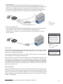
Mechanical mounting
Caution
X°
Incorrect bending radius of the exprint cable.
An incorrect bending radius can damage the exprint cable.
Bend the exprint cable only up to a radius of 3 mm!
B
A
Length from A to B = 94 mm
Lens mounting
Notice
Avoid contamination of the sensor and the lens by dust and airborne particles when
mounting the support or the lens to the device!
Therefore the following points are very important:
▪ Install the camera in an environment that is as dust free as possible!
▪ Keep the dust cover (bag) on camera as long as possible!
▪ Hold the print with the sensor downwards with unprotected sensor.
▪ Avoid contact with any optical surface of the camera!
◄Figure3
Bending radius of the
exprint cable

12
6.1 Environmental Requirements
Temperature
Storage temperature -10°C ... +70°C ( +14°F ... +158°F)
Operating temperature* see Heat Transmission
* If the environmental temperature exceeds the values listed in the table below, the cam-
era must be cooled. (see Heat Transmission)
Humidity
Storage and Operating Humidity 10% ... 90%
Non-condensing

13
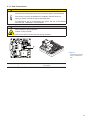
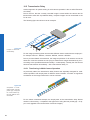
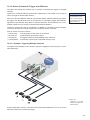
6.1.1 Heat Transmission
Caution
Heat can damage the camera. Provide adequate dissipation of heat, to
ensure that the temperature does not exceed the value in the table below.
As there are numerous possibilities for installation, Baumer does not
specify a specic method for proper heat dissipation.
For applications with a corresponding free space, the use of the Baumer
heat sink (No. 11098288) is recommended.
Caution
Device heats up during operation.
Irritation of skin possible.
Don’t touch camera and/or heat sink during operation.
T
Measure Point Maximal Temperature
T 70°C (158°F)
◄Figure4
Temperature measuring
points / installed heat
sink

14
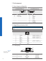
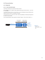
7. Pin-Assignment
7.1 Power Supply and Digital IOs
Power supply
(JST BM03B-SRSS-TB)
Digital IOs
(JST BM08B-SRSS-TB)
1
3
1
8
1 Shielding 1 Shielding
2 Power V
CC
2 IN 1
3 Power GND 3 GND IN
4 OUT 1
5 OUT 2
6 OUT 3
7 U
ext
OUT
8 Shielding
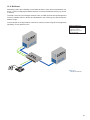
7.2 GigabitEthernetInterface (PoE)
Notice
The MXG supports PoE (Power over Ethernet) IEEE 802.3af Clause 33, 48V Power
supply.
8P8C mod jack with LEDs
18
1 (gn/wh) MX1+ (negative / positive V
port
)
2 (gn) MX1- (negative / positive V
port
)
3 (og/wh) MX2+ (positive / negative V
port
)
4 (bu) MX3+
5 (bu/wh) MX3-
6 (og) MX2- (positive / negative V
port
)
7 (bn/wh) MX4+
8 (bn) MX4-
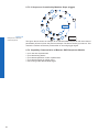
7.2.1 LED Signaling
1
2
LED Signal Meaning
1
green Link active
green ash Receiving
2 yellow Transmitting
Figure5►
LED positions on Baum-
er MXG cameras.

15
8. ProductSpecications
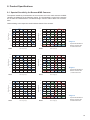
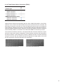
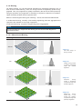
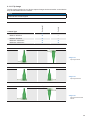
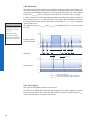
8.1 Spectral Sensitivity for Baumer MXG Cameras
The spectral sensitivity characteristics of monochrome and color matrix sensors for MXG
cameras are displayed in the following graphs. The characteristic curves for the sensors
do not take the characteristics of lenses and light sources without lters into consider-
ation.
Values relating to the respective technical data sheets of the sensors.
400 500 600 700 800 900 1000
0
0.2
0.4
0.6
0.8
1.0
Wave Length [nm]
Relative Response
MXG02
400 450 500 550 600 650
700
0
0.2
0.4
0.6
0.8
1.0
Wave Length [nm]
Relative Response
MXG02c
400 500 600 700 800 900 1000
0
0.2
0.4
0.6
0.8
1.0
Wave Length [nm]
Relative Response
MXG12
400 450 500 550 600 650
700
0
0.2
0.4
0.6
0.8
1.0
Wave Length [nm]
Relative Response
MXG12c
400 500 600 700 800 900
1000
0
0.2
0.4
0.6
0.8
1.0
Wave Length [nm]
Relative Response
MXG20
400 450 500 550 600 650
700
0
0.2
0.4
0.6
0.8
1.0
Wave Length [nm]
Relative Response
MXG20c
◄Figure6
Spectral sensitivities for
Baumer cameras with
0.3 MP CCD sensor.
◄Figure7
Spectral sensitivities for
Baumer cameras with
1,2 MP CCD sensor.
◄Figure8
Spectral sensitivities for
Baumer cameras with
2.0 MP CCD sensor.

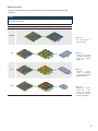
16
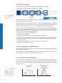
350 450 550 650 750 850 950 1050
Wave Length [nm]
Quantum Efficiency [%]
MXGC20/40
350 450 550 650 750 850 950 1050
Wave Length [nm]
Quantum Efficiency [%]
MXGC20c/40c
Figure9►
Spectral sensitivities
for Baumer cameras
with 2.0, 4.0 MP CMOS
sensor.

17
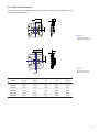
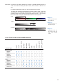
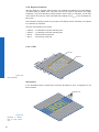
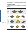
8.2 Field of View Position
The typical accuracy by assumption of the root mean square value is displayed in the
gures and the table below:
± XR
± YR
1,6± Z
± β
± α
MXG 02 / 12 / 20
MXGC 20 / 40
±YR
±XR
± α
1,94 ± Z
± β
Camera
Type
± x
R,typ
[mm]
± y
R,typ
[mm]
± α
typ
[°]
± β
typ
[°]
± z
typ
[mm]
MXG02 0,25 0,25 1,50 0,32 0,10
MXG12 0,17 0,17 1,50 0,32 0,10
MXG20 0,17 0,17 1,50 0,34 0,10
MXGC20 0,07 0,07 0,5 0,05 0,09
MXGC40 0,07 0,07 0,5 0,05 0,09
◄Figure10
Sensor accuracy of
Baumer MXG 02/12/20
◄Figure11
Sensor accuracy of
Baumer MXGC 20/40

18
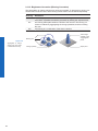
8.3 Acquisition Modes and Timings
The image acquisition consists of two separate, successively processed components.
Exposing the pixels on the photosensitive surface of the sensor is only the rst part of the
image acquisition. After completion of the rst step, the pixels are read out.
Thereby the exposure time (t
exposure
) can be adjusted by the user, however, the time need-
ed for the readout (t
readout
) is given by the particular sensor and image format.
Baumer cameras can be operated with three modes, the Free Running Mode, the Fixed-
Frame-Rate Mode and the Trigger Mode.
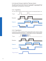
The cameras can be operated non-overlapped
*)
or overlapped. Depending on the mode
used, and the combination of exposure and readout time:
Non-overlapped Operation Overlapped Operation
Here the time intervals are long enough
to process exposure and readout succes-
sively.
In this operation the exposure of a frame
(n+1) takes place during the readout of
frame (n).
Exposur
e
Readout
Exposur
e
Readout
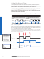
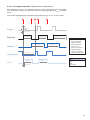
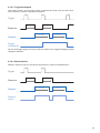
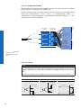
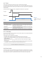
8.3.1 Free Running Mode
In the "Free Running" mode the camera records images permanently and sends them to
the PC. In order to achieve an optimal result (with regard to the adjusted exposure time
t
exposure
and image format) the camera is operated overlapped.
In case of exposure times equal to / less than the readout time (t
exposure
≤ t
readout
), the maxi-
mum frame rate is provided for the image format used. For longer exposure times the
frame rate of the camera is reduced.
Exposur
e
Readout
Flas
h
t
exposure(n)
t
flash(n)
t
flashdelay
t
flash(n+1)
t
readout(n+1)
t
readout(n)
t
exposure(n+1)
t
ash
= t
exposure
*) Non-overlapped means the same as sequential.
Image parameters:
Offset
Gain
Mode
Partial Scan
Timings:
A - exposure time
frame (n) effective
B - image parameters
frame (n) effective
C - exposure time
frame (n+1) effective
D - image parameters
frame (n+1) effective

19
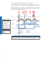
8.3.2 Fixed-Frame-Rate Mode
With this feature Baumer introduces a clever technique to the MXG camera series, that
enables the user to predene a desired frame rate in continous mode.
For the employment of this mode the cameras are equipped with an internal clock genera-
tor that creates trigger pulses.
Notice
From a certain frame rate, skipping internal triggers is unavoidable. In general, this de-
pends on the combination of adjusted frame rate, exposure and readout times.

20
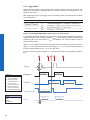
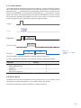
8.3.3 Trigger Mode
After a specied external event (trigger) has occurred, image acquisition is started. De-
pending on the interval of triggers used, the camera operates non-overlapped or over-
lapped in this mode.
With regard to timings in the trigger mode, the following basic formulas need to be taken
into consideration:
Case Formula
t
exposure
< t
readout
(1) t
earliestpossibletrigger(n+1)
= t
readout(n)
- t
exposure(n+1)
(2) t
notready(n+1)
= t
exposure(n)
+ t
readout(n)
- t
exposure(n+1)
t
exposure
> t
readout
(3) t
earliestpossibletrigger(n+1)
= t
exposure(n)
(4) t
notready(n+1)
= t
exposure(n)
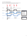
8.3.3.1 Overlapped Operation: t
exposure(n+2)
= t
exposure(n+1)
In overlapped operation attention should be paid to the time interval where the camera is
unable to process occuring trigger signals (t
notready
). This interval is situated between two
exposures. When this process time t
notready
has elapsed, the camera is able to react to
external events again.
After t
notready
has elapsed, the timing of (E) depends on the readout time of the current im-
age (t
readout(n)
) and exposure time of the next image (t
exposure(n+1)
). It can be determined by the
formulas mentioned above (no. 1 or 3, as is the case).
In case of identical exposure times, t
notready
remains the same from acquisition to acquisi-
tion.
Exposure
Readout
t
exposure(n)
t
readout(n+1)
t
readout(n)
t
exposure(n+1)
t
triggerdelay
t
min
Trigger
Flas
h
t
flash(n)
t
flashdelay
t
flash(n+1)
TriggerReady
t
notready
Image parameters:
Offset
Gain
Mode
Partial Scan
Timings:
A - exposure time
frame (n) effective
B - image parameters
frame (n) effective
C - exposure time
frame (n+1) effective
D - image parameters
frame (n+1) effective
E - earliest possible trigger
Page is loading ...
Page is loading ...
Page is loading ...
Page is loading ...
Page is loading ...
Page is loading ...
Page is loading ...
Page is loading ...
Page is loading ...
Page is loading ...
Page is loading ...
Page is loading ...
Page is loading ...
Page is loading ...
Page is loading ...
Page is loading ...
Page is loading ...
Page is loading ...
Page is loading ...
Page is loading ...
Page is loading ...
Page is loading ...
Page is loading ...
Page is loading ...
Page is loading ...
Page is loading ...
Page is loading ...
Page is loading ...
Page is loading ...
Page is loading ...
Page is loading ...
Page is loading ...
Page is loading ...
Page is loading ...
Page is loading ...
Page is loading ...
Page is loading ...
Page is loading ...
Page is loading ...
Page is loading ...
Page is loading ...
Page is loading ...
Page is loading ...
Page is loading ...
Page is loading ...
Page is loading ...
Page is loading ...
Page is loading ...
Page is loading ...
Page is loading ...
Page is loading ...
Page is loading ...
-
 1
1
-
 2
2
-
 3
3
-
 4
4
-
 5
5
-
 6
6
-
 7
7
-
 8
8
-
 9
9
-
 10
10
-
 11
11
-
 12
12
-
 13
13
-
 14
14
-
 15
15
-
 16
16
-
 17
17
-
 18
18
-
 19
19
-
 20
20
-
 21
21
-
 22
22
-
 23
23
-
 24
24
-
 25
25
-
 26
26
-
 27
27
-
 28
28
-
 29
29
-
 30
30
-
 31
31
-
 32
32
-
 33
33
-
 34
34
-
 35
35
-
 36
36
-
 37
37
-
 38
38
-
 39
39
-
 40
40
-
 41
41
-
 42
42
-
 43
43
-
 44
44
-
 45
45
-
 46
46
-
 47
47
-
 48
48
-
 49
49
-
 50
50
-
 51
51
-
 52
52
-
 53
53
-
 54
54
-
 55
55
-
 56
56
-
 57
57
-
 58
58
-
 59
59
-
 60
60
-
 61
61
-
 62
62
-
 63
63
-
 64
64
-
 65
65
-
 66
66
-
 67
67
-
 68
68
-
 69
69
-
 70
70
-
 71
71
-
 72
72


Ask a question and I''ll find the answer in the document
Finding information in a document is now easier with AI
Related papers
-
Baumer MXGC03C Quick start guide
-
-
Baumer VLG-22C.I User guide
-
Baumer HXG40c User guide
-
Baumer VLG-20M User guide
-
Baumer LXG-20M.PS User guide
-
Baumer LXG-200C User guide
-
Baumer HXC40c Operating instructions
-
-
Other documents
-
 SVS-Vistek eco415 User manual
-
Aim MXG Dash Logger User guide
-
Xerox 4050 IPS User manual
-
 opto engineering COE-290 User manual
-
-
Polaroid CSGS15BC23 User manual
-
Toshiba CSGS15BC23 User manual
-
Basler SCOUT LIGHT Owner's manual
-
 Arlight YM-801RA User manual
-


