Page is loading ...

INSTRUCTION MANUAL
Multi-Cylinder Four-Stroke Engines
FA-90R3
FA-170R3
FA-325R5-D
FA-200R3
FA-450R3-D
校了_斎藤製作所_MCFSE冊子cs3.indd 1 2010/11/04 10:01:46

VERY
IMPORTANT
Failure to read
and follow these
instructions before
you proceed may
result in engine
damage and the
voiding of your
warranty.
校了_斎藤製作所_MCFSE冊子cs3.indd 2 2010/11/04 10:01:47

INTRODUCTION
INTRODUCTION
Congratulations on your purchase
of a Saito 4-cycle engine. When
cared for properly, there high-
guality, finely crafted engines
offer many years of modeling
enjoyment.
This instruction manual has been
developed to ensure optimum per-
formance from the Saito engine
you've purchased. The instruc-
tions must be read thoroughly
prior to mounting and running the
engine.
SAFETY INSTRUCTIONS
This model engine will give you
considerable pleasure, satisfaction
and performance if you strictly
follow these safety instructions
and take heed of the warnings as
to its safe and proper use.
Remember at all times, THIS
ENGINE IS NOT A TOY, but
rather a precision-built machine
with more than enough power to
cause harm if misused or if the
safety precautions are not
observed.
Y
OU SHOULD ALWAYS:
1. When running the engine, be
sure that all spectators, especially
children, are at least 20 feet away.
2. Use the correct size and pitch
of propeller for your engine; refer
to the propeller chart in this man-
ual.
3. It is extremely important to bal-
ance the propeller prior to instal-
lation of the engine. Failure to do
so may cause damage to the Saito
engine and/or the airframe. Install
the propeller with the convex
(curved) side facing forward.
Securely tighten the propeller nut
against the washer and propeller.
A "jam" nut (or anti-loosening
nut) is suggested for all 4-cycle
engines.
4. Keep your face and body away
from the path of the propeller
blades when starting or running
your engine.
5. Never allow your hands to
come close to the propeller.
Utilize either a "Start stick"
or electric starter to start the
engine.
6. Make all carburetor abjust-
ments from behind the propeller.
7. To stop the engine, cut off fuel
supply (pinch or disconnect the
fuel line to the caeburetor),or use
the throttle linkage to shut off the
air.
1
校了_斎藤製作所_MCFSE冊子cs3.indd 1 2010/11/04 10:01:47

INTRODUCTION
2
DO NOT USE HANDS, FINGERS
OR ANY OTHER PART OF THE
BODY TO STOP THE
PROPELLER.
DO NOT THROW ANY OBJECT
INTO A PROPELLER TO STOP
IT!
8. Discard any propeller that is
nicked, scratched, cracked or
damaged in any way.
I
T IS HIGHLY RECOMMENDED THAT:
1. Safety glasses or goggles be
used when starting and running
your engine.
2. You do not run the engine in
the vicinity of loose gravel or
sand. The propeller may throw
such materials into your eyes.
The engine may also ingest these
harmful materials.
3. Loose clothing should be
avoided when operating your
model engine. Loose clothing can
become entangled in the propeller,
creating the possibility of bodily
harm. Also, all loose objects
(screwdrivers, pencils, nickel cad-
mium starters, stc.) Should be
removed from your pockets so
they do not fall into the propeller.
4. Glow plug clips and cords are
kept away from the propeller.
5. Your glow fuel is kept in a safe
place well away from sparks, heat
or anything that may ignite the
fuel.
B
EWARE:
1. Model engines get very hot
while running. Do not attempt to
handle the engine until it has
cooled.
2. Always run your model engines
in a well-ventilated area. Similar
to automotive engines, model
engines produce possibly harmful
carbon monoxide fumes.
3. Remember that model engines
produce a substantial amount of
power, more than enough to seri-
ously injure people and/or do con-
siderable damage to property.
Always use common sense, skill
and constant observation of safety
precautions.
2
校了_斎藤製作所_MCFSE冊子cs3.indd 2 2010/11/04 10:01:47

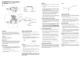
ENGINE PARTS IDENTIFICATION
DISASSEMBLY
The Saito multi-cylinder engines
are assembled using special jigs
and tools. As such, disassembly
should be performed only at the
factory anthorized service center.
If it becomes necessary to dis-
mantle the engine, such as after
a crash, please send your engine
to the authorized servise center:
Horizon Service Center
Attention: Saito Service
4105 Fieldstone Road
Champaign, IL 61822
(877-504-0233)
The engine has been assembled
with the use of special tools and
jigs to assure perfect assembly.
Disassembly of the engine will
result in the voiding of your war-
ranty.
ENGINE PARTS
IDENTIFICATION
It's important to be able to identi-
fy the parts of your Saito engines.
In this manual you'll find an
exploded view of Saito
multi-cylinder engines, as well as
a chart which includes part
numbers and descriptions. This
will assist you in easily and rapid-
ly identifying the respective parts
of your Saito engine.
SUPPORT EQUIPMENT
The following items, which are
not included with your Saito
engine, are necessary in order to
operate the model engine:
Fuel For maximum protec-
tion and longevity of Saito
engines, Saito manufacturing rec-
ommends a good quality airplane
fuel with 10
-
15% nitro methane,
such as Morgan Fuels, Omega,
Cool Power etc. Use of fuels
composed entirely of castor oil
is NOT recommended. A mix of
synthetic-castor oil is acceptable
and can be found in the various
fuel blends described above.
Propeller Refer to the
Propeller Selection Chaet, located
on page 15, to determine the best
initial propeller for your particular
applicatino.
Igniting Glow Plugs Your
glow plugs may be properly heat-
ed by several different sources.
The FA-90R3, FA-170R3, FA-
200R3, FA-325R5D, and FA-
450R3D all come with a wiring
harness kit that can be used
to provide several options for
providing heat to the glow plug.
3
校了_斎藤製作所_MCFSE冊子cs3.indd 3 2010/11/04 10:01:47

SUPPORT EQUIPMENT
The red connectors are the glow
plug cinnectors and there's one
black ground wire lead.
The red glow plug leads should be
connected to one another via a
common lead. Attach the glow
plug connectors to the rear glow
plugs.
N
OTE: The connectors should
firmly grip the glow plug stems.
If not, gently squeeze the clip
together with your fingers.
N
OTE: It is not necessary to ignite
all six of the glow plugs for the
FA-450 or all 10 of the glow plugs
for the FA-325. The front plugs
will ignite once the engine reaches
operating temperature. Attach the
black (ground) lead to the motor
mount. The FA-90R3, the FA-
170R3 and FA-200R3 have one
plug per cylinder.
1. On-Board Battery.
a. Solder the single common
lead from the glow plug connector
to the terminal of a 125V 10A
micro-switch (not supplied).
b. Solder a lead from the micro-
switch to the positive terminal on
the Ni-Cad battery.
c. Attach the single lead from
the ground wire to the negative
terminal on the Ni-Cad battery.
Please refer to Figure 1.
d. The on-board battery system
may be activated in two ways.
First, using a servo to activate the
switch, insert the servo lead into
the gear (or other toggle-activated
switch) channel in the receiver.
Adjust the travel of the selected
channel so that the servo arm
"trips" the micro-switch and
completes the circuit, heating the
glow plugs accordingly. Placing
the toggle switch in the opposite
position will break the circuit,
removing the heat from the glow
plugs.
Alternatively, the servo may be
connected to the throttle channel
or the receiver via a Y-harness.
Adjust the servo travel so that
Figure 1
4
校了_斎藤製作所_MCFSE冊子cs3.indd 4 2010/11/04 10:01:47

SUPPORT EQUIPMENT
contact with the micro-switch is
completed at the desired location
generally a low idle position.
2. Common Plug Activated
a. Solder the single lead from
the glow plug connectors to
one post of the female jack.
b. Attach the ground lead to the
remaining post on the female
jack.
To Glow Plug Connectors
c. Attach a male connector to
the positive and negative ter-
minals of your 1.5V starting
battery.
Refer to Figure 2.
3. Multi-Cylinder Glow Driver
There are many fine glow driver
units available on the market
today. Please follow the instruc-
tions included with the glow dri-
ver you've selected.
N
OTE: The use of an on-board
glow system is highly recom-
mended. This will guarantee a
smooth, reliable idle. If an
on-board glow system will NOT
be utilized, replacement of the
standard SAIP400S glow plugs
with a "hotter" plug, such as the
"Hangar 9 4-Cycle Super Plug
(HAN3011)" or equivalent,
is suggested.
Glow Plug Wrench Used to
remove and tighten glow plugs.
Manual or Electric Starter
For manual starts, a "Start stick"
(HAN113) is highly recommended.
Never use your fingers to start
any model engine as doing so
invites injury. There are a variety
of electric starters on the market.
The Hangar 9 Power Pro HD 12V
Starter(HAN162) works perfectly
on all Saito multi-cylinder engin-
es.
Figure 2
5
校了_斎藤製作所_MCFSE冊子cs3.indd 5 2010/11/04 10:01:47

BREAK-IN
BREAK-IN
The first run on any engine,
whether 2-cycle or 4-cycle, is crit-
ical to the future of the engine
itself. During this time, metal
mating parts (piston and cylinder,
ball bearings, etc.) wear in. Care
must be taken that the engine is
clean and free of any dust or grit
that may have accumulated while
building the model.
There are two accepted methods
for breaking in a new engine:
either running it mounted on a test
stand or in an aircraft. Either
method is acceptable; however,
mounting the engine to a test
stand allows the engine to be
observed throughout its operation,
as well as elevating it above the
ground and away from harmful
dust and dirt.
N
OTE: Because your engine may
have been sitting for an extended
period of time prior to running it,
a few drops of light oil applied
through the crankcase breather
nipple (19 on the exploded view),
if applicable, and down the
pushrod tubes (40) will ensure
proper lubrication for the first run.
Regardless of the mounting met-
hod chosen for break-in, the
following procedures are applicable:
1. Use a break-in fuel as
described in the "Support
Equipment" section, of
this manual.
2. Use the proper glow plugs.
Your engine includes the Saito
SAIP400S glow plugs, which are
standard replacement glow plugs
for these engines.
3. Select the correct propeller. To
do so, refer to the Propeller
Selection Chart on page 15 of this
manual.
4. Ensure that the high-speed nee-
dle valve (85) is opened (turned
counterclockwise) five full turns.
This guarantees a very rich set-
ting.
Do Not adjust the low-speed nee-
dle valve at this time. The low
speed needle valve is pre-adjusted
at the factory for initial break-in.
5. The use of a tachometer
(HAN111) is highly recommended
since the adjustment of a 4-cycle
engine, while similae to that of a
2-cycle engine, is more difficult to
"set by ear," making it easier to
damage the engine by "over lean-
ing."
6
校了_斎藤製作所_MCFSE冊子cs3.indd 6 2010/11/04 10:01:47

STARTING THE ENGINE
STARTING THE ENGINE
1. Make sure the glow plugs are
installed and tightened.
2. Be sure the propeller is proper-
ly secured. The use of an anti-
loosening or "jam nut" is encour-
aged on 4-cycle engines.
3. Make sure the fuel tank line(s)
are properly connected. The main
line should be connected to the
carburetor nipple on the carburetor
spray bar (82-1-2). The proper
"plumbing" of the lines is extreme-
ly important to the performance of
any angine.
4. Be certain the mufflers are
installed properly by oiling the
threads and inserting the crush
washers, and that the lines are
properly connected. See Figure 3
below.
5. Fill the fuel tank.
6. Check to make sure the glow
plugs are not connected to the
heat source (glow plug clip/lock-
ing socket).
N
OTE: If an electric starter will be
used to start the engine, it's not
necessary to prime the engine. To
do so may result in an engine
which becomes hydro-locked and
serious damage can occur.
7. Open throttle fully.
8. Close the choke valve (92), if
applicable (FA-450).
N
OTE: The FA-90R3, FA-170R3,
FA-200R3 and the FA-325R5D
require priming via a syringe.
(See page 8 text and diagrems)
9. Turn the prop one or two turns
clockwise to suck in the fuel (FA-
450 only).
10. Open the choke valve (92), if
applicable (FA-450).
Figure 3
7
校了_斎藤製作所_MCFSE冊子cs3.indd 7 2010/11/04 10:01:47

STARTING THE ENGINE
NOTE: The priming process for
the FA-90R3 and FA-90R3 and FA-
170R3 and FA-200R3 is described
as follows:For priming, inject the
approximate quantity of fuel (about
1-2cc) into the carburetor with a
syringe, etc. as illustrated below in
figure 4.
N
OTE: the priming process for the
FA-325R5D is described as fol-
lows:(See Figure 5)
For priming, inject the approxi-
mate quantity of fuel (about 1-2
cc) into the injection pipe on the
rear of the engine as illustrated.
After priming, be sure to install
the plug.
S
TART THE ENGINE:
11. Close the throttle to 1/4 to 1/3
open position.
12. Rotate the propeller clockwise
until it's against the compression
stroke.
13. Rotate the propeller in a coun-
terclockwise direction 2-3 times
(FA-170/FA-325). If much force
is needed to turn the propeller, the
fuel in cylinders 2 and 3 (for an
FA-90R3, FA-170R3, FA-200R3
and FA-450R3D; 2 and 5 for an
FA-325) is compressed. Remove
the glow plugs from these cylind-
ers and slowly rotate the propeller
clockwise to eject the excess fuel
via the cylinder heads.
14. Connect the heating source to
the glow plugs.
Figure 4
Figure 5
8
校了_斎藤製作所_MCFSE冊子cs3.indd 8 2010/11/04 10:01:48

STARTING THE ENGINE
NOTE: It's not necessary to ignite
all the plugs in a dual plug cylin-
der (two glow plugs per cylinder)
of Saito engines. It's only neces-
sary to apply heat to the rear
plugs; the front plugs will ignite
once the engine reaches operating
temperature.
N
OTE: A very common error is to
remove the glow plug igniter (or
on-board glow driver) too early.
It's suggested that the igniter be
left attached (or left on in the case
of an on-board glow driver) until
the engine has been run up and
the high-speed needle valve has
been properly adjusted.
15. Using either a "start stick" or
electric starter, spin the propeller
until the engine is running.
N
OTE: When using an electric
starter, care should be taken to be
sure that the engine does not
become "hydro-locked." While
the electric starter will turn the
engine over, it may damage the
connecting rod or other compo-
nents. If the engine becomes
hydro-locked, simply remove the
glow plugs and turn the engine
over a few times with the chicken
stick or electric starter. The excess
fuel will be forced to exit the
engine via the cylinder heads.
16. Initial break-in:
After the engine starts, open the
high speed needle valve slightly.
Do not exceed 4,000 rpm for the
first ten (10) minutes of operation.
This allows all parts to mate prop-
erly with good lubrication.
N
OTE: Due to the excessively
"rich" mixture setting, it may be
necessary to leave the heat source
attached (or left on) to the glow
plugs.
Subsequent runs may be made
while slightly leaning out the mix-
ture with each tank of fuel.
Generally, 40 minutes is consid-
ered sufficient for normal break-in
prior to the first flight.
N
OTE: FA-90R3 rotary units and
slide ways of the engine have
been lubricated at assembly with
black molybdenum oil to prevent
wearing or seizure. Hence, black
exhaust oil comes out of the
breather nipple and muffler at
break-in operation. This discharge
is not a sign of trouble and you
can continue flying.
9
校了_斎藤製作所_MCFSE冊子cs3.indd 9 2010/11/04 10:01:48

LOW SPEED CARBURETOR ADJUSTMENTS
17. After break-in:
If a test stand was used for the
break-in procedure, the engine
may now be mounted on the air-
craft using the integral motor
mount and mounting hardware
supplied with the Saito engine.
N
OTE: Always utilize the engine's
mounting spacers. Place the
mounting spacer between the inte-
gral motor mount and the firewall
of the aircraft. The spacers will
minimize firewall depression and
serve to reinforce the mount. Soft
mounting of Saito engines is not
required due to low vibration lev-
els found in the Saito multi-cylin-
der engines.(See Figure 6 Above)
The idle needle valve (89) can
now be fine tuned. Please refer to
the Low Speed Caeburetor
Adjustments Section on this page
for information on how to do this.
The valves can be checked at this
time. Refer to the Engine
Maintenance Section on page 12
for information on the valve
adjustment. The use of a tachome-
ter is encouraged for setting the
high-speed needle valve (85) prior
to flight. The peak rpm should be
obtained and then reduced by
approximately 200-300 rpm by
turning the high speed needle
valve counterclockwise.
LOW SPEED CARBURETOR
ADJUSTMENTS
The low speed, or idle needle
valve (89), is pre-adjusted at the
factory for best performance dur-
ing break-in. After break-in it may
be necessary to "fine tune" the
low speed adjustment using the
following procedure:
1. Start the engine and let it warm
up prior to attempting any adjust-
ments.
2. Close the throttle slowly and
adjust the low speed setting by
rotating the needle valve (89)
clockwise to lean the mixture and
counterclockwise to richen
the mixture.
N
OTE: The fuel mixture is too
rich when you open the throttle
rapidly and the engine emits white
Figure 6
10
校了_斎藤製作所_MCFSE冊子cs3.indd 10 2010/11/04 10:01:48

ENGINE PARTS IDENTIFICATION
smoke and "stutters" or "stumbles."
Correct this by rotating the idle
needle valve clockwise 1/4 to 1/2
turn at a time until the engine
transitions smoothly without hesi-
tation upon opening the throttle
rapidly. The fuel mixture may be
too lean when the engine stops
when the throttle is rapidly
opened from idle. Attempt to cor-
rect this by rotating the idle nee-
dle valve counterclockwise 1/4 to
1/2 turn at a time until the engine
transitions smoothly without hesi-
tation upon opening the throttle
rapidly. If the situation is not rec-
tified by counterclockwise rota-
tions of the idle needle valve, try
turning the idle needle valve
clockwise in 1/4 to 1/2 turn incre-
ments.
3. After obtaining the proper idle
setting, the low rpm setting can be
made through the positioning of
the throttle adjustment screw, if
applicable. If not, adjust the idle
setting via the throttle trim of
your transmitter.
NORMAL ENGINE
OPERATION
If break-in was accomplished on a
test bench, your engine is ready to
be mounted to the aircraft and
flown. The initial flight should be
performed with the engine adjust-
ed for a rich fuel mixture.
1. Your Saito engine should be
securely mounted to the aircraft
using the motor mount and hard-
ware kit provided. Soft mounting
of the Saito multi-cylinder
engines is not necessary due to
the extremely low vibration
level of these engines. Please
refer to Step 17 in the "Starting
the Engine" section for the proper
mounting procedure.
2. General operating procedures
which ensure long engine life are:
Do not operate the engine with
a "lean" mixture.
When installing the mufflers, oil
both the manifold threads and the
engine cylinder heads. Optional
flexible mufflers are available for
the FA-90R3, FA-170R3D and
FA-450R3D. An example of a con-
nection for the flexible mufflers is
shown in Figure7 below. Refer to
the Cross Reference Chart for the
part numbers for flexible mufflers.
Figure 7
11
校了_斎藤製作所_MCFSE冊子cs3.indd 11 2010/11/04 10:01:48

ENGINE MAINTENANCE
Regularly check all screws and
nuts on both the engine and muf-
fler.
After 1
-
2 hours of operation,
valve adjustment should be check-
ed. Adjust the valves as shown in
the Engine Maintenance Section.
The multi-cylinder engines are
equipped with a breather nipple.
It's recommended that a length of
silicone tubing be attached to this
crankcase breather nipple (19) for
routing away expelled oil from
the engine compartment.
ENGINE MAINTENANCE
Do not dismantle the engine.
The Multi-Cylinder Saito engines
are assembled utilizing special
jigs and tools. If it becomes
necessary to disassemble the
engine proper due to crash
damage or any other reason,
please forward your engine to
the Horizon Service Center.
Normal engine maintenance, such
as adjusting the valves or carbure-
tor maintenance, is permissible
without voiding the warranty;
however, disassembly of the
cylinders, crankshaft, and cam
gear assembly should be done
only by the Saito Service Center
because of the special jigs
andtools reguired. If you have any
questions concerning maintenance
procedures, please contact the
Horizon Service Center at:
(877-504-0233).
Our technicians will be happy to
advise you on maintenance issues.
Timing and cam gear alignment
should also be done by the Saito
Service Center.
After approximately one hour of
operation, tappet gap adjustment
may be necessary. Adjust the
valves to a clearance of
.03mm
-
.10mm (.002"
-
.004")
using the supplied gauge. The
valves must be adjusted with
the engine cold due to thermal
expansion.
N
OTE: Valves must be in the
closed position as shown in the
figure. When adjustment is com-
pleted, make sure you tighten the
lock nut. When you check the
valves, lubricate the moveable
parts. Also make sure screw is in
tight before making adjustment to
values.
Figure 8
12
校了_斎藤製作所_MCFSE冊子cs3.indd 12 2010/11/04 10:01:48

CARBURETOR MAINTENANCE
CARBURETOR
MAINTENANCE
Should you experience difficulty
with the carburetor of your
engine:
1. Remove the high speed needle
(85) and flush out the spray bar
with clean fuel. Replace the high
speed needle and follow the
instructions in the Low Speed
Carburetor Adjustment section.
2. Always use a high-quality
4-cycle glow plug. The SAIP400S
glow plug is highly recommended,
as well as the Hanger 9 Four Cycle
Super Plug (HAN3011).
TIPS FOR EXTENDED
ENGINE LIFE
To add longer life to your Saito
engine, we recommend the fol-
lowing:
1. Use a high quality airplane fuel,
such as Omega mix at 10
-
15%.
The use of all castor oil for
lubrication is not recommended.
A synthetic castor mix is the
preferred lubrication.
2. Use the recommended glow
plugs.
3. Use the proper propeller size and
balance the propeller prior to use.
4. Use a tachometer for precise
engine adjustments.
5. Use an "after-run" oil (EVOX-
1001) when you're finished flying
for the day.
6. For long-term storage, make
sure there is no fuel left in the
tank and the engine. Remove the
glow plug(s) and apply several
drops of high-quality oil (such
as Evolution Blue Block After
Run Oil (EVOX1001) to the top
of the engine, into the glow plug
hole, down the pushrod tubes, and
through the crankcase pressure
vent (breather nipple). Rotate the
crankshaft several times. Store
the engine in the box or on the
airplane with the nose down in
order to keep oil in the bearings.
TROUBLESHOOTING
Generally speaking, there are very
few things that will keep today's
modern glow engines from start-
ing. To that end, make sure you're
using high quality "fresh" fuel,
there are good glow plugs installed,
and the starting battery is charged
and in good condition. Should
the engine fail to start after these
items are verified, refer to the
following chart.
13
校了_斎藤製作所_MCFSE冊子cs3.indd 13 2010/11/04 10:01:48

TROUBLESHOOTING
S
YMPTOM
C
AUSE
C
OPRECTIVE
A
CTION
Engine fails to Start
Engine fires but
does not run
Engine starts but
slows down and
then stops
Engine starts,
speeds up, and
until then quits
Engine quits
when glow ignitor
is removed
Low voltage on starting
battery
Bad glow plug(s)
Insufficient priming
"Flooded" due to
excessive priming
Over primed
Mixture too rich
Mixture too lean
Mixture too rich
Incorrect glow plugs
Incorrect or bad fuel
Replace/recharge the
starting battery
Inspect/Replace bad
glow plugs
Repeat priming proce-
dure
Disconnect battery,
remove glow plugs and
rotate propeller several
times to "clear"
cylinder(s)
Disconnect battery and
rotate propeller several
times to "clear"cylin-
der(s)
Close high speed needle
1/2 turn and start again.
Repeat engine is run-
ning smoothly.
Open high speed needle
valve 1/2 turn and start
again.Repeat until engine
is running smoothly.
Close high speed needle
valve 1/2 turn and
restart.
Change glow plugs
Change fuel
In the event that none of the above procedures results in the engine run-
ning properly, contact our service departments for suggestions at:Horizon
Hobby, Inc. 4105 Fieldstone Road, Champaign, IL 61822
877-504-0233 (Mon
-
Fri 8:00
-
5:00 CST)
14
校了_斎藤製作所_MCFSE冊子cs3.indd 14 2010/11/04 10:01:48

ENGINE PARTS IDENTIFICATION
PROPELLER SELECTION
In the chart below is a propeller selection list. This chart enables you to
select the best propeller for initial set-up of your Saito engine.
Remember, it is imperative to balance each propeller prior to installation
onto your Saito engine. Failure to do so may cause unwanted vibration in
your aircraft.
You will note a letter (A,B,C, etc.) stamped on the top of the motor mount.
This letter identifies the production version of your engine. Should you
ever need to order a part or have a question pertaining to your engine,
specity this letter along with the engine type. This will allow for easier
identification of your engine.
SATIO MULTI CYLINDER PROPELLER CHART
NOTE: All recommendations are based on engines using APC props,
Power Master 15% 2-stroke fuel, and Saito SAIP400S glow plugs.
ENGINE:
FA-90R3 12X7 to 13X7
2,000 - 10,000
FA-170R3 15X8 to 16X8
2,000 - 9,500
FA-200R3 16X8 to 17X8
1,900 - 9,500
FA-325R5D 20X8 to 20X10
1,700 - 7,500
FA-450R3D
1,200 - 6,800 (w/On-Board Glow) 22X10, 22X12
1,600 - 6,800 (without On-Board) 24X8
glow system
15
校了_斎藤製作所_MCFSE冊子cs3.indd 15 2010/11/04 10:01:48

ENGINE SPECIFICATIONS
ENGINE SPECIFICATIONS
FUEL CONSUMPTION
FA-90R3
25cc per minute (15% Nitro, 13x6 propeller, full throttle)
FA-170R3
45cc per minute (15% Nitro, 15x8 propeller, full throttle)
FA-200R3
46cc per minute (15% Nitro, 16x8 propeller, full throttle)
FA-325R5D
75cc per minute (10% Nitro, 20x8 propeller, full throttle)
FA-450R3D
60cc per minute (15% Nitro, 22x10 propeller, full throttle)
OUTSIDE DIMENSIONS (MM)
Items
A B1 B2 C D E F G H I
FA90R3
50 20 38 129 156 58 60 69 168
ф
4.2
ф
FA170R3
94 25 49.5 155 186 74.5 77.5 79.5 198
ф
4.5
ф
FA200R3
94 25 49.5 155 186 74.5 77.5 79.5 198
ф
4.5
ф
FA325R5D
100 30 49 170 220 79 77 93 225
ф
5.2
ф
FA450R3D
110 30 49 200 237 79 100 100 250
ф
5.2
ф
SPECIFICATIONS
Items
Displacement Bore Stroke Weight K Cyl HP EX.
cu. in. (mm) (mm) (oz) (ISO) Dia
FA90R3 0.9/15.9cc 20 16 29.8 M7x1 AAC 0.95 M9xP0.75
FA170R3 1.7/27.8cc 24.8 19.2 46 M8x1.25 AAC 2.5 M10xP1
FA200R3 2.0/33cc 27 19.2 48.5 M8x1.25 AAC 2.7 M10xP1
FA325R5D 3.25 24.8 22.0 84 M8x1.25 ABC 3.8 M12xP1
FA450R3D 4.5/75cc 34 27.6 99 M10x1.25 AAC 5.5 M14xP1
NOTE: The FA170R3 and FA450R3D have muffler inserts that allow use of short pipes (standard issue)
that are 14mm. For use of flexible mufflers,remove the adapter nut installed in the cylinder.
Note: Measure ments correlate with chart.
L=Dia. of Thread of Ex. Pipes.
I=Dia. of Fitting Holes.
PART TT KK Y HH
FA-90R3 FA-170R3 FA-200R3 FA-325R5D FA-450R3D
01 Cylinder, Left 90R301 56GK01B 200R301 325R5D01C 450R3D01
02 Cylinder, Right * * * * *
06 Piston 30S06 5606 200R306 6506A 150S06
07 Piston Pin 30S07 6507 91807 6507 150S07
08 Piston Pin Retainer 30S08 6508 8008 6508 300T08
09 Piston Ring 60T09 6509 8009 6509 300T09
10 Connecting Rod 90R310 170R310 170R310 325R510 450R3D10A
11 Linked Conrod 90R311 170R311 170R311 325R511 450R3D11
12 Conrod Link pin & "E" clips * 170R312A 170R312A 325R512 450R3D12B
12-1 Link rod Pin & washer 90R312-1 * * * *
12-2 "E" Ring 90R312-2 * * * *
12-2B Link Rod pin & washer * * * * 450R3D12-2B
12-3B "E" Ring * * * * 450R3D12-3B
13 Connecting Rod Screw * * * * *
14 Cylinder Screw Set 90R314 5014 5014 5514 120S14
15 Crankcase 90R315 170R315 200R315 325R515A 450R3D15
16 Front Shield * * * 325R516 *
17 Rear Cover (a) 90R317 170R317 200R317 325R517 450R3D17
18 Rear Cover (b) 90R318 170R318 170R318 * 450R3D18
19 Breather Nipple 6519 6519 6519 5019 6519
20 Front Ball Bearing 6520A 120S20A 120S20A 300T20A 450R3D20
21 Main Ball Bearing * 300T21 300T21 * *
22 Rear Ball Bearing 6522A * * 300T22 450R3D22
23 Crankshaft 90R323A 170R323A 170R323A 325R523A 450R3D23A
24 Pinion-crankshaft * * * * *
25 Pinion gear pin * * * * *
26 Collar, Crankshaft * * * 325R526 *
27 Taper Collet & drv flange 6527 120S27 120S27 300T27B 450R3D27
28 Prop washer & nut 5628 170R328A 170R328A 170R328A 450R3D28
29 Prop Nut, spinner * 120S29 120S29 120S29 *
30 Prop Nut, Electric starter 5030 120S30 120S30 120S30 *
31 Crankcase screw set 90R331 170R331 170R331 325R531 450R3D31
32 Engine Gasket Set 40a321 170R332 170R332 325R532 450R3D32A
33 Cam Gear Housing 40a33 170R333 170R333 * 300T33
34 Cam Gear, Left * * * 325R534 *
35 Cam Gear, Right 30S35 6535A 6535A * 120S35
36 Cam Gear Shaft 90R336A 170R336A 170R336A 325R536 5036A
37 Teflon & Steel washer set 30S37 120S37 120S37 325R537 120S37
38 Tappet 30S38 5038 5038 5038 120S38
39 Pushrod 90R339 170R339 170R339 325R539 450R3D39
40 Pushrod cvt & rubber seal 90R340 60T40 200R340 325R540 450R3D40
41 Rocker Arm 60T41 5041 5041 5041 120S41
42 Rocker Arm screw & nut 5042 60T42 5042 5042 120S42
43 Rocker Arm pin 30S43 5043 5043 5043 120S43
44 Rocker Arm Bracket, left * * * * 150S44
45 Rocker Arm Bracket, Rt * * * * 150S45
46 Valve (in&out) pair 30S46 5646 5646 325R546 120S46
47 Viv sprg, kpr & retainer 30S47 5047 5047 325R547 120S47
48 Valve Retainer 5048 5048 5048 5048 120S48
49 Rocker Arm Cover 30GK49 50GK49 50GK49 120S49
50 Cam Gear Base(a) * * * 325R550A *
51 Cam Gear Base(b) * * * 325R551 *
52 Counter Gear * * * 325R552 *
53 Counter Gear Shaft * * * 325R553 *
54 Cam Gear Base Strut * * * 325R554A *
55 Impeller Fan * * * * *
56 Crank, Impeller * * * * *
57 Ball Bearing, Impeller Axle * * * * *
58 E-clip, Impller Ball Bearing * * * * *
64 Pump Assembly * * * * *
65 Air Pump Housing * * * * *
66 Diaphragm & Check Viv st * * * * *
67 Diaphragm, pushrod Rtn Sp * * * * *
68 Check valve in/out (pair) * * * * *
69 Intake Manifold, Left 90R369 170R369 200R369 325R569 *
70 Intake Manifold, Right
* * * * *
71 Intake Manifold Nut * * * 325R571 *
72 Intake Manifold w/Primer * * * * *
721 Intake Manifold w/Primer (Left)
325R5721 *
722 Intake Manifold w/Primer (Right)
325R5722 *
73 Muffler, Left 90R373 170R373 182TD73 450R3D73
74 Mufller, Right w/press 90R374 170R374 182TD74A 450R3D74
16
校了_斎藤製作所_MCFSE冊子cs3.indd 16 2010/11/04 10:01:49

PARTS LIST
PART TT KK Y HH
FA-90R3 FA-170R3 FA-200R3 FA-325R5D FA-450R3D
01 Cylinder, Left 90R301 56GK01B 200R301 325R5D01C 450R3D01
02 Cylinder, Right * * * * *
06 Piston 30S06 5606 200R306 6506A 150S06
07 Piston Pin 30S07 6507 91807 6507 150S07
08 Piston Pin Retainer 30S08 6508 8008 6508 300T08
09 Piston Ring 60T09 6509 8009 6509 300T09
10 Connecting Rod 90R310 170R310 170R310 325R510 450R3D10A
11 Linked Conrod 90R311 170R311 170R311 325R511 450R3D11
12 Conrod Link pin & "E" clips * 170R312A 170R312A 325R512 450R3D12B
12-1 Link rod Pin & washer 90R312-1 * * * *
12-2 "E" Ring 90R312-2 * * * *
12-2B Link Rod pin & washer * * * * 450R3D12-2B
12-3B "E" Ring * * * * 450R3D12-3B
13 Connecting Rod Screw * * * * *
14 Cylinder Screw Set 90R314 5014 5014 5514 120S14
15 Crankcase 90R315 170R315 200R315 325R515A 450R3D15
16 Front Shield * * * 325R516 *
17 Rear Cover (a) 90R317 170R317 200R317 325R517 450R3D17
18 Rear Cover (b) 90R318 170R318 170R318 * 450R3D18
19 Breather Nipple 6519 6519 6519 5019 6519
20 Front Ball Bearing 6520A 120S20A 120S20A 300T20A 450R3D20
21 Main Ball Bearing * 300T21 300T21 * *
22 Rear Ball Bearing 6522A * * 300T22 450R3D22
23 Crankshaft 90R323A 170R323A 170R323A 325R523A 450R3D23A
24 Pinion-crankshaft * * * * *
25 Pinion gear pin * * * * *
26 Collar, Crankshaft * * * 325R526 *
27 Taper Collet & drv flange 6527 120S27 120S27 300T27B 450R3D27
28 Prop washer & nut 5628 170R328A 170R328A 170R328A 450R3D28
29 Prop Nut, spinner * 120S29 120S29 120S29 *
30 Prop Nut, Electric starter 5030 120S30 120S30 120S30 *
31 Crankcase screw set 90R331 170R331 170R331 325R531 450R3D31
32 Engine Gasket Set 40a321 170R332 170R332 325R532 450R3D32A
33 Cam Gear Housing 40a33 170R333 170R333 * 300T33
34 Cam Gear, Left * * * 325R534 *
35 Cam Gear, Right 30S35 6535A 6535A * 120S35
36 Cam Gear Shaft 90R336A 170R336A 170R336A 325R536 5036A
37 Teflon & Steel washer set 30S37 120S37 120S37 325R537 120S37
38 Tappet 30S38 5038 5038 5038 120S38
39 Pushrod 90R339 170R339 170R339 325R539 450R3D39
40 Pushrod cvt & rubber seal 90R340 60T40 200R340 325R540 450R3D40
41 Rocker Arm 60T41 5041 5041 5041 120S41
42 Rocker Arm screw & nut 5042 60T42 5042 5042 120S42
43 Rocker Arm pin 30S43 5043 5043 5043 120S43
44 Rocker Arm Bracket, left * * * * 150S44
45 Rocker Arm Bracket, Rt * * * * 150S45
46 Valve (in&out) pair 30S46 5646 5646 325R546 120S46
47 Viv sprg, kpr & retainer 30S47 5047 5047 325R547 120S47
48 Valve Retainer 5048 5048 5048 5048 120S48
49 Rocker Arm Cover 30GK49 50GK49 50GK49 120S49
50 Cam Gear Base(a) * * * 325R550A *
51 Cam Gear Base(b) * * * 325R551 *
52 Counter Gear * * * 325R552 *
53 Counter Gear Shaft * * * 325R553 *
54 Cam Gear Base Strut * * * 325R554A *
55 Impeller Fan * * * * *
56 Crank, Impeller * * * * *
57 Ball Bearing, Impeller Axle * * * * *
58 E-clip, Impller Ball Bearing * * * * *
64 Pump Assembly * * * * *
65 Air Pump Housing * * * * *
66 Diaphragm & Check Viv st * * * * *
67 Diaphragm, pushrod Rtn Sp * * * * *
68 Check valve in/out (pair) * * * * *
69 Intake Manifold, Left 90R369 170R369 200R369 325R569 *
70 Intake Manifold, Right
* * * * *
71 Intake Manifold Nut * * * 325R571 *
72 Intake Manifold w/Primer * * * * *
721 Intake Manifold w/Primer (Left)
325R5721 *
722 Intake Manifold w/Primer (Right)
325R5722 *
73 Muffler, Left 90R373 170R373 182TD73 450R3D73
74 Mufller, Right w/press 90R374 170R374 182TD74A 450R3D74
PART TT KK Y HH
FA-90R3 FA-170R3 FA-200R3 FA-325R5D FA-450R3D
78 Muffler, Complete Set * 170R378 170R378 325R578B *
781 Flex Muffler #1 Cylinder, 250mm
90R3781 170R3781 170R3781 (see 78B1 (see 1111
782 Flex Muffler #2 Cylinder, 100mm
90R3782 170R3782 170R3782 thru 78B6A thru 1113
783 Flex Muffler #3 Cylinker, 265mm
90R3783 * * below) below)
786 Cable Tie 170R3786 170R3786 170R3786 * *
79 Muffler Gasket 90R379 5079 5079 325R579 450R3D79
80 Muffler Nut 90R380 325R580 325R580 450R3D80
81 Priming Harness * * * 325R581
82 Carburetor, Complete * * * *
821 Carburetor, Complete (left) 90R3821
170R3821A 170R3821A
325R5821A 450R3D821D
822 Carburetor, Complete (rt) * * * * *
831 Carburetor Body Assy, lft 90R3831 170R3831 170R3831 325R5831 450R3D831A
832 Carburetor Body Assy, rt * * * * *
83 Carburetor Body Assembly * * * * *
84 Spray Bar Assembly * * * * 450R3D84A
85 High Speed Needle Valve 60T85 60T85 60T85 10085 120S85
86 High Speed NV Extension 5086 5086 5086 5086 5086
87 Throttle Barrel Assembly 90R387 170R387A 170R387A 325R587A 325R587B
88 Throttle Lever 5088B 5088B 5088B 325R588A 5088B
89 Idle Needle Valve 170R389 170R389 170R389 5089 120S89
90 Carb Screw & Spring set 170R390 170R390 170R390 325R590 120S90A
91 Carburetor Gasket set 325R591 325R591 325R591 325R591 300TTDP91
92 Choke Valve Assembly * * * * 450R3D92
93 Intake Velocity Stack * * * * *
94 Glow Plug Harness 170R394 170R394 170R394 325R594 450S3D94
95 Engine Mount 90R395 170R395 170R395 325R595A 325R595A
96 Tool Set 90R396 170R396 170R396 325R596 450R3D96
97 Instruction Manual SAIMAN3 SAIMAN3 SAIMAN3 SAIMAN3 SAIMAN3
99 Muffler Bracket * * * * *
101 Twin Carb Control Assy * * * * *
102 Fuel Pump System * * * * *
103 Carb fitting flange w/screw * * * * 450R3D103
104 Cam Gear Bearing, rear * * * * *
105 Cam Gear Bearing, Front * * * * *
106 Cam Gear Bearing, Shield * * * * *
107 Carburetor Bracket * * * * *
109 F-1 Fuel Filter 50109 50109 50109 50109 50109
110 Anti-loosening prop nut 56110 170R3110 170R3110 170R3110 300T110
1111 Muffler #1 Cyl. 350mm * * * * 450R3D1111
1112 Muffler #2 Cyl. 195mm w/nipple
* * * * 450R3D1112
1113 Muffler #3 Cyl. 250mm * * * * 450R3D1113
116 M3 Nut for Spinner * * * * *
117 M4 Nut for Spinner 65117 120S117 120S117 120S117 *
118 M5 Nut for Spinner 65118 120S118 120S118 120S118 *
119 Rear Cover w/intg Motor M * * * * *
120 Saito Glow Plug SAIP400S SAIP400S SAIP400S SAIP400S SAIP400S SAIP400S
121 Crank Pin Spacer, Teflon 90R3121 170R3121 170R3121 325R5121 450R3D121
122 Spray Bar /"O" ring 170R3122 170R3122 170R3122 325R5122 *
123 Rubber bush for PR cvr (U) 50123 50123 50123 50123 120S123
124 Rubber bush for PR cvr (L) 50124 50124 50124 50124 120S124
125 Muffler * * * * *
126 Needle Stopper & Nut 50126 50126 50126 50126 120S126
128 Heat Sink * * * * 450R3D128
129 Lub adaptor/set screw M4x4 * * * * 450R3D129
130 Muffler, Adaptor Nut * 170R3130 170R3130 * 450R3D130
131 Throttle Valve ext adaptor 90R3131 170R3131 170R3131 * *
135 Prop wash/nut/anti-loos nut 56135 170R3135 170R3135 170R3135 450R3D135
136 Intake Manifold /nut 450R3D136A
139 Valve Guide 30S139 50139 50139 65139 120S139
78B1 Flex Muf, #1 Cyl. 345mm * * * 325R578B1 *
78B2 Flex Muf. #2 Cyl. 265mm * * * 325R578B2 *
78B3 Flex Muf, #3 Cyl. 155mm * * * 325R578B3 *
78B4 Flex Muf. #4 Cyl. 285mm * * * 325R578B4 *
78B5 Flex Muf. #5 Cyl. 355mm * * * 325R578B5 *
78B6A Cable Tie, Muffler * * *
325R578B6A
*
140 Muffler Rt Angle Adaptor * 100Ti140 100Ti140 65140 120S140
141 Complete Impeller Unit
* * * 325R5141 *
143 Flex Exhaust Pipe w/2 nuts * 50143 50143 65143 120S143
144 Upgraded Carburetor rebuild kit
* * * * *
145 Spray Bar w/Internal P-2 "O" ring
* * * * 120S145
147 Carburetor Nipple 30S147 30S147 30S147 30S147 30S147
MULTI-CYLINDER CROSS REFERENCE CHART
17
校了_斎藤製作所_MCFSE冊子cs3.indd 17 2010/11/04 10:01:50

PARTS LIST
FA-90R3
18
校了_斎藤製作所_MCFSE冊子cs3.indd 18 2010/11/04 10:01:50
/