
_NSTALLAT_ON AND SERVICE MUST BE PERFORMED BY
A QUAUHED _NSTALLER.
IMPORTANT: SAVE FOR LOCAL ELECTRICAL _NSPECTOR'S USE.
READ AND SAVE THESE _NSTRUCT_ONS FOR FUTURE REFERENCE.
if the information in this manual is not followed exactly, a fire or explosion may result
causing property damage, personal iniury or death.
FOR YOUR SAFETY:
J Do not store or use gasoline or other flammable vapors and liquids in the vicinity of this or any other
J WHAT TO DO iF YOU SMELL GAS:
Do not try to light any appliance.
Do not touch any electrical switch; do not use any phone in your building.
Immediately call your gas supplier from a neighbor's phone. Follow the gas suppHer's instructions.
* ff you cannot reach your gas supplier, call the fire department.
J Installation and service must be performed by a qualified installer, service agency or the gas supplier.
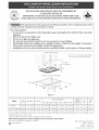
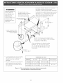
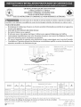
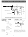
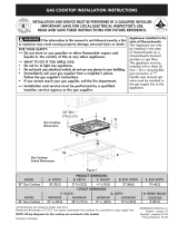
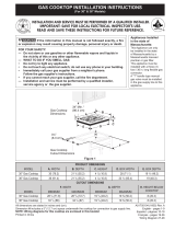
Cooktop Dimensions
* 30" min. for unprotected cabinet
24" min. for protected surface
1
30" Min.*
(76.2 cm) Min.*
C
Cooktop Cutout Dimensions
Figure 1
B.WIDTH C. DEPTH '
. LENGTH..
30" Models 30 (76.2) 21 Y2(54.6) 3 I/s (7.9)
36"X 21Y2"Models 36(91.4) 21 Y2(54.6) 3Vs(7.9)
36"X 18" Models 36 (91.4) 18 (45.7) 3 Y2(8.9)
MIN, D. LENGTHMAX.
26 s/s(67.6) 267/s (68.3)
32 34(83.2) 33 (83.8)
34 1/4(87) 34 s/s(87.3)
MIN. E. WIDTH MAX:
19 (48.3) 19 3/s(49.2)
19 (48.3) 19 S/s(49.2)
16 s/s(42.2) 16 3A(42.5)
E DEPTH
BELOW
COOKTOP_ (Min.) . (Min.)
5 (12.7) 23A(7) 2Y4(5.7)
5 (12.7) 23A(7) 2Y4(5.7)
5 (12.7) 4Y4(10.8) 3 (7.6)
All dimensions are in inches (cm).
Dimension Fisfor clearance under cooktop for gas connection.
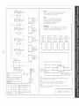
NOTE: Wiring diagrams for these appliances are enclosed in this booklet.
Only some models are available in Canada.
', Recycled paper
P/N 318201450 (0410) Rev B
English - pages 1-8
Espanol- pages 9-17
Franqais - pages 18-26
Wiring Diagrams - pages 27-28

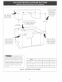
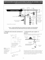
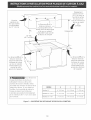
!3" (33 cm)
Max, Depth For
Cabinet Installed
Above Cooktop.
18" Min,
(45.7cm Min.)
A Min.
Dimensions J isthe Minimum
Distance Required Between Rear
of Cooktop to Adjacent
Combustible Surfaces.
30" (76.2 cm) Min,
Clearance Between
the Top of the
Cooking Platform
and Unprotected
Wood or Metal
Cabinet
4
Clearance
Dimension K isthe
Minimum Clearance
Required From Left
Side To Adjacent
Combustible Surface.
Dimension H istile
Minimum Clearance
Required From Right
Side To Adjacent
Combustible Surface.
To eliminate the risk of
burns or fire by reaching over heated
surfaces, cabinet storage space located
above the cooktop should be avoided. If
cabinet storage is provided, risk can be
reduced by installing a range hood that
projects horizontally a minimum of 5"
(12.7 cm) beyond the bottom of tile
cabinets.
30" Models 4" (10.2 cm) 1 _/_"(3.8 cm) 7" (17.8 cm)
36" X 21_/_" Models 5" (12.7 cm) 1 _/_"(3.8 cm) 5" (12.7 cm)
36" X 18" Models 3" (7.6 cm) 3 3A" (9.5 cm) 3" (7.6 cm)
Figure 2 - COUNTERTOP CUTOUT OPENING

Important Notes to the Installer
1. Readallinstructionscontainedintheseinstallation
instructionsbeforeinstallingthecooktop.
2. Removeallpackingmaterialbeforeconnectingtile
electricalsupplytothecooktop.
3. Observeallgoverning(:odesandordinances.
4. Besuretoleavetheseinstructionswithtileconsumer.
important Note to the Consumer
KeeptheseinstructionswithyourUseandCare Guide for
future reference.
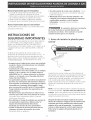
IMPORTANT SAFETY
INSTRI
Installation of this cooktop must conform with local codes
or, in the absence of local (:odes, with tile National Fuel
Gas Code ANSI Z223.1--1atest edition in the United
States, or in Canada, with the Canadian Fuel Gas Code,
CAN/CGA B149 and CAN/CGA B149.2.
This cooktop has been design certified by American Gas
Association(A.G.A.). As with any appliance using gas
and generating heat, there are certain safety precautions
you should follow. You will find them in tile Use and
Care Guide, read it carefully.
Be sure your cooktop is installed and grounded
properly by a qualified installer or service
technician.
• This cooktop must be electrically grounded in
accordance with local codes or, in their absence,
with the National Electrical Code ANSI/NFPA No,
70--Jatest edition in the United States, or in
Canada, with the Canadian Electrical Code, CSA
C22.1 Part 1.
• The burners can be tit manuatly during an
electrical power outage. To light a burner, hold a
tit match to the burner head, then slowly turn the
Surface Control knob to LJTE. Use caution when
tighting burners manually.
• Do not store items of interest to children in the
cabinets above the cooktop, Children could be
seriously burned climbing on the cooktop to reach
items.
• To eliminate the need to reach over the surface
burners, cabinet storage space above the burners
should be avoided.
Adjust surface burner flame size so it does not
extend beyond the edge of the cooking utensil,
Excessiveflame is hazardous.
Never use your cooktop for warming or heating
the room. Prolonged use of the cooktop without
adequate ventilation can be hazardous.
• Do not store or use gasotine or other flammable
vapors and liquids near this or any other
appliance. Explosions or fires could result.
The electrical power to the cooktop
must be shut off while line connections are being
made, Failure to do so could result in serious
injury or death.
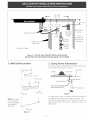
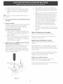
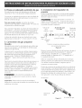
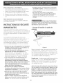
1. Before Installing the Cooktop
Foam Tape
Figure 3
A roll of foam tape is supplied loose and packed in tile
literature package. Install the foam around the
perimeter of the flange of the burner box, at a distance
of 1/4"(0.6 cm) from the edge of the glass or porcelain
top. Apply the exposed adhesive side of the tape
against the underside of the glass or the burner box
surface (see figure 3).
NOTE: This tape seals the underside of the cooktop to
the counter. Do not remove this foam tape. This
tape prevents entry of air for normal gas combustion,
and prevents liquids from leaking under the cooktop.
After inserting the cooktop into the countertop
opening, make sure the unit is sitting on the metat
flange around the top of the burner box. Cooktop
must not sit on the glass or porcelain top. Avoid
cutting an oversized hole in the countertop.
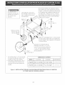
3

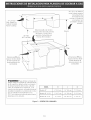
All mounting hardware
must be used to secure
the builtqn oven to the
cabinets. Refer to the
builtqn oven installa-
tion instructions.
208/240 Volt grounded
junction box for builtqn
oven,
This cooktop may be in-
stalled over certain built-
in electric oven models.
Approx. 3"
(7.6cm)
4 1/2"Max.*
(11.4 cm Max.*)
Side filler panels are necessaryto isolate the
unit from adjoining cabinets. Panel height
should allow for installation of approved
cooktop models. See "Typical Gas Cooktop In-
stallation Over an Electric Builtqn Oven Installed
Under the Counter" in this booklet.
32" Min.**
(81.3 cm Min.**)
36" Min. /_
(91.4 cm Min.)
Use 3A"(1.9 cm) plywood, installed on two
runners, flush with toe plate. Must be capable
of supporting 150 Ibs (68 kg).
Cut an opening in wood basemini-
mum 9" x 9" (22.9 cm X 22.9 cm),
2" (5.1 cm) from left side filler
panel, to route armoured cable to
junction box.
* If no cooktop is installed directly over
the oven unit, 5" (!2.7 cm) maximum
isallowed.
** 32" (8! .3 cm) rain. from top of cabinet
to top of runners must be maintained.
CUTOUT DIMENSIONS
MODEL' E, HEIGHT I F,WIDTH' G. DEPTH
27" (68,6 cm) 28 I/8" (71 4 cm) Min 247/8" (63,2 cm) Min
23 1A"(59 7 cm)
Wall Oven 28 Vg" (72,7 cm) Max 25 V4" (64,1 cm) Max
30" (76,2 cm) 28 _¼"(718 cm) Min 28 Vz" (72,4 cm) Min
Wall Oven 28718``(7:3.3 crn) Max. 29" (7:3.7 crn) Max. 24" (61 crn)
Figure 4 - TYPICAL UNDER COUNTER INSTALLATION OF AN ELECTRICBUILT-IN OVEN
WITH COOKTOP MOUNTED ABOVE

18" Max.
(45.7 cm)
Flexible
Wall Oven Cabinet
5" Max. 6 Y2" Min.
Flare (1271cm) (If_:m)
Flare
Union
Cabinet sides or
filler panel
120V/6OHz
Grounded
Outlet
Pressure
Regulator
Manual
Shutoff
Valve
4" (_0.2 cm)
Right Side of
Cabinet
(To be
accessible for
shut-off valve
operation)
Figure 5 - TYPICAL GAS COOKTOP INSTALLATION OVER
AN ELECTRICBUILT-IN OVEN INSTALLED UNDER THE COUNTER
2. Wall Outlet Location
12" (30.5 cm)
I 10" (25.4 cm)
: i
i Recommende
' 120V grounded outlet on
I rear wall
22"
(55.9 cm)
CL of unit
NOTE: If an outlet
is not available,
have one installed
by a qualified
technician.
I
I
"CL of unit
Figure 6
3. Cramp Down Information
Once the cooktop is installed in the counter opening, you
must clamp the unit down as shown.
Countertop
Cooktop _ Foam Tape /
Angle Bracket_
J _'_"_ Thumb Screw
Figure 7
To clamp down, insert the bracket with the offset side of
the angle into the slots on each side of the unit. The
thumb screw should then be run through the bracket, up
against the bottom of the counter. Tighten until the unit
draws down.

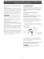
4. Provide an Adequate Gas Supply
This cooktop is designed to operate on natural gas at 4"
(10.2 cm)of manifold pressure only.
A pressure regulator is connected in series with the
manifold on tile cooktop and must remain in series with
tile supply line.
For proper operation, tile maximum inlet pressure to
the regulator must be no mere than 14" (35.6 cm) of
water column (W.C.) pressure.
For checking the regulator, the inlet pressure must be at
least 1" (2.5 cm) (or 2.5 kPa) greater than the regulator
manifold pressure setting. The regulator isset for 4"
(10.2 cm) of manifold pressure, tile inlet pressure must
be at least 5" (12.7 cm).
The gas supply line to the cooktop should be Y2"(1.3
cm) or sA" (7.9 cm) pipe.
5. LPiPropane Gas Conversion
This appliance carl be used with Natural gas or LP/
Propane gas. It is shipped from the factory for use with
natural gas.
If you wish to convert your cooktop for use with LP/
Propane gas, use the supplied fixed orifices in tile
package containing tile installation Instructions Manual,
in a bag marked "FOR LP/PROPANEGAS CONVERSION".
Follow the installation instructions packaged with tile
orifices.
The conversion must be performed by a qualified service
technician in accordance with the manufacturer's
instructions and all local codes and requirements of the
authority having jurisdiction. Failure to follow
instructions could result in serious injury or property
damage. Tile qualified agency performing this work
assumes responsibility for the conversion.
Failure to make the appropriate
conversion can result in personal injury and property
damage.
Important: Remove all packing material and
literature from cooktop before connecting gas and
electrical supply to cooktop.
5. Install Pressure Regulator
Install the pressure regulator with the arrow on the
regulator pointing up toward the unit in a position where
you can reach the access cap.
FIRE HAZARD. Do not make the
connection too tight. The regulator is die cast.
Overtightening may crack the regulator resulting in a gas
leak and possible fire or explosion.
Manual GAZFLOW Pressure
Shutoff Flare _@ Flare Regulator
Valve Union Union
On_ Flexible Connector[ _®'''"'"'_®J
Off
All connections must be wrench4ightened
Figure 8
Assemble the flexible connector from the gas supply pipe
to the pressure regulator in order: 1- manual shutoff
valve, 2- _/2" nipple, 3- _/2"flare union adapter, 4-
flexible connector, 5- _/2"flare union adapter, 6- _/2"
nipple, pressure regulator.
Use pipe-joint compound made for use with Natural and
LP/Propane gas to seal all gas connections. If flexible
connectors are used, be certain connectors are not
kinked.
The supply line should be equipped with an approved
shutoff valve. This valve should be located in the same
room as tile cooktop and should be in a location that
allows ease of opening and closing. Do not block access
to the shutoff valve. The valve is for turning on or
shutting off gas to the appliance.
To Appliance
Shutoff Valve
Figure 9
To gas supply line
Open the shutoff valve in tile gas supply line. Wait a
few minutes for gas to move through the gas line.

Checkfor leaks. Leaktestingoftheapplianceshallbe
conductedaccordingtothemanufacturer'sinstructions.
Afterconnectingthecooktoptothegassupply,check
tilesystemforleakswithamanometer.Ifa manometer
isnotavailable,turnonthegassupplyandusealiquid
leakdetector(orsoapandwater)atalljointsand
connectionstocheckforleaks.
Donotuseaflameto checkforleaks
fromgasconnections.Checkingforleakswithaflame
mayresultinafireorexplosion.
Tightena[[connectionsif necessaryto preventgas
leakageinthecooktopor supplyline.
Checkalignmentof valvesafterconnectingthe
cooktoptothegassupplytobesurethecooktop
manifoldpipehasnotbeenmoved.
Disconnectthiscooktopandits individualshutoff
valvefromtilegassupplypipingsystemduringany
pressuretestingofthatsystemattestpressuresgreater
thanY2psig(3.5kPaor14"(35.6cm)watercolumn).
Isolatethecooktopfrom thegassupplypiping
systembyclosingitsindividualmanualshutoffvalve
duringanypressuretestingoftilegassupplypiping
systemattestpressuresequaltoorlessthanY2psig
(3.5 kPa or 14" (35.6 cm) water column).
7, Connect Electricity to Gas
Cooktop
Electrical Requirements
120 volt, 60 Hertz, properly grounded branch circuit
protected by a 15 amp circuit breaker or time delay fuse.
Do not use an extension cord with this cooktop.
Grounding Instructions
IMPORTANT Please read carefully.
For personal safety, this appliance must be properly
grounded.
Tile power cord of this appliance is equipped with a 3-
prong (grounding) plug which mates with a standard 3-
prong grounding wall receptacle (see Figure 8) to
minimize the possibility of electric shock hazard from the
appliance.
Preferred Method
Grounding
type wall
receptacle Power supply cord with
3-prong grounding plug
Figure 10
Where a standard 2-prong wall receptacle is installed, it
is the personal responsibility and obligation of the
consumer to have it replaced by a properly grounded 3-
prong wall receptacle.
Do not, under any circumstances, cut or remove the
third (ground) prong from the power cord.
Disconnect electrical supply cord from
wall receptacle before servicing cooktop.
8. Check Operation
Refer to the Use and Care Guide packaged with the
cooktop for operating instructions and for care and
cleaning of your cooktop.
Do not touch the burners. They may be hot enough to
cause burns.
Install Burner Caps
This cooktop is equipped with sealed burners as
shown (see Figure 11).
T--y
Burner Base-_
Burner Pan /
Built-in) ',
\
Gas Opening
The wall receptacle and circuit should be checked by a
qualified electrician to make sure the receptacle is
properly grounded.
/
Electrode --/
Figure 11
7

A. Unpack burner bases and caps.
B. Place burner base over each gas opening tube.
C. Make sure the burner is properly aligned and
leveled. Place burner cap over each burner
base.
NOTE: There are no burner adjustments necessary on
this cooktop.
2. Turn on Electrical Power and Open Main Shutoff
Gas Vatve
Check the Igniters
Operation of electric igniters should be checked after
cooktop and supply line connectors have been
carefully checked for leaks and the cooktop has
been connected to electric power.
To operate the surface burner:
A. Push in and turn a surface burner knob to the
LITE position. You will hear a little ticking noise;
this is the sound of tile electric ignitor which
lights the burner.
B. After the burner lights, turn to the desired flame
size. The controls do not have to be set ata
particular mark. Use the marks as a guide and
adjust the flame as needed.
4_
Adjust the "LO" or "SIMMER" Setting of Surface
Burner Valves (see Figure 12)
Push in and turn each control knob to the "LO" (or
"SIMMER") setting. The "LO" setting of each
burner has been set at the factory to the lowest
setting available to provide reliable reignition of the
burner. If it does not stay lit on the"LO" setting,
check the setting asfollows.
Hollow Valve
System
A. Allow cooktop to cool to room temperature.
B. Light all burners by turning each control knob to
LITEuntil burners ignite, and then set them at
"HI".
C. _turn the knob to tile LOWEST POSITION.
D. If burner goes out, readjust valve asfollows;
Remove the surface burner control knob, insert a
thin-bladed screw driver into tile hollow valve
stem and engage the slotted screw inside.
Flame size can be increased or decreased with
the turn of the screw. Adjust flame until you
can quickly turn knob from HI to LOWEST
POSITIONwithout extinguishing the flame.
Flame should be as small as possible without
going out.
E. If you need to adjust another burner, repeat the
steps from A to D above until all burners operate
properly.
When All Hookups are Complete
Make sure all controls are left in tile OFF position.
Make sure the flow of combustion and ventilation air to
the cooktop isunobstructed.
Model and Serial Number Location
Tile serial plate is located on the underside of the
cooktop.
When ordering parts for or making inquires about your
range, always be sure to include the model and serial
numbers and a lot number or letter from tile serial plate
of your cooktop.
Your serial plate also tells you the rating of tile burners,
the type of fuel and the pressure the cooktop was
adjusted for when it left the factory.
Before You Call for Service
Read tile Avoid Service Checklist and operating
instructions in your Use and Care Guide.
Check to make sure the house fuse or circuit breaker for
your cooktop are not blown or open.
Figure 12
Page is loading ...
Page is loading ...
Page is loading ...
Page is loading ...
Page is loading ...
Page is loading ...
Page is loading ...
Page is loading ...
Page is loading ...
Page is loading ...
Page is loading ...
Page is loading ...
Page is loading ...
Page is loading ...
Page is loading ...
Page is loading ...
Page is loading ...
Page is loading ...

r,o
...4
TOP BURNER IGNITER
OPTIONAL
QUEHAOOR DE ENCEh@IDO Bb4SERl@_
OPC[ONAL
BOUOIE D'ALLUHAGE-BRULEUR
--I
i
lOP BURNER IGNITER Ff_41
OPTIONAL
O_JEMABOR C_ ENCENDIDO BUPER!OR
OPCIC_L
_DUG[E D'ALLUHAGE BRULEUR
FACULTATiF
i
1
TOP BURNER IGNITER
QUENAOOR b_ ENCENOJDO SUPERIOR
BOUGIE D'ALLUNAGE-BRULEUR
i i
I I
i i
I I
i i
i i
I I
i i
i i
i i
i i
i i
TOP BURNER IGNITER
OUEHAOOR DE ENCENOIOO SL#ER]OR
BOUGIE D'ALLUMAGE _IULEU/_
II
i i
i i
i i
i i
i i
i i
GROUND _[PUEBTA A TIERRA
M!SE A LA TERRE
i i
i I
i i
i i
I I
I I
RIGHT REAR
]GNSW.
]N_ENCTRASERO
DERECHO
INTERALLUM
OAR
LEFT REAR
ICNSW
INTENC TRASERO
IZQUIERDO
INTERALLUN
GAP
LEFT FRONT
IGNSW
INTENC DE
FRENTE IZQUiERPE)
INTER ALIUH
G AV
RIGHt FR(I_I
ICqSW
INTENC DE
FKENTE DERECHO
INTERRLLUM
DRV
CONNECTOR
ENPALME
CONNECTEUR
DIBCONNECI P0#ER BEFORE SERVICIMI UNIT
AVISO
BESCONECTE LA ENERGIA ANTES DE REALiZAR
EL NANTEN]NIENTO OEL ELECTROOOMESTICO
AVERTISSENENT
COUPER LE COURAN] AVAN] D'EFFECTUER LA
REPARATION
COL(]@ CODE / CODIC,OS DE CCLOR / CODE COULEUR
BK ELACK / NEGRO / NO}R
W WHTE / BIANCO / BLANC
}
POWER CORD
PARA TRANSPORTE
DE FUERZA
CA@E
O'ALIHENTATION
2 _8
I 80
_]RE GAGE
ALAMBRE MEO[DA
F]L CAL
200 3304
i50 3321
TEMP'C
STYLE UL
L1
CAUTION:
LA_L ALL WIRES PRIOR TO DISCBNNECTION WHEN SERVICING C@qTROLS
WIRING ERROR CAN CRUSE IMPROPER AND DANGERCLB OPERATION
VERIFY PROPER O_RATION AFTER SERVICING¸
AVISO:
ETIF_ETE TOPOS LOB ALA_REB ANTES DE OESCO_C]I_ PAR
REALIZAR ET MANTENIM]ENTO DE LOS CONTROLESEREE)R DE
ALAPBRAJE PUEDE CAUSAR UN FUNC[ONANIENTO IN_0RRECTO
Y PELIGROBOVERIObE Bi EL FUNCIONANIEN]O ESTA
CORRECTO DESPUEB DEL MANTENIMIENTO
AVERT[SSEMENT:
ETIC_ETER C]IAQUE FIL AVANT LE DEBRANCI_NENT DE CEUX CIbNE ERREUR DE
BRAN{HEMENT PEUT CAUBER UNE OPERATiCN OANGEREUE_ VERIFIER LE BO_
YOK_TIONNE_£NT D£ L'APPAREiL APREB TOUTE REPARATION¸
RIGHT FROKT LEFT FRONT
]GNSW IGNSW
]NTENC DE [NTLNC DL
FRENTE BERECHO FRENT_ IZOUi_O
]NTERALLUM INTERALLUM
DAV G_V
i-::::::
LEFT REAR RIGHT RFAR
GN B14 ION Sb
INT ENC TRA_RO INT ENC TRASERP
IZOU 1ERO0 DER_CHO
iNTER ALLUN INTER ALLUM
GAR DAR
TOP BURNER IGNITER
QUEMADOR DE ENCENDIDO BUPERIOR
BOUG[E D'ALLUNAD_ BRULEUR -_
TOP BURNER [GNI]ER
QUEHADBR DE ENCENOIDO SUPERIOR
@OUGiE D'ALLUMAGE-BRULEb_ _
O0 LC_
TOP BUR'NER IGN}TER
O_NADCR DE ENCENOIDO SUPER[OR
TOP BORER [GNI1ER
QUEMADOR DE ENCENDIOO BL@ERIOR
BOUGiE D'ALLUHAGE _ULEOR
_0 O NO
i3NITER MOON E BOARD
CUADRO BE MODULO DE ENCENDID(
BLOC CONNECTION ALL_EUR
I
318047111 REV.B

ro
co
ro_- BURNE2 ]GNI FER
Ot5 P?\DB_ ) INC 'JBI)O !,UPEI BR
BBUGiE D'ALLUMAGE 8RULEUR
3 r_
i
i
TOP BURNER iGN]TFR
QUEMADOR DE ENCEND[DO SUPERIOR
BOUGiE D'ALLUNAGE BRULEUR
TOP BURNER IGNITER
OOEMADOR DE ENCENDIDO SUPERIOR
BOUGiB B'ALLBMAGE BRULEBR
C
x 4
£
R4i
WARN NO
DISCONNECT POWER BEFORE SERV C NG UNIT
AViSO
DESCGNECTE LA ENERGIA ANTES DE REALIZAR
EL MAN1EN I M iENTG DEL iB EC IRBBGKEB_ I CO
DISCONNECT POldER BEFORE SERVICING UNIT
AVERT I SSEHENT
COUPER LE COURANT AVANT O'EFFECTUER LA
REPARAT ] ON
4 20 I /5O_C 338
18 I 20O_C 3304
3
2 /S I 20O_C 507!
18 I 150_C
/ 4 1
,_ I RE GAGE UL STYLE
ALAP'BR blED DA ]EP'P C HOBO Ut
FIL CAL B Y/E Jl
TOP BURNER IGNITER
GUEMADOR DE ENCEND!DO SUPEREOR
BOUCLE D'ALLUHAGE BRULEUR
E
TOP BURNER I GN] TEA
QUENADOR DE ENCEND I DO SUPER I DR
BOUGE D" ALLUMAGE BRULEUR
CUA[}FO ) It@}ULO ) ENC N)[BO I _5 6
BLOC CONNEC1 ON AL{ UMEUR
GROUND ?
PUEETA A TIER_A
MSE A LA TERRE
I IGHT REAR
I GN _W
]NT ENC TRASERO
DERECHO
J NTER ALLUH
DAR
R 4
I EFT REAR
IGN BW
IN] ENC iRASERO
I ZOO ] ERDO
INTER ALLUH
GAR
R 4
I EFT FRONT
[GNSW
[NTENC DE
FRENTE [ZOU[ERDO
INTER ALLUM
G AV
R
RIGIIT/:F_ONT
ION BW
INTENC DE
FRENTE DERECHO
INTERALLUH
DAV
R4
/ CENTRE REAR
IGN SW
INT ENC CENTRO
TRASERO
INTER ALLUN
CAR
CONNECTOR
EHPALHE
30NNBGTEUR
POWER CORD
PARR TRANSPORTE
DE FUERZA
CABLE
D'AL]MENTATiON
B<IBLAO< / NEGRO / NOIR
'_ I_DITE / BLANCO / BLANC
R ICED / F/BJG / ROUGE
COLOR CODE / COD]GOB DE COLOR /
CODE COUL EUR
L1
CAUT ION:
LABEL ALL WIRES PRIOR TO DISCONNECT ION bHEN SER\,iCING CONTROLS
WIRING ERROR CAN CAUSE ]MPRDPER AND DANGEROUS OPERATION
VERIFY PROPER OPERATION AFTER SERVICING
AVtSO:
ET OBE/E TOOCB lOS A.AKBRES ANES D DEBCONECTAR PAR
RLA ZAR • P'ANTLNIH ENTO DL i OS CONTROLES ERROR DE
ALAIqBRAJE PUFDE CAUSAR UN UNC[ONAMI N O INCORR C[O
Y PEL]GROSO VER]OUE S] EL _UNC ONAMIEN OESTA
CO RE( O P _Ek,lb DE] MAN NIM[EN O
AVERTtS,_EMENT:
ET[QUETER CNACUE FIL AVANT _E DEBRANCHEHENT DL CEUX CIUNE ERRLUR DE
BRANCJiEHENTI:_ELN CAUSEI:_ LiNE OPERA]ION [)ANBEREUBEVERIFiER IE DON
FDNOiONNENEN_ DE L'APPARE[L APRES TOU E REPARATiCh
CENTRE REAR RIGHT FRONT
[GNSW ]GNSW
[NT i NC CFNiRO ]N]EN8 DE
RA_RO FRENTE DERECHO
iNTERALLUM INT_RA_LUM
CAR DAV
LEFT FRCNT _EFI REAR IN@q] REAR
IGNSW [GNSW [GNSW
INT FNC DE INI ENCTRASERO iNTENCTRASERO
FRENYE IZ@LNERBO IZ_}IERBO DERECI40
]NT_RSLLUM INTERALUH INiERALLBH
GAV GAR DAR
318047112 REV.A
TOP BURNER IGNITER
OBEHAD R O ENCEND I_© S _ROR _ _ IN
BOOGIE D" ALLUMAGE BRULEUR
NO :
BRV I CE : I F EIL AC:MN O /M NAB BCOME NECEBB \RY, CC'MPAI_ABi E ,0 Jl TYDE AN[
GAGE AND COMPARABLE TERMINALS MUST BE USED
NO & :
EN CRSO CUE SEA NECESARIO DE REEb' LAZAF LOS BORNES,E5 NECESA_ O DE blrlL ZAR
EL M]SMD TPO DE ALAMBRE Y DE MEDIDOR Y EL _]ISMO TIPO DE BORNES
N[) TE :
5ER\,ICE:S DES F L5 OU DES COSSES DO[VENT E]RE REMPLACES, biT ILSEZ DES SECES
DE CALIBRE ET DE YRES EQUIVALENTS
-
 1
1
-
 2
2
-
 3
3
-
 4
4
-
 5
5
-
 6
6
-
 7
7
-
 8
8
-
 9
9
-
 10
10
-
 11
11
-
 12
12
-
 13
13
-
 14
14
-
 15
15
-
 16
16
-
 17
17
-
 18
18
-
 19
19
-
 20
20
-
 21
21
-
 22
22
-
 23
23
-
 24
24
-
 25
25
-
 26
26
-
 27
27
-
 28
28


Ask a question and I''ll find the answer in the document
Finding information in a document is now easier with AI
in other languages
Related papers
-
Frigidaire FGC30S4ASC Installation guide
-
 Kenmore Elite FPGC3077RSC Installation guide
-
Frigidaire GLGC36S8EQA Installation guide
-
-
Frigidaire FFGC3025LB Installation guide
-
Frigidaire FGGC3665KS Installation guide
-
Frigidaire FGGC3045QW Operating instructions
-
Frigidaire FGGC3045QS Installation guide
-
Frigidaire FFGC3015LSC Installation guide
-

Other documents
-
Kenmore 79032413900 Installation guide
-
-
Kenmore Elite 79033223401 Installation guide
-
-
Kenmore Elite 36'' Sealed Gas Cooktop 3243 Installation guide
-
 Kenmore Elite 79032353001 Installation guide
-
-
 Frigidaire Professional 1227104 Installation guide
-
GE JGP628SEJ1SS Installation guide
-
Whirlpool 9761893 Installation guide

