Page is loading ...


Introduction
The RL D 10 makes pinpointing leaks as easy as one, two! Detect leaking
r e f r i g e r ant using the high sensitivity mode then switch to the low sensitivity
mode to pinpoint its source. If background noise makes the audible tic
hard to hear, you can count on the color scaled LED indicators.
Features include
• Auto zeros when turned on
• LED panel indicates refrigerant leak concentration
• Two position sensitivity selector
• Audible tick rate
• Long Gooseneck probe
• One-hand operation
• Automatically detects all existing refrigerant and blends
Safety Notes
Before using this instrument, read all safety information carefully. In
this manual the word "WARNING" is used to indicate conditions
or actions that may pose physical hazards to the user. The word
"CAUTION" is used to indicate conditions or actions that may
damage this instrument.
NOTE: This instrument intended for use by professionals who know the
h a z a r ds associated with their trade. Ac c o r d i n gly, this manual is oriented
t o w a r d gas leak detection, not re f r i ge rant system maintenance.
Some of the latest refrigerant systems use combustible gasses in place
of halogen based gasses. We recommend that you also obtain a quality
combustible gas leak detector, such as UEi’s CD100A to determine and
detect gas leaks when working with unknown substances.
WARNING!
Turn this instrument off before cleaning or replacing the sensor.
Failure to do so may result in a mild electrical shock.
International Symbols
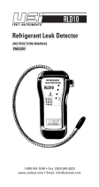
C o n t r ols and Indicators
1. Sensor tip guard
2. S e n s o r
3. Gooseneck probe
4. Earphone jack
5. Rubber boot
6. L ED gas concentration indica t o r s
7. Amplified audio gas concentration indica t o r
8. Pow e r - o n - i n d i cator and low battery indica t o r
9. Power/mode slide switch
Operating Instructions
Functional Description
The RLD10 runs through a brief warm-up and self-calibration when it is
initially turned on. Typically, you can observe the following sequence of
events when the unit is turned on in fresh air:
1. The power-on indicator light glows steadily green*.
2. A single audible tic is heard.
3. The panel of light emmiting diodes (LED’s) turn on and off in
sequence; green, yellow, light red, dark red (from bottom to top).
4. The bottom LED (green) flashes for about two seconds.
5. All LED’s except the power-on indicator turn off for approximately
three seconds.
6. At approximately three second intervals an audible tic sounds and
the lowest LED flashes.
RLD10-MAN P. 1
1
2
3
4
5
7
6
9
8

M a i n t e n a n c e
Periodic Service
WARNING!
Repair and service of this instrument is to be performed by qualified
personnel only. Improper repair or service could result in physical
degradation of the instrument. This could alter the protection from
electrical shock and personal injury this instrument provides to the
operator. Perform only those maintenance tasks that you are
qualified to do.
These guidelines will help you attain long and reliable service from
your instrument:
• Calibrate your instrument annually to ensure it meets original
performance specifications
• Keep your instrument dry. If it gets wet, wipe dry immediately.
Liquids can degrade electronic circuits
• Whenever practical, keep the instrument away from dust and
dirt that can cause premature wear
• Although your instrument is built to withstand the rigors of daily
use, it can be damaged by severe impacts. Use reasonable
caution when using and storing the instrument
Cleaning
Periodically clean your instruments case using a damp cloth. DO NOT
use abrasive, flammable liquids, cleaning solvents, or strong detergents
as they may damage the finish, impair safety, or affect the reliability of
the structural components.
NOTE: Ce r tain soaps may be detected by the RL D 10. Check for sensitivity
b e f o r e using any soap, and re m o ve as much of the residual as possible
with a damp cloth.
Do not allow moisture to directly contact the speaker just inside the face
of the instrument, or enter the instrument’s housing. Remove the sensor
tip gu a rd prior to cleaning it. Rinse and dry this component thoro u gh l y
b e f o r e re p l a c i n g .
Cleaning and Replacing the Sensor
Although the sensor is designed to offer many years of reliable service,
it may become inoperable if it becomes corroded or is otherwise
physically damaged.
You can clean the sensor, once i
t is disassembled, using denatured alcohol
on the tip assembly and a bottlebrush on the metal tip housing.
*If the power-on indicator is a pinkish-red, the battery is becoming weak
and should be replaced immediately. A low battery will adversely affect
the instrument’s reliability.
Each time the instrument is put into service, you can conduct a quick
functional test. Simply allow the instrument to run through its
self-calibration sequence in fresh air, then expose the sensor to an
uncapped permanent marker (highlighters will not work). The audio
and visual indicators respond as they would if they found a small leak.
Be careful not to touch the marker to the tip, or you will get a false
indication until the ink dries.
Modes of Operation
Your RL D 10 can operate in either high sensitivity or low sensitivity mode.
Begin using your RLD10 with the power/mode slide switch in its
uppermost position. This is the instrument’s most sensitive position.
Move the tip along suspect tubing, seals and fittings at a rate of
approximately 1/2” to 1” per second. When the sensor in the probe tip
detects a refrigerant gas, the tic rate will increase and a corresponding
LED indicator will begin to increase and a higher positioned LED flashes.
To pinpoint the leak, change the power/mode slide switch position
from the uppermost position to the center position. This will decrease
sensitivity, allowing you to get closer to the source of the leak before
a maximum concentration is indicated.
If the situation calls for quiet operation, or if background noise makes it
difficult to hear the built-in speaker, you can use an earphone. The jack
is on the side of the instrument. Note that listening to the earphone is
very loud. Your LED indicators will continue to function as normal.
The LED Indicators
There are four LED indicators along the right side of the instrument.
These indicate the relative concentration of gas detected, and directly
correspond to the tic rate.
When no gas is detected, the LED panel will flash a single green LED
corresponding to the occasional tic. As the sensor moves closer to
the source of a gas leak, the LED that corresponds to the relative gas
concentration will flash each time there is an audible tic. From bottom
to top, the LED’s are green, yellow, light red, and dark red.
RLD10-MAN P. 2
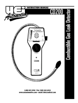
Tip guard
Metal tip housing
Sensor tip
White plastic
base contact
Gooseneck

Disassembly of Sensor
1. Turn the instrument’s power off. Mild electrical shock may result if
you make contact with the sensor while power is on.
2. Remove the tip guard from the metal tip housing by twisting it
clockwise while away from the Gooseneck.
3. Remove the metal tip housing from the Gooseneck by holding the
Gooseneck steady while turning the tip housing counterclockwise.
• The base contact assembly may adhere to the tip housing as it
comes out. If so, the tip housing will tend to spring-back
clockwise with every counterclockwise turn.
• Continue turning as described until the metal housing can be
lifted away from the wand. You may have to hold it in place
after each turn.
• Pull the housing up just far enough to view the insulation on the
white plastic base contact.
• Grip the exposed white insulation with needle-nosed pliers,
holding it firm with the Gooseneck.
• Separate the metal housing away from the Gooseneck.
4. The sensor tip will commonly remain in the metal housing, and
must be forced out from the top (toward the Gooseneck end) with
a toothpick or similar instrument.
Replace or clean the sensor as desired then reassemble in reverse order.
Proper function depends on the unit’s electrical contacts. Make sure the
tip assembly is making good contact with the base and there is good
metal-to-metal contact on the tip housing-to-Gooseneck connection.
Calibration
When properly maintained, your instrument is sensitive to refrigerant
leaks as small as .4 ounces per year. To ensure your instrument is
performing at its peak, send it to the UEi factory or a qualified
instrument calibration facility for annual certification.
Battery Replacement
Always use a fresh replacement battery of the specified size and type.
Immediately remove the old or weak battery from the meter and
dispose of it in accordance with your local disposal regulations. Batteries
can leak chemicals that corrode electronic circuits. If your meter is not
going to be used for a month or more, remove
and store the battery in
a place that will not allow leakage to damage other materials.
Replace battery when:
• The green “READY” light begins to glow red
• No lights or other activity occurs upon turning the instrument on
• Tic rate quickly begins to increase when no refrigerant is
being detected*
*An increase in tic rate may be experienced if the unit remains on for a
long period. This is a normal response to decreasing battery life. Turn
the unit off and allow it to recalibrate in fresh air if this occurs.
To install a new battery, follow these procedures:
1. Remove the battery cover.
2. Remove the battery using a coin or screwdriver.
3. Replace the battery, observing indicated polarity.
Tro u b l e s h o o t i n g
This unit contains no user serviceable parts beyond those listed in the
table. In the event your instrument is physically damaged or does not
function properly after taking the listed action, please return the
instrument to UEi following the warranty and service instructions.
S p e c i f i c a t i o n s
Operating Conditions
To ensure accurate readings from your RLD10, use it only when ambient
air is within this range:
Temperature: 32 to 120˚F
Humidity: 0 to 80% RH (non condensing)
Gasses Detected
The RLD10 detects a wide variety of refrigerant. The following list
represents a portion of the refrigerant and gasses detected:
R11 R12 R13 R22
R23 R113 R114 R134A
R500 R502 Halons R404A
SF6 Perchlorethylene Blends R410A
RLD10-MAN P. 3
If I See This
Malfunction
Instrument does not
turn on
Instrument does not tic
after it is switched on,
but the lights work
Appropriate indicators
do not light
The tic rate does not
increase when the sen-
sor is exposed to
refrigerant or other
detectable gas
Tic rate increases
during use
Tic rate remains fast
after warm up
The green power-on
indicator appears red
I Should
Check For
Battery voltage
Mode switch position
Earphone jack
Battery voltage
Airflow to sensor
Sensor connection
Sensor contamination
Reduced battery voltage
Moisture in sensor cavity
Moisture in sensor cavity
Battery voltage
Battery voltage
Then Take This Corrective
Action
Replace low battery
Place firmly in Low or
High position
Remove earphone plug or
debris inserted in receptacle
Replace low battery
Clear restriction
Clean and tighten sensor
component contacts
Clean or replace sensor
Cycle off (5 seconds) and
back on (Recalibrates to
compensate for
decreasing voltage)
Disassemble and dry sensor
Disassemble and dry sensor
Replace low battery
Replace low battery

Physical Characteristics
Functional Characteristics
RLD10-MAN P. 4
Size: Height by Width by Depth
(with probe wrapped around boot)
Probe length: fully extended
Weight (battery installed)
8” x 4” x 1 1/2”
18 1/2” (47cm)
14.1 Oz (400g)
Power requirements
Average battery life (Continuos use)
Leak detection sensitivity
Sensor
Duty cycle
Typical response time
Warm up period
Sensor output (voltage/current)
Visual level indicators
One 9 volt alkaline battery
Approximately 8 hours
.4 Oz/year (11 grams/year) R134A
using LS20 leak standard
Corona discharge
Continuos
Less than 1 second
(allows for 1”/sec seek rate)
10 second average
A. No -load high voltage: 2500V ±10%
B. Current: 24 mA
C. Loaded high voltage: 2400V ±50V
(loaded with 100.0 M Ohms
Four tic-rate scaled LED indicators
changing from green to yellow to light
red to red (indicating relative,
not specific quantities)

Limited Warranty
The RL D 10 is warranted to be free from defects in materials and workmanship for a period of
one year from the date of purchase. If within the warra n ty period your instrument should
become inoperative from such defects, the unit will be repaired or replaced at UEi’s option.
This warra n ty covers normal use and does not cover damage which occurs in shipment or
failure which results from alteration, tampering, accident, misuse, abuse, neglect or improper
maintenance. Batteries and consequential damage resulting from failed batteries are not
covered by warra n ty.
Any implied warranties, including but not limited to implied warranties of merchantability
and fitness for a particular purpose, are limited to the express warranty. UEi shall not be
liable for loss of use of the instrument or other incidental or consequential damages,
expenses, or economic loss, or for any claim or claims for such damage, expenses or
economic loss. A purchase receipt or other proof of o
riginal purchase date will be required
before war
ra n ty repairs will be rendered. Instruments out of warra n ty will be repaired (when
r e p a i r able) for a service charge. Return the unit postage paid and insured to:
This warranty gives you specific legal rights. You may also have other rights which vary from
state to state.
RLD10
Refrigerant Leak Detector
Copyright © 2007 UEi RLD10-MAN 1/07
PLEASE
RECYCLE
99 Washington Street
Melrose, MA 02176
Phone 781-665-1400
Toll Free 1-800-517-8431
Visit us at www.TestEquipmentDepot.com
/