Page is loading ...

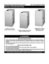
Installation Instructions
!
WARNING!
To avoid the risk of electrical shock, personal injury,
or death, disconnect electrical power before install-
ing this kit or performing maintenance.
Before beginning installation, read these instructions thor-
oughly and follow all warning and cautions in these instruc-
tions and on the unit. These instructions are primarily
intended to assist qualified individuals experienced in the
proper installation of this appliance. Some local codes
require licensed installation/ service personnel for this type
of equipment. Improper installation, service, adjustment,
or maintenance can cause fire, electrical shock or other
conditions which may result in personal injury or property
damage. Unless otherwise noted in the instructions, only
factory authorized kits or accessories may be used when
modifying this product.
1. SPECIFICATIONS
The variable speed blower kit is designed for installation in
gas furnaces, “B” and “C” cabinet models only. This kit is
not applicable for “A” cabinet models. This kit may be field-
configured for air conditioning/heat pump airflows from 2 to
5 tons nominal capacity.
2. INSTALLATION REQUIREMENTS
Check Equipment - After unpacking, inspect the kit thor-
oughly for concealed damage. If damage is found, notify
the transportation company immediately and file a con-
cealed damage claim. All installations shall be made as
described in the installation instructions and in accordance
with applicable national and local codes including the
requirements of local utilities.
3. INSTALLATION
Upflow Installations
1. Disconnect electrical power to the furnace.
2. Remove the upper and lower access doors from the
furnace.
3. Remove the electrical plug containing the blower wires
from the receptacle located on the left side of the
blower deck.
4. Remove the blower assembly from the furnace.
Variable Speed Blower Kit for Gas Furnace Applications
5. Attach the blower mounting brackets to the variable
speed blower. The brackets may be included with the
kit or may be taken from the old blower.
6. Slide the variable speed blower kit into the furnace. Be
sure that the sides of the blower are captured by all of
the blower mounting tabs in the blower deck. Secure
with the two screws removed in step 4.
7. Remove the plastic cap from the extra hole in the
blower deck located on the left side.
8. Route the bundle of wires coming from the control box
of the kit through the extra hole in the blower deck.
Secure the wires through the hole using the strain relief
bushing provided.
9. Skip to section marked “All Applications”.
Downflow Installations
For downflow installations, the blower control box will be
mounted separately from the blower. Begin installation by
preparing the blower as follows.
1. Remove the blower control panel from the blower
leaving all wiring connected.
2. Attach included mounting feet to the control box.
Mount so that the mounting flanges are parallel to the
control box and facing out.
80+ Downflow
1. Disconnect electrical power to the furnace
2. Remove the upper and lower access doors.
3. Remove the blower motor leads from the control board.
4. Remove the flue pipe from in front of the blower access
door.
5. Remove the blower access door.
6. Slide the entire blower assembly out of the furnace.
7. Install the variable speed blower into the furnace with
the motor on the left side. Be sure that the sides of the
blower are captured by the blower mounting tabs in the
blower deck.
8. Re-install the blower access door and carefully route
the blower wiring through the strain-relief bushing on
the left side.
9. Mount the blower control box onto the blower access
door. If the unit does not have holes provided, add
1/8” holes per Fig. 1.
10. Skip to section marked “All Installations”.

2
90+ Downflow
1. Disconnect electrical power to the furnace.
2. Remove the upper and lower access doors.
3. Remove the blower motor leads from the control board.
4. Remove the flue pipe and combustion air intake where
it is in front of the blower access door.
5. With other wiring still intact, remove the blower access
door and carefully place aside, being careful not to
damage the components or wiring.
6. Slide the entire blower assembly out of the furnace.
7. Install the variable speed blower into the furnace with
the motor on the left side. Be sure that the sides of the
blower are captured by the blower mounting tabs in the
blower deck.
8. Re-install the blower access door and carefully route
the blower wiring through the strain-relief bushing on
the left side.
9. Mount the blower control box onto the blower access
door. If the unit does not have holes provided, add
1/8” holes per Fig. 1. Also, if mounting holes are not
Figure 1. Downflow Blower Access Door
3-1/8"
4-1/4"
2"
13-7/8"
5"1"
4-1/4"
1/2"
1"
1-1/4"
2"
RK RL
RK RL
On *RL & *RK
models, add 4 mounting
holes for control box.
On *RL models,
relocate the pressure
switch here.
On *RL models, re-
locate the transformer
down 1/2" and over 1"
Figure 2. Wiring Diagram
R
C
Y
G
W
Gas Valve
Motor Plugs
Neutrals
Connect the white wire
from the motor box to
one of the unused
neutrals on the furnace
control board.
YELLOW
YELLOW
GREY
RED
GREEN
WHITE
W
W
RED
R
R
131175
1234567
Remove L1 transformer
lead and replace it with
L1 lead from kit. Connect
transformer L1 to "piggy-
back" spade provided on
L1 lead from kit.
To Transformer
GREY
YELLOW
BLUE
BROWN
ORANGE
1
2
3
4
5
6
7
8
9
10
11
12
13
14
15
16
1
2
3
4
5
L1
L1
Connect the red,
green, grey, blue, and
the short yellow wires
to the t-stat strip on
the furnace control
board. For two stage
cooling, see Insert A.
YELLOW
BLUE
1
2
3
4
5
6
7
8
9
10
11
12
13
14
15
16
Y2
Y1
THERMOSTAT
INSERT A: TWO STAGE CONDENSING UNIT
Y2
Y1
YELLOW
Y1
BLUE
Y2
CONDENSING
UNIT
REMOVE BLUE
WIRE FROM
Y TERMINAL
OF
FURNACE
BOARD

3
tions and system configurations. Before operation, the
variable speed blower kit must be configured to match the
unit with the system, system options, and climatic condi-
tions. With the variable speed blower kit installed and
configured properly, the furnace will respond directly to
thermostat inputs. During normal operation, the motor will
gradually change speed in response to changes in system
variables such as the thermostat settings, duct static,
filter, etc. The variable speed blower kit is configured by
setting the 7 switches located on the motor control board
as described below.
!
IMPORTANT!
The variable speed blower kit has been designed to
give the installer maximum flexibility to optimize
system performance, efficiency, and comfort. Be-
cause there are so many ways to configure the kit it
is important to read and follow these instructions
carefully.
Determining Nominal System Capacity
(A/C & H/P)
In order to select the appropriate airflow for AC and HP
operation the nominal system capacity must be known.
The nominal system capacity is ALWAYS the nominal
capacity of the outdoor unit. In some cases the nominal
system capacity is not the same as the nominal capacity
of the indoor coil.
Selecting The Cooling/Heat Pump Airflow
The cooling/heat pump airflow is selected by setting
switches 1 through 4 on the motor control board located in
the blower control panel. All airflows for other modes of
operation (except gas heat) are determined by this setting.
Table 1 shows the airflow values versus the airflow selector
switch settings, and the range of airflow settings recom-
mended for each nominal system capacity.
NOTE: The CFM values listed in the tables are not
dependent on duct static pressure. The motor auto-
matically compensates for changes in duct static pres-
sure (within the limits of the motor).
NOTE: For single stage cooling, the indoor blower will
operate at the CFM called out in the "High" column of
Table 1.
For maximum capacity and energy efficiency, generally, a
selection at or near the top of the CFM range for that
nominal capacity is best. For maximum dehumidification,
select an airflow near the middle or bottom of the CFM
range for that nominal capacity.
included in the furnace, the transformer and the pres-
sure switch will have to be re-located:
a. Remove the transformer.
b. Drill new 1/8” mounting holes per Fig. 1.
c. Re-install the transformer using the new mounting
holes.
d. Remove the pressure switch and pressure switch
tubing.
e. Drill new 1/8” mounting holes per Fig. 1.
f. Re-install the pressure switch using the new mounting
holes and connect using the supplied tubing.
All Installations
1. Connect wires to the furnace according to the wiring
diagram, Fig. 2. Use the “Y” adapter supplied in the
literature pouch to connect the long yellow wire to the
gas valve. Connect the remaining wires for power
supply and thermostat interface according to Fig. 2.
When connecting with a two-stage condensing unit, refer-
ence Insert A on Figure 2.
!
IMPORTANT!
On downflow 80% installations, wires must be routed
away from hot surfaces.
NOTE: The wires coming from the bottom of the
variable speed blower control box are connected to the
blower motor at the factory. Check these connections
and tighten as necessary
2. Remove the cover of the variable speed blower control
box. Refer to section 4 and configure the blower.
NOTE: Changes to blower configuration must be
made with the power to the unit OFF. Changes
made with power ON may be ignored by the blower.
3. Re-install the variable speed blower control box cover
and the furnace access panels.
4. Restore power to the furnace. Installation is now
complete.
4. CONFIGURING THE BLOWER
The variable speed blower kit is equipped with a micropro-
cessor-controlled variable speed motor that is pre-pro-
grammed to deliver optimum airflow in a variety of condi-

O'Fallon, MO
7082810 (Replaces 7082310)
Specifications and illustrations subject to change
without notice and without incurring obligations.
Printed in U.S.A. (06/03)
NOTE: If coil icing is observed, the cooling/heat pump
airflow selected may be too low. Double-check to be
sure the setting selected is within the range shown in
Table 1. Also check to be sure the system is properly
charged (see outdoor unit Installation Instructions). If
icing continues to occur, raise the selected airflow one
or two steps.
Selecting The (Gas) Heating Airflow
The heating airflow is selected by setting switches 5, 6, and
7. Refer to Table 2 and select a nominal rise based on the
furnace nominal efficiency and input. Follow the table
column up to find the switch setting and nominal air-flow.
Be sure that the selected rise is within the specification of
the furnace as shown on the furnace rating label.
5. SYSTEM OPERATION
Cooling or Heat Pump Mode
When the thermostat calls for cooling or heat pump heating
the circuit between R, G, and Y (O is ignored by the blower)
¢708281*¤
7082810
Table 2. Heating Airflow Settings
Table 1. All Cooling/Heat Pump Airflow Settings
Note: O = Off 1 = On
Nominal A/C and HP
LOW HIGH 1 2 3 4
567
Capacity
500 720 0 0 0 1
550 800 0 0 0 0
610 880 0 0 1 0
650 945 1 0 0 1
720 1050 1 0 0 0
800 1155 1 0 1 0
900 1305 0 1 0 1
1000 1450 0 1 0 0
1060 1530 1 1 0 1
1100 1595 0 1 1 0
1170 1700 1 1 0 0
1290 1870 1 1 1 0
CFM SWITCH NUMBER
2 TON
3.5 TON
4 TON
5 TON
3 TON
2.5 TON
720 900 1056 1200 1350 1500 1656 1800
7
1
0
1
0
1
0
1
0
6
0
0
0
0
1
1
1
1
5
0
0
1
1
0
0
1
1
72,000 59
51
44
90,000 63
55
49 44
96,000 67 59
53
47
108,000 67
59
53 48
120,000 66
59
54 49
126,000 69 62
56
51
144,000 71
64
59
80,000 67
59
52 47
100,000 73 65
59
53 49
120,000 71
64
59
Temperature Rise °F (Recommended settings are
Bold
)
Nominal Air-Flo
w
80+% 92+%
Switches
NOTE: 0 = OFF 1 = ON
is completed and the blower begins a pre-programmed on-
cycle “profile”. First, the blower ramps up to approximately
1/3 of the selected airflow and stays there for 30 seconds.
Next, the blower ramps to approximately 3/4 of the selected
airflow and stays there for another 30 seconds. The blower
then ramps up to the selected airflow until the thermostat
is satisfied. A one-minute off-cycle delay at approximately
1/2 of the selected airflow is initiated when the call from the
thermostat ends.
IMPORTANT NOTE: When installing a 2-stage heat
pump and a fossil fuel kit, the transformer MUST be
upgraded to one with a 60VA rating (P/N 904077).
(Gas) Heating Mode
When the thermostat calls for heating the circuit between
R and W is completed. The furnace control board initiates
the ignition sequence. When the gas valve is energized a
signal is transmitted to the blower through the wiring added
in the blower installation procedure. The blower will start
and run at a very low speed. After 30 seconds, the blower
ramps up to the selected heating airflow. The blower will
operate two minutes after the call for heating is removed.
NOTE: Off-cycle delay settings on the furnace control
board no longer control off-cycle blower timing. The off-
cycle blower timing is preprogrammed into the variable
speed blower and is not adjustable.
Manual Fan
When the manual fan switch on the thermostat is on,
energizing G only, the blower will ramp to 50% of the
selected cooling/heat pump airflow.
/