Simplex CCS0075 Hydraulic Chain Cutter - TD182_b User manual
- Type
- User manual

Instruction Manual
www.tksimplex.com Hydraulic Chain Cutter – CCS0075
2 www.tksimplex.com
INDEX
1. SAFETY REQUIREMENTS ........................................................................ 2
2. TECHNICAL DATA ..................................................................................... 3
3. OPERATION ................................................................................................. 4
4. MAINTENANCE........................................................................................... 4
5. ADDITIONAL INFORMATION ................................................................. 4
6. ASSEMBLY DIAGRAMS AND PARTS LISTS .......................................... 5
1. SAFETY REQUIREMENTS
GENERAL CONSIDERATIONS
The SIMPLEX hydraulic cutters have been designed in accordance with our quality standards and ISO 9001 rules.
The tool is designed only for the operations described in this manual. The manufacturer is not responsible for any damage caused
by incorrect operation of the tool.
SAFETY PRINCIPLES
1. This manual must be always available to the operator and all safety and operational instructions must be followed.
2. The operator should be trained about the machine operation and the corresponding safety rules regarding prevention of
accidents and protection of the environment.
3. The operator must wear personal protective equipment like helmet, glasses, gloves, boots, protective clothing, etc.
Helmet Glasses Gloves Boots Protective Clothing
4. The operator must be trained in the use and safe operation of the pump being used with the cutter. If a powered pump
(electric, air, engine driven, etc.) is being used, all personnel must be aware that the that the blade will advance
immediately when the system is pressurized and hydraulic flow is directed to the cutter.
5. All personnel must keep fingers, hands and other body parts away from the cutter blade to prevent serious personal injury.
6. Do not modify the tool in any way.
7. Follow suggested maintenance operations periodically as recommended in this manual.
8. All repairs should be performed by a qualified technician with genuine SIMPLEX parts. For further information, contact
your nearest SIMPLEX authorized service center.
9. After operation, the tool should be cleaned and stored in a clean, dry and secure location.
GENERAL SAFETY INSTRUCTIONS
Before operation, make sure the operator is on solid footing in a well-lit area.
The cutter must be used in accordance with the relevant instructions described in the manual. The user must be
aware of the inherent risks when handling high pressure hydraulic devices and ensure that a safe working
environment and safe systems of work are in place before operating the equipment.
Before use, visually inspect the tool and accessories for any damage. If any damage is found, do not use the tool until
repaired. Ensure that all the components of the hydraulic system can support the maximum pressure.

Instruction Manual
www.tksimplex.com Hydraulic Chain Cutter – CCS0075
3 www.tksimplex.com
• Perform maintenance operations with all pressure relieved (0 psi/bar).
• Do not exceed equipment ratings. Use gauges or appropriate indicator devices to be aware of the working pressure.
• After operation, clean the tool and store it in a clean, dry and secure location.
• When using a powered pump, make sure that the valve is set to the neutral position before connecting the tool.
• Ensure that the pump reservoir is full. Always check oil level with cutter blade fully retracted.
• Ensure that heavy or sharp objects are positioned away from the hoses.
2. TECHNICAL DATA
GENERAL SPECIFICATIONS
Specification
Model CCS0075
Imperial
Metric
Push capacity
(@10150 psi or 700 bar)
15.2 Ton
135 kN
Length*
11.4 in
290 mm
Height*
3.2 in
82 mm
Width*
2.6 in
67 mm
Maximum Jaw Opening*
20 in
0.8 mm
Weight
10.6 lb
4.8 Kg
* Due to rounding, the dimensions listed in this chart may be slightly different than the dimensions
shown in the diagrams in Section 6.
CUTTING CAPACITIES
Bar
Diameter*
Tensile Strength
in
mm
ksi
MPa
0.75
19
102
700
0.59
15
145
1000
0.51
13
203
1400
0.43
11
232
1600
*Maximum diameter bar that can be cut at the different tensile strengths.
Chain
Diameter*
Grades
in
mm
0.75
19
28-43
0.55
14
60-80
*Maximum diameter chain that can be cut at the different chain grades.
Manufacturer’s rating is the maximum allowable limit. Good practice encourages using the tool below
the manufacturer’s rating.
Keep the tool away from flames and heat, such as during welding.

Instruction Manual
www.tksimplex.com Hydraulic Chain Cutter – CCS0075
4 www.tksimplex.com
3. OPERATION
1. Assemble the complete system, and make sure the connection between pump, hose, coupler and tool is leak free and
correct.
2. On vented pumps, be sure that vent/fill cap (if equipped) is in the “VENT” position to allow proper pump functioning.
3. Close the pump release valve.
4. Remove the air trapped in the hydraulic circuit by operating the pump and fully advancing and retracting the cutter blade
several times. Open the pump release valve to retract the blade.
5. Insert the chain to be cut in the gap between the fixed and movable blades (max. 0.75 inch or 19 mm).
6. Close the pump release valve. Operate the pump until the blade moves forward and the chain is cut.
7. After cutting is completed, retract the blade back by opening the pump release valve.
8. Remove any traces of chain material before making another cut.
4. MAINTENANCE
REPLACEMENT OF BLADES
Note: Refer to Section 6 of this manual for parts list and item numbers. To help prevent damage to the tool, always
perform blade replacement procedures in a clean and dry work area.
To prevent possible serious injury, always relieve hydraulic pressure (0 psi/bar) and disconnect hydraulic hose
from tool before beginning blade replacement procedures.
A. FIXED BLADE:
1. Loosen and remove the stud (7).
2. Push the old blade (6) out using a nail inserted through the hole in the cutting head. Remove the old blade (6).
3. Apply Loctite 242 to the threads of the stud (7).
4. Insert a new blade (6). Then, reinstall and tighten the stud (7) to secure the blade.
B. MOVABLE BLADE:
1. Loosen and remove the studs (7), on both sides of the piston (15).
2. Loosen the stud (17).
3. Firmly grasp the cutting head (4). Unscrew the cutter body (2) from the cutting head.
4. Loosen and remove the screw (8). Remove the old blade (5).
5. Mount a new blade (5).
6. Apply Loctite 242 thread sealant to the threads of the screw (8). Then, reinstall and tighten the screw (8) to secure the
blade.
7. Thread the cutter body (2) fully into the cutting head (4). Tighten the stud (17).
8. Apply Loctite 242 thread sealant to the threads of the studs (7). Then, reinstall the studs on both sides of the piston (15).
9. Adjust the clearance between the piston (15) and the studs (7).
Note: The studs (7) act as a piston guide. Turn each stud in or out as needed to adjust the clearance. There must be
sufficient clearance to allow the piston (15) to slide freely, but with a minimal amount of lateral movement. Clearance
should be even on both sides of the piston.
5. ADDITIONAL INFORMATION
All information, illustrations and specifications in this operation manual are based on the latest information available at the time of
publication. The right is reserved to make changes at any time without notice.
Equipment operators and installers shall be responsible for ensuring that a safe working environment and safe systems of work are
in place before operating the equipment.
Simplex declares that this product has been tested and conforms to applicable standards and complies with all CE requirements.

Instruction Manual
www.tksimplex.com Hydraulic Chain Cutter – CCS0075
5 www.tksimplex.com
6. ASSEMBLY DIAGRAMS AND PARTS LISTS
68.00
[2.7]
81.50
[3.2]
19.5
[.8]
18.9
[.7]
Ø 50.00
[2.0]
Ø 60.00
[2.4]
13.50
±
2.00
[
.53
±
.07
]
40.00
[1.6]
1911326
5
14
317
4
15
16
4
22
24
4
A
A
SECTION B-B
DECAL #DD2589226 TO BE APPLIED HERE
SEE ABOVE VIEW FOR LOCATION AND ORIENTATION.
54.00
[2.1]
67.00
[2.6]
290.0
[11.4]
9
10
20
18
12
7
11
8

Instruction Manual
www.tksimplex.com Hydraulic Chain Cutter – CCS0075
6 www.tksimplex.com
ITEM NUMBER
DESCRIPTION
QTY
*1
COLLAR ∅40 x ∅50 x 7.5
1
2
BODY
1
*3
O-RING ∅60.04 x 1.78
1
4
CUTTING HEAD
1
**5
MOVABLE BLADE
1
**6
FIXED BLADE
1
7
ALLEN STUD M12 x 16 DIN 913
3
8
ALLEN SCREW M6 x 25 DIN 912 12.9
1
9
ALLEN SCREW M8 x 30 DIN 912 12.9
1
*10
COPPER WASHER
1
11
SPRING TIE
1
12
ALLEN SCREW M8 x 16 WITH HOLE ∅3.5
1
*13
GUIDE RING ∅50 x ∅45 x 9.7
1
*14
O-RING ∅37.69 x 3.53
1
15
PISTON
1
16
RETURN SPRING
1
17
ALLEN STUD M4 x 5
1
18
SPRING TIE
1
19
FEMALE BALL QUICK COUPLER 3/8 NPT
1
*20
SEGMENT
1
22
SIMPLEX DECAL #88186
2
24
SIMPLEX DECAL #DD2589226
1
* Included in service kit CCS1125K.
** Included in blade kit CC1125BK.

Instruction Manual
www.tksimplex.com Hydraulic Chain Cutter – CCS0075
7 www.tksimplex.com

-
 1
1
-
 2
2
-
 3
3
-
 4
4
-
 5
5
-
 6
6
-
 7
7
-
 8
8
Simplex CCS0075 Hydraulic Chain Cutter - TD182_b User manual
- Type
- User manual
Ask a question and I''ll find the answer in the document
Finding information in a document is now easier with AI
Related papers
-
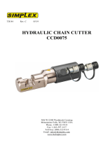 Simplex CCD0075 Hydraulic Chain Cutter - TD184_c User manual
-
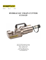 Simplex CCS1125 Hydraulic Chain Cutter - TD183_c User manual
-
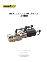 Simplex CCD1125 Hydraulic Chain Cutter - TD185_b User manual
-
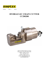 Simplex CCD0200 Hydraulic Chain Cutter - TD186_c User manual
-
 Simplex HCCS3500 Hydraulic Cable Cutter - TD194_c User manual
-
 Simplex CCP0075 Hydraulic Chain Cutter - TD181_a User manual
-
 Simplex HCCS1500 Hydraulic Cable Cutter - TD191_b User manual
-
 Simplex HCCS2375 Hydraulic Cable Cutter - TD192_c User manual
-
 Simplex HCCD2375 Hydraulic Cable Cutter - TD196_b User manual
-
Simplex HCCS3000 Hydraulic Cable Cutter - TD193_c User manual


