Wacker Neuson PS22203 User manual

Category
Water pumps
Type
User manual
5000184964 05 1111
5000184964
Operator’s Manual
Pump
PS, 3-Phase
EN
Copyright notice
© Copyright 2011 by Wacker Neuson Production Americas LLC
All rights, including copying and distribution rights, are reserved.
This publication may be photocopied by the original purchaser of the
machine. Any other type of reproduction is prohibited without express
written permission from Wacker Neuson Production Americas LLC.
Any type of reproduction or distribution not authorized by Wacker
Neuson Production Americas LLC represents an infringement of valid
copyrights. Violators will be prosecuted.
Trademarks
All trademarks referenced in this manual are the property of their
respective owners.
Manufacturer
Wacker Neuson Production Americas LLC
N92W15000 Anthony Avenue
Menomonee Falls, WI 53051 U.S.A.
Tel: (262) 255-0500 · Fax: (262) 255-0550 · Tel: (800) 770-0957
www.wackerneuson.com
Original instructions
This Operator’s Manual presents the original instructions. The original
language of this Operator’s Manual is American English.
wc_tx001370gb.fm
3
PS 3-Phase Series Foreword
Foreword
SAVE THESE INSTRUCTIONS—This manual contains important instructions for
the machine models below. These instructions have been written expressly by
Wacker Neuson Production Americas LLC and must be followed during installation,
operation, and maintenance of the machines.
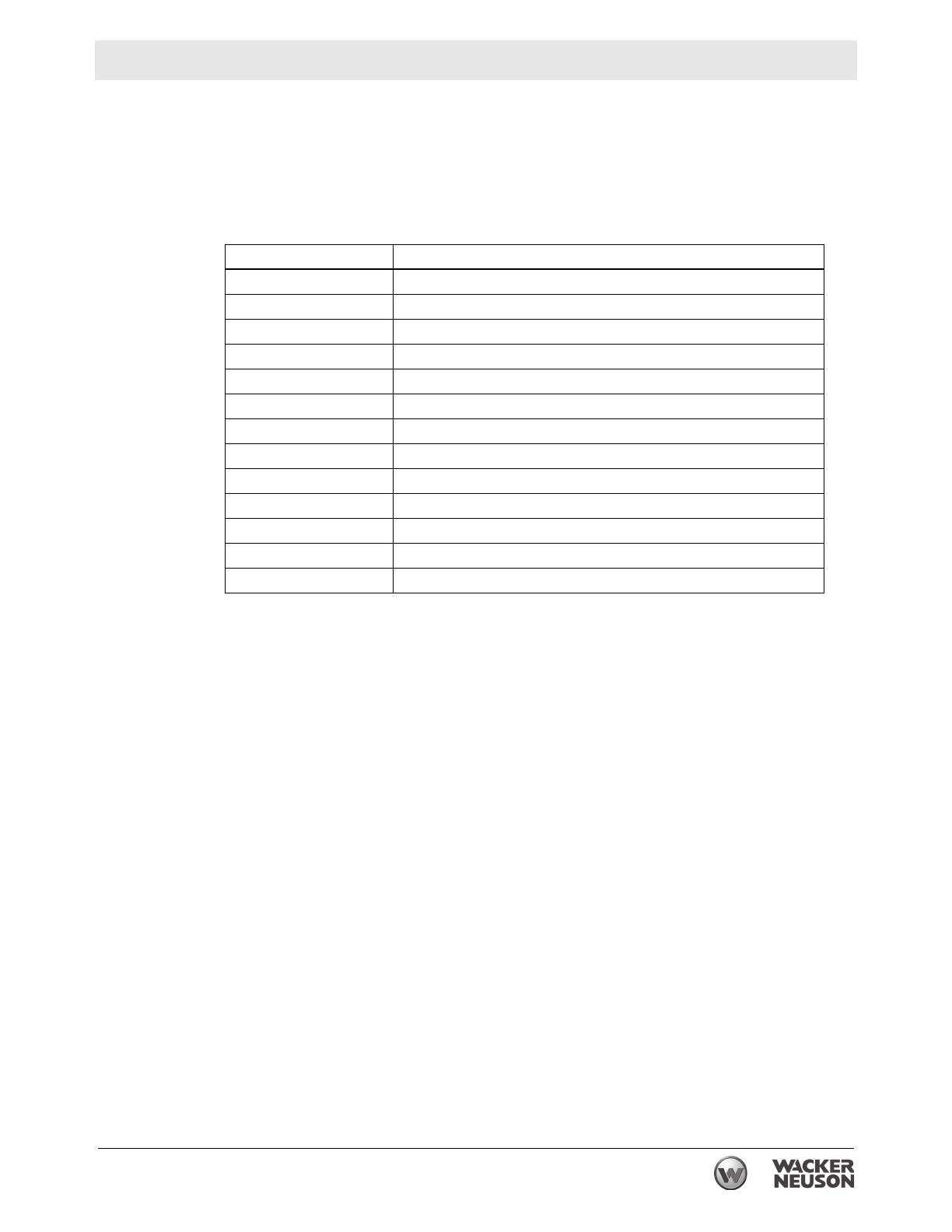
Machines included in this manual:
Machine
documentation
From this point forward in this documentation, Wacker Neuson Production
Americas LLC will be referred to as Wacker Neuson.
Keep a copy of the Operator’s Manual with the machine at all times.
Use the separate Parts Book supplied with the machine to order replacement
parts.
Refer to the separate Repair Manual for detailed instructions on servicing and
repairing the machine.
If you are missing any of these documents, please contact Wacker Neuson to
order a replacement or visit www.wackerneuson.com.
When ordering parts or requesting service information, be prepared to provide
the machine model number, item number, revision number, and serial number.
Expectations
for
information in
this manual
This manual provides information and procedures to safely operate and
maintain the above Wacker Neuson model(s). For your own safety and to
reduce the risk of injury, carefully read, understand, and observe all instructions
described in this manual.
Wacker Neuson expressly reserves the right to make technical modifications,
even without notice, which improve the performance or safety standards of its
machines.
The information contained in this manual is based on machines manufactured
up until the time of publication. Wacker Neuson reserves the right to change any
portion of this information without notice.
Model Part Number
PS2 1503 0009186, 0008801–0008806
PS3 1503 0009187, 0009188, 0008807–0008812
PS2 2203 0009189, 0009190, 0008813–0008818
PS3 2203 0009191, 0009192, 0008819–0008824
PS2 3703 0009193, 0009194, 0008825–0008830
PS3 3703 0009195, 0009196, 0008831–0008836
PS4 3703 0009197, 0009198, 0008837–0008842
PS3 5503 0009199, 0009200, 0008843–0008848
PS4 5503 0009201, 0009202, 0008849–0008854
PS4 7503HH 0009203, 0009204, 0008855–0008860
PS4 7503HF 0009205, 0009206, 0008861–0008866
PS4 11103HH 0009207, 0009208, 0008867–0008870, 0008876, 0008877
PS4 11103HF 0009209, 0009210, 0008871–0008874, 0008878, 0008879
wc_tx001370gb.fm
4
Foreword PS 3-Phase Series
Manufacturers
approval
This manual contains references to approved parts, attachments, and
modifications. The following definitions apply:
Approved parts or attachments are those either manufactured or provided by
Wacker Neuson.
Approved modifications are those performed by an authorized Wacker
Neuson service center according to written instructions published by Wacker
Neuson.
Unapproved parts, attachments, and modifications are those that do not
meet the approved criteria.
Unapproved parts, attachments, or modifications may have the following
consequences:
Serious injury hazards to the operator and persons in the work area
Permanent damage to the machine which will not be covered under warranty
Contact your Wacker Neuson dealer immediately if you have questions about
approved or unapproved parts, attachments, or modifications.
Original Declaration of Conformity
2011-CE-PS 3 Phase_en.fm
EC Declaration of Conformity
Manufacturer
Wacker Neuson Production Americas LLC, N92W15000 Anthony Avenue,
Menomonee Falls, Wisconsin USA
Product
Product
Product category
Product function
Item number
PS2 1503, PS2 2203, PS2 3703, PS3 1503, PS3 2203, PS3 3703,
PS3 5503, PS4 3703, PS4 5503, PS4 7503, PS4 11003
Water Pump Units
To pump fluid
0008802, 0008803, 0008808, 0008809, 0008814,
0008815, 0008820, 0008821, 0008826, 0008827,
0008832, 0008833, 0008838, 0008839, 0008844,
0008845, 0008850, 0008851, 0008856, 0008857,
0008862, 0008863, 0008868, 0008872, 0008876,
0008878
Directives and Standards
We hereby declare that this product meets and complies with the relevant regulations and
requirements of the following directives and standards:
2006/42/EC, 2006/95/EC, 2004/108/EC, EN 809, EN ISO 12100-1/2, EN 60204-1, EN
60335-1, EN 60335-2-41, EN 50366, EN 61000-6.
Authorized Person for Technical Documents
Axel Häret, Wacker Neuson Produktion GmbH & Co. KG, Preußenstraße 41,
80809 München
Menomonee Falls, WI, USA, 09.11.11
William Lahner
Vice President of Engineering
Dan Domanski
Manager, Product Engineering
wc_bo5000184964_05TOC.fm 7
Table of ContentsPS 3-Phase Series
Foreword 3
EC Declaration of Conformity 5
1 Safety Information 9
1.1 Signal Words Used in this Manual ....................................................... 9
1.2 Machine Description and Intended Use ............................................... 9
1.3 Service Safety .................................................................................... 12
1.4 Labels ................................................................................................. 13
2 Lifting and Transporting 15
3 Installation 16
3.1 Components ....................................................................................... 16
3.2 Preparing the Machine for First Use ................................................... 17
3.3 Application Area ................................................................................. 17
3.4 Preparing for installation ..................................................................... 18
3.5 Checks to Make Before Installation .................................................... 19
3.6 Electrical Wiring .................................................................................. 21
4 Operation 24
4.1 Before Operation ................................................................................ 24
4.2 Trial Operation .................................................................................... 25
4.3 Operating current ............................................................................... 25
4.4 Operating voltage ............................................................................... 26
4.5 Vibration ............................................................................................ 26
4.6 Operation ............................................................................................ 26
4.7 Motor Protector ................................................................................... 27
4.8 Emergency Shutdown Procedure ....................................................... 28
8 wc_bo5000184964_05TOC.fm
Table of Contents PS 3-Phase Series
5 Maintenance 29
5.1 Periodic Maintenance Schedule ..........................................................29
5.2 Maintenance and Inspection ...............................................................30
5.3 Storage ................................................................................................30
5.4 Lubricant Inspection and Changing Procedures .................................31
5.5 Replacement Parts ..............................................................................32
5.6 Disassembly and Reassembly ............................................................33
5.7 Graphic (1.5 kW, 2.2 kW, 3.7 kW, 5.5 kW) ..........................................34
5.8 Graphic Components ..........................................................................35
5.9 Disassembly Procedure for 1.5 kW, 2.2 kW, 3.7 kW and
5.5 kW Models ....................................................................................35
5.10 Graphic (7.5 kW, 11 kW) .....................................................................37
5.11 Graphic Components ..........................................................................38
5.12 Disassembly Procedure for 7.5 kW and 11 kW ...................................39
5.13 Troubleshooting ...................................................................................41
6 Technical Data 43
6.1 Standard Specifications .......................................................................43
6.2 Operating Specifications .....................................................................44
7 AEM Safety Manual 49
PS 3-Phase Series Safety Information
wc_si000041gb.fm 9
1 Safety Information
1.1 Signal Words Used in this Manual
This manual contains DANGER, WARNING, CAUTION, NOTICE, and
NOTE signal words which must be followed to reduce the possibility
of personal injury, damage to the equipment, or improper service.
NOTICE: Used without the safety alert symbol, NOTICE indicates a situa-
tion which, if not avoided, could result in property damage.
Note: A Note contains additional information important to a procedure.
1.2 Machine Description and Intended Use
This machine is a submersible water pump. The Wacker Neuson
Submersible Pump consists of an electric motor, an impeller, a strainer,
and a metal casing with ports for water suction and discharge. Power is
supplied to the pump through a corded plug or a hard-wired connection,
depending on the installation. The operator connects hoses to the pump
and routes them so that water is pumped from the work area and
discharged into an appropriate location.
This is the safety alert symbol. It is used to alert you to potential personal hazards.
f Obey all safety messages that follow this symbol.
DANGER
DANGER indicates a hazardous situation which, if not avoided, will result in death
or serious injury.
f
To avoid death or serious injury from this type of hazard, obey all safety messages that
follow this signal word.
WARNING
WARNING indicates a hazardous situation which, if not avoided, could result in
death or serious injury.
f
To avoid possible death or serious injury from this type of hazard, obey all safety mes-
sages that follow this signal word.
CAUTION!
CAUTION indicates a hazardous situation which, if not avoided, could result in
minor or moderate injury.
f
To avoid possible minor or moderate injury from this type of hazard, obey all safety mes-
sages that follow this signal word.
Safety Information PS 3-Phase Series
10 wc_si000041gb.fm
This machine is intended to be used for general de-watering applications.
This machine is intended for the pumping of clear water, or water
containing solids up to the size stated within the products specifications,
and up to the flow, head, and suction lift limits also stated within the
product specifications.
This machine has been designed and built strictly for the intended use
described above. Using the machine for any other purpose could
permanently damage the machine or seriously injure the operator or other
persons in the area. Machine damage caused by misuse is not covered
under warranty.
The following are some examples of misuse:
Pumping flammable, explosive, or corrosive fluids
Pumping hot or volatile fluids that result in pump cavitation
Operating the pump outside of product specifications due to
incorrect diameter hoses, incorrect length hoses, other inlet or
outlet restrictions, or excessive suction lift or head
Using the machine as a ladder, support, or work surface
Using the machine to carry or transport passengers or equipment
Operating the machine outside of factory specifications
Operating the machine in a manner inconsistent with all warnings
found on the machine and in the Operator’s Manual.
This machine has been designed and built in accordance with the latest
global safety standards. It has been carefully engineered to eliminate
hazards as far as practicable and to increase operator safety through
protective guards and labeling. However, some risks may remain even
after protective measures have been taken. They are called residual
risks. On this machine, they may include exposure to:
Electric shock from improper electrical connections or high
voltage
Personal injury from improper lifting techniques
Projectile hazard from discharge
To protect yourself and others, make sure you thoroughly read and
understand the safety information presented in this manual before
operating the machine.
Operating and Electrical Safety
To reduce risk of electric shock, connect only to a properly grounded,
grounding-type receptacle.
Risk of electric shock—this pump has not been investigated for use in
swimming pool areas.
An acceptable motor-control switch shall be provided at the time of
installation according to local codes and regulations.
WARNING
PS 3-Phase Series Safety Information
wc_si000041gb.fm 11
To reduce risk of electric shock, follow instructions in this manual for
proper installation.
CAUTION: This pump may automatically restart. Prior to working on
the pump or control panel, all supply circuits must be disconnected.
CAUTION: Risk of shock—do not remove cord and strain relief.
Operator qualifications
Only trained personnel are permitted to start, operate, and shut down
the machine. They also must meet the following qualifications:
have received instruction on how to properly use the machine
are familiar with required safety devices
The machine must not be accessed or operated by:
•children
people impaired by alcohol or drugs
Personal Protective Equipment (PPE)
Wear the following Personal Protective Equipment (PPE) while
operating this machine:
Close-fitting work clothes that do not hinder movement
Safety glasses with side shields
Hearing protection
Safety-toed footwear
Safety Information PS 3-Phase Series
12 wc_si000041gb.fm
1.3 Service Safety
Service training
Before servicing or maintaining the machine:
Read and understand the instructions contained in all manuals
delivered with the machine.
Familiarize yourself with the location and proper use of all
controls and safety devices.
Only trained personnel shall troubleshoot or repair problems
occurring with the machine.
Contact Wacker Neuson for additional training if necessary.
When servicing or maintaining this machine:
Do not allow improperly trained people to service or maintain the
machine. Personnel servicing or maintaining the machine must
be familiar with the associated potential risks and hazards.
Personal Protective Equipment (PPE)
Wear the following Personal Protective Equipment (PPE) while
servicing or maintaining this machine:
Close-fitting work clothes that do not hinder movement
Safety glasses with side shields
Hearing protection
Safety-toed footwear
In addition, before servicing or maintaining the machine:
Tie back long hair.
Remove all jewelry (including rings).
Replacing parts and labels
Replace worn or damaged components.
Replace all missing and hard-to-read labels.
When replacing electrical components, use components that are
identical in rating and performance as the original components.
When replacement parts are required for this machine, use only
Wacker Neuson replacement parts or those parts equivalent to
the original in all types of specifications, such as physical
dimensions, type, strength, and material.
PS 3-Phase Series Safety Information
wc_si000041gb.fm 13
1.4 Labels
A nameplate listing the model number, item number, revi-
sion number, and serial number is attached to each unit.
Please record the information found on this nameplate so it
will be available should the nameplate become lost or dam-
aged. When ordering parts or requesting service informa-
tion, you will always be asked to specify the model number,
item number, revision number, and serial number of the
unit.
CAUTION
Do not attempt to operate this product before reading the
Operator’s Manual and understanding its contents.
Mishandling of this product may result in explosion, fire, or
electrical shock.
Do not pull on the power cord or use the power cord to lift
the pump.
Always use a dedicated ground leakage circuit breaker.
Be sure to install the ground wire securely.
Be sure to disconnect the power supply before handling
or inspecting the pump.
Never insert your hand into the pump inlet holes while the
pump is connected to the power supply.
MADE IN TAIWAN
Wacker Neuson Corporation
Menomonee Falls, WI 53051 USA
Safety Information PS 3-Phase Series
14 wc_si000041gb.fm
PS Pumps Lifting and Transporting
wc_tx001948gb.fm 15
2 Lifting and Transporting
Do not under any circumstances install or move the pump by
suspending it from the cable assembly. The cable may be damaged,
causing electrical leakage, shock, or fire.
When installing the pump, pay close attention to its center of gravity
and weight. If it is not lowered into place correctly, it may fall and be
damaged or cause injury.
When transporting the pump by hand, be sure to employ manpower
commensurate with the weight of the pump. To avoid back injury when
lifting the pump, bend the knees to pick it up rather than bending your
back only.
Avoid dropping the pump or other strong impact. Lift the pump by
holding it firmly with the hands or by attaching a rope or chain to the
handle.
WARNING
CAUTION
Installation PS 3-Phase Series
16 wc_tx001970gb.fm
3 Installation
3.1 Components
Note: This diagram shows the parts layout of a typical PS (Three-Phase) model. The external appear-
ance and the internal construction may vary slightly, depending on your particular model.
Ref. Description Ref. Description
1 Discharge outlet 8 Lifting handle
2 Coupling 9 Mechanical seal
3 Oil housing 10 Oil plug
4 Lubricant 11 Sleeve
5 Impeller 12 Volute
6 Suction cover 13 Strainer
7 Cable assembly 14 Plate
wc
_
gr000327
7
1
2
8
9
10
11
12
13
14
6
5
4
3
PS 3-Phase Series Installation
wc_tx001970gb.fm 17
3.2 Preparing the Machine for First Use
When the pump is delivered, first perform the following checks:
Inspection
While unpacking, inspect the product for damage during shipment, and
make sure all bolts and nuts are tightened properly.
Specification check
Check the model number to make sure it is the product that was
ordered. Be certain it is the correct voltage and frequency.
Note: If there is any problem with the product as shipped, contact your
nearest dealer or Wacker Neuson representative at once.
Product specifications
Do not operate this product under any conditions other than those for
which it is specified. Failure to observe this precaution can lead to
electrical shock, current leakage, fire, water leakage or other
problems.
3.3 Application Area
If the pump is used for outdoor fountains, garden ponds and similar
places, or to drain a swimming pool, the pump must be supplied my an
isolating transformer or connected to a Residual Current Device (RCD)
with a residual operating current not exceeding 30 mA.
The pump must not be used when people are in the water.
Leakage of pump lubricants may cause pollution of water.
Proper plug must be provided according to local codes and standards.
Refer to wiring diagram.
The supply voltage should be within ± 5% of the rated voltage.
DO NOT use in water temperatures outside the range of 0–40°C (32–
104°F), which can lead to failure, electrical leakage or shock.
The pump should be used only for pumping plain water. The pump
should not be used to pump fluids such as oil, salt water, or organic
solvents.
The pump must never be used to pump explosive liquids and should
never be operated in an area where explosive elements might be
present.
The pump must not be used in a partially disassembled state.
Note: Consult your local dealer or Wacker Neuson representative
before using with any liquids other than those indicated in this
document.
CAUTION
WARNING
Installation PS 3-Phase Series
18 wc_tx001970gb.fm
Critical Pressure
Do not use the pump in an area where the water pressure exceeds the
values given below, as it may damage the pump, or cause a short or
electrical shock.
3.4 Preparing for installation
Before installing the pump at a work site, you will need to have the
following tools and instruments ready:
Insulation resistance tester (megohmmeter)
AC voltmeter
AC ammeter (clamp-on type)
Bolt and nut tighteners
Power supply connection tools (screwdriver or box wrench)
Note: Please also read the instructions that come with each of the test
instruments.
Model Critical Pressure
PS2 1503
PS2 2203
PS2 3703
PS4 3703
PS4 5503
PS3 1503
PS3 2203
PS3 3703
PS3 5503
0.5 MPa (71 PSI)
– discharge pressure during use
= critical pressure
PS4 7503HH
PS4 11003HH
PS4 7503HF
PS4 11003HF
critical pressure = 0.5 MPa (71 PSI)
CAUTION
PS 3-Phase Series Installation
wc_tx001970gb.fm 19
3.5 Checks to Make Before Installation
With the megohmmeter, measure the insulation resistance between
each of the power wires and grounding wire to verify the insulation
resistance of the motor.
Reference insulation resistance: 20MW or greater
Note: The reference insulation resistance (20M
W
or greater) is the
value when the pump is new or has been repaired. For the reference
value after installation, see Maintenance and Inspection.
Precautions During Installation
When installing the pump, pay close attention to its center of gravity
and weight. If it is not suspended properly, it may fall and be damaged
or cause injury.
When transporting the pump manually, be sure to employ manpower
commensurate with the weight of the pump. To avoid back injury when
lifting the pump, bend the knees to pick it up rather than bending your
back only.
Do not under any circumstances install or move the pump by
suspending it from the cable assembly. The cable may be damaged,
causing electrical leakage, shock, or fire.
3.5.1 This pump series is offered with a variety of discharge fittings. Please
refer to the BOM Product Matrix in the Parts Section to identify the type
of discharge fitting used on your pump. Follow procedures noted
below to assure a proper discharge connection.
Threaded Discharge Fitting (BSP) –
Tighten hose coupling or discharge pipe securely and with proper
gaskets.
Quick Disconnect Coupling (QD) –
Assure coupling is tightened securely to pump discharge fitting and
companion coupling is securely fastened with proper gaskets.
Barbed Discharge Fitting (Barb) –
Place hose clamp over hose and push hose to the base of the
discharge fitting. Tighten the hose clamp to secure the hose in place.
3.5.2 Avoid dropping the pump or other strong impact. Lift the pump by
holding it firmly with the hands or by attaching a wire rope (a) or chain
to the handle.
Note: For proper procedures for handling the cable assembly, refer to
Section Electrical Wiring in this manual.
Do not operate the pump dry. Doing so will prevent the pump from
attaining its full potential and may also damage the pump and lead to
a short and electrical shock.
WARNING
CAUTION
CAUTION
Installation PS 3-Phase Series
20 wc_tx001970gb.fm
In order to properly discharge water, provide adequate piping to the
area where the pump is mounted. Improper piping may lead to water
leakage or other malfunctions.Install the pump only in an area that can
maintain a proper water level.
3.5.3 Install the pump only in an area that can maintain a proper water level.
Note: For details on the water level necessary for pump operation,
refer to “Water Level During Operation” in the Operation section.
3.5.4 When using a hose to provide piping to the pump, observe the
following:
Use the shortest possible length of discharge hose and minimize the
number of bends. Verify that the end of the hose (discharge side) is
lifted above the water surface (a). If the end of the hose is submerged
in water, it may cause the water to flow back (b) when the pump has
been stopped. If the end of the hose is located at a level that is lower
than that of the source water surface, water may continue to flow out
even after the pump has been stopped.
Note: Appropriate piping materials must be provided by the user.
Piping materials are not included with the product..
If large quantities of sediment are drawn into the pump, damage
resulting from wear to the pump can lead to current leakage and
electrical shock.
3.5.5 Use the pump in the upright position. To prevent the pump from
becoming submerged in mud, mount it on a block or other firm base if
necessary.
3.5.6 If used in a permanent installation, where the pump is not readily
accessible after installation, please contact Wacker Neuson for a
duplicate nameplate to be installed at the wellhead or on the control
box so that it will be readily visible.
CAUTION
wc
_
gr000329
b
c
wc
_
gr000330
wc
_
gr000328
a
  • Page 1 1
  • Page 2 2
  • Page 3 3
  • Page 4 4
  • Page 5 5
  • Page 6 6
  • Page 7 7
  • Page 8 8
  • Page 9 9
  • Page 10 10
  • Page 11 11
  • Page 12 12
  • Page 13 13
  • Page 14 14
  • Page 15 15
  • Page 16 16
  • Page 17 17
  • Page 18 18
  • Page 19 19
  • Page 20 20
  • Page 21 21
  • Page 22 22
  • Page 23 23
  • Page 24 24
  • Page 25 25
  • Page 26 26
  • Page 27 27
  • Page 28 28
  • Page 29 29
  • Page 30 30
  • Page 31 31
  • Page 32 32
  • Page 33 33
  • Page 34 34
  • Page 35 35
  • Page 36 36
  • Page 37 37
  • Page 38 38
  • Page 39 39
  • Page 40 40
  • Page 41 41
  • Page 42 42
  • Page 43 43
  • Page 44 44
  • Page 45 45
  • Page 46 46
  • Page 47 47
  • Page 48 48
  • Page 49 49
  • Page 50 50
  • Page 51 51
  • Page 52 52
  • Page 53 53
  • Page 54 54
  • Page 55 55
  • Page 56 56
  • Page 57 57
  • Page 58 58
  • Page 59 59
  • Page 60 60
  • Page 61 61
  • Page 62 62

Wacker Neuson PS22203 User manual

Category
Water pumps
Type
User manual

Ask a question and I''ll find the answer in the document

Finding information in a document is now easier with AI