2.4.1 Requirements
WARNING
EQUIPMENT HAZARD!
Rotating shafts and electrical equipment can be hazardous.
All electrical work must conform to national and local
electrical codes. It is strongly recommended that installation,
start up, and maintenance be performed only by trained and
qualified personnel. Failure to follow these guidelines could
result in death or serious injury.
CAUTION
WIRING ISOLATION!
Run input power, motor wiring and control wiring in three
separate metallic conduits or use separated shielded cable
for high frequency noise isolation. Failure to isolate power,
motor and control wiring could result in less than optimum
frequency converter and associated equipment
performance.
For your safety, comply with the following requirements.
•
Electronic controls equipment is connected to
hazardous mains voltage. Extreme care should be
taken to protect against electrical hazards when
applying power to the unit.
•
Run motor cables from multiple frequency
converters separately. Induced voltage from output
motor cables run together can charge equipment
capacitors even with the equipment turned off and
locked out.
Overload and Equipment Protection
•
An electronically activated function within the
frequency converter provides overload protection
for the motor. The overload calculates the level of
increase to activate timing for the trip (controller
output stop) function. The higher the current draw,
the quicker the trip response. The overload
provides Class 20 motor protection. See 8 Warnings
and Alarms for details on the trip function.
•
Because the motor wiring carries high frequency
current, it is important that wiring for mains, motor
power, and control are run separately. Use metallic
conduit or separated shielded wire. Failure to
isolate power, motor, and control wiring could
result in less than optimum equipment
performance.
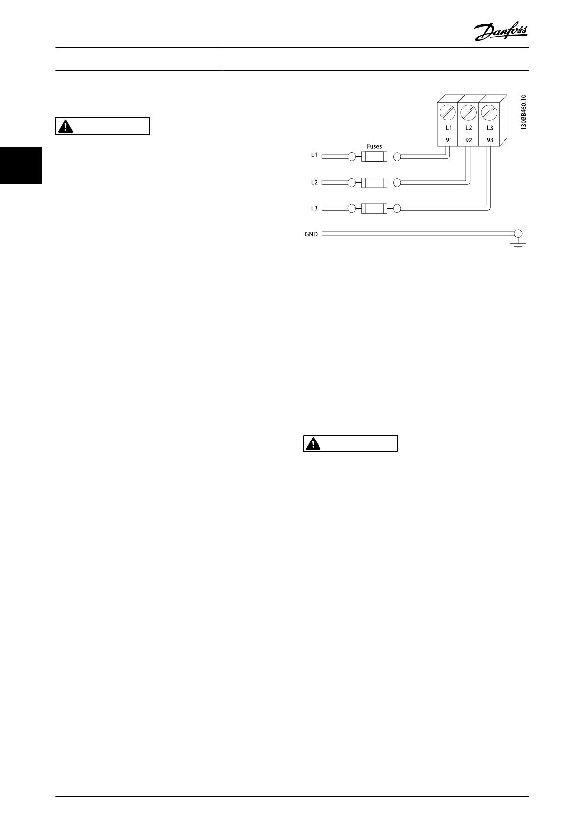
•
All frequency converters must be provided with
short-circuit and over-current protection. Input
fusing is required to provide this protection, see
Illustration 2.6. If not factory supplied, fuses must be
provided by the installer as part of installation. See
maximum fuse ratings in 10.3 Fuse Tables.
Illustration 2.6 Frequency Converter Fuses
Wire Type and Ratings
•
All wiring must comply with local and national
regulations regarding cross-section and ambient
temperature requirements.
•
Danfoss recommends that all power connections
be made with a minimum 75° C rated copper wire.
•
See 10.1 Power-dependent Specifications for
recommended wire sizes.
2.4.2 Earth (Grounding) Requirements
WARNING
GROUNDING HAZARD!
For operator safety, it is important to ground frequency
converter properly in accordance with national and local
electrical codes as well as instructions contained within these
instructions. Ground currents are higher than 3,5mA. Failure
to ground frequency converter properly could result in death
or serious injury.
NOTE
It is the responsibility of the user or certified electrical
installer to ensure correct grounding (earthing) of the
equipment in accordance with national and local electrical
codes and standards.
•
Follow all local and national electrical codes to
ground electrical equipment properly
•
Proper protective grounding for equipment with
ground currents higher than 3,5mA must be
established, see Leakage Current (>3,5mA)
•
A dedicatedground wire is required for input
power, motor power and control wiring
•
Use the clamps provided with on the equipment
for proper ground connections
Installation
VLT
®
AutomationDrive Operating
Instructions
12 MG.33.AJ.02 - VLT
®
is a registered Danfoss trademark
2


