Page is loading ...

WARNING
Do not connect power supply until the fan is completely installed. Disconnect power to fan prior to service or maintenance.
1. This unit has rotating parts and may have sharp edges. Safety precautions should be exercised during installation, operation
and maintenance.
2. Do not
use these fans in hazardous environments where the fan’s electrical system could provide ignition to combustible or
flammable materials.
3. Turn centrifugal impeller by hand to make sure it rotates freely. If the impeller does not rotate freely contact Tjernlund’s customer
service department at 800-255-4208.
4. If using the M-Series in a dryer application it must be periodically inspected. IMPORTANT: Disconnect power to fan prior to ser-
vice or maintenance. Remove dryer duct and remove any lint build-up from the impeller on both inlet and outlet sides of fan.
5. Ducted fans used for exhaust applications must always be vented to the outdoors.
6. CAUTION: “For General Ventilation Use Only. Do Not
Use To Exhaust Hazardous Or Explosive Materials And Vapors.”
7. Rated for air stream temperatures up to 140° F (60° C).
IMPORTANT: All wiring must be in accordance with the National Electrical Code. Verify supply voltage and power consumption of fan
are suitable for circuit fan will be added to.
GUARDS OR DUCTING ON INLET/OUTLET OF FAN MUST BE INSTALLED WHEN THE FAN IS WITHIN REACH OF PERSONNEL
OR WITHIN SEVEN (7) FEET OF WORKING LEVEL OR WHEN DEEMED ADVISABLE FOR SAFETY.
TJERNLUND PRODUCTS, INC.
1601 Ninth Street • White Bear Lake, MN 55110-6794
PHONE (800) 255-4208 • (651) 426-2993 • FAX (651) 426-9547
Visit our web site • www.tjernlund.com
READ OWNERS INSTRUCTIONS
CAREFULLY PRIOR TO
INSTALLATION. DO NOT DESTROY.
M-Series
Metal High Pressure In-Line Duct Booster® Fans
©2014 TJERNLUND PRODUCTS, INC. ALL RIGHTS RESERVED. P/N: 8504147 REV C 09/14
Models
M-4, M-5
M-6, M-8
M-10, M-12
TJERNLUND LIMITED 60 DAY WARRANTY
Tjernlund Products, Inc. warrants to the original purchaser of this product that the product will be free from defects due to faulty material or workmanship for a
period of (60) days from the date of original purchase or delivery to the original purchaser, whichever is earlier. Remedies under this warranty are limited to
repairing or replacing, at our option, any product which shall, within the above stated warranty period, be returned to Tjernlund Products, Inc. at the address
listed below, postage prepaid. THERE ARE NO WARRANTIES WHICH EXTEND BEYOND THE DESCRIPTION ON THE FACE HEREOF, AND TJERNLUND
PRODUCTS, INC. EXPRESSLY DISCLAIMS LIABILITY FOR INCIDENTAL OR CONSEQUENTIAL DAMAGES ARISING FROM THE USE OF THIS PROD-
UCT. THIS WARRANTY IS IN LIEU OF ALL OTHER EXPRESS WARRANTIES AND NO AGENT IS AUTHORIZED TO ASSUME FOR US ANY LIABILITY
ADDITIONAL TO THOSE SET FORTH IN THIS LIMITED WARRANTY. IMPLIED WARRANTIES ARE LIMITED TO THE STATED DURATION OF THIS LIM-
ITED WARRANTY. Some states do not allow limitation on how long an implied warranty lasts, so that limitation may not apply to you. In addition, some states
do not allow the exclusion or limitation of incidental or consequential damages, so that above limitation or exclusion may not apply to you. This warranty gives
you specific legal rights and you may also have other rights which may vary from state to state. Send all inquiries regarding warranty work to Tjernlund
Products, Inc. 1601 9th Street, White Bear Lake, MN 55110-6794. Phone (651) 426-2993 • (800) 255-4208 • Fax (651) 426-9547 • Email [email protected].
SPECIFICATIONS
Model
Volts Watts Amps Free Air CFM (0” w.c.)
M-4 120 100 0.9 200
M-5 120 98 0.9 238
M-6 120 125 1.1 530
M-8 120 210 1.8 670
M-10 120 260 2.1 810
M-12 120 295 2.5 1050

INSTALLATION INSTRUCITIONS
NOTE: Electrical cord is 6.5 feet (2 meters).
1. Cut and adhere foam gasket on inlet and outlet collars of fan, (See Diagram A).
2. Make sure fan is mounted with air flow direction arrow pointing in the right direction. The air flow exits opposite motor side, (See Diagram B)
3. Use included screws to fasten fan to mounting bracket. Fasten mounting bracket against a solid surface with proper orientation and
air flow direction in mind, (See Diagram C).
WIRING DIAGRAMS
Connection with Flex Duct
Use Nylon Ties and Over-Wrap
with Duct Tape
Use Sheet Metal Screws (1” Max) and
Over-Wrap with Duct Tape
Encircle with Perforated Plumber’s
Strap and Secure Tightly
Mounting with Perforated Strap
Connection with Rigid Duct
DIAGRAM B DIAGRAM C
DIAGRAM A
Rotation
Arrow
Motor
Air Flow
Direction
Arrow
Air Flow
MODEL SCP SPEED CONTROL
The optional SCP Speed Control is a convenient and easy
way to vary the speed of the M-Series fans. The SCP is fac-
tory calibrated for use with Tjernlund’s M & P series high
pressure fans. Plug fan into speed control and plug speed
control into 115 VAC outlet.
INTERNAL WIRING
If it is necessary to hard-wire fan, remove power cord and
follow diagram below. IMPORTANT: All wiring must be in
accordance with the National Electrical Code. Verify sup-
ply voltage and power consumption of fan are suitable for
circuit fan will added to.
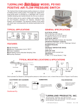
(OPTIONAL PS1503 DUCT AIRSTAT SWITCH)
The Tjernlund PS1503 Duct Airstat is used to automatically activate Duct Booster®
fans by sensing positive pressure in a forced air heating and/or cooling system.The
single pole, single throw, snap-acting switch is activated by a diaphragm with a factory
installed sampling probe inserted directly into the duct or plenum.
/

