Page is loading ...

/
Marley MH Fluid Cooler
/
User Manual 05-116E


3
Contents
Fluid Cooler Location ............................................................................. 5
Fluid Cooler Shipment ............................................................................ 6
Receiving Fluid Cooler ........................................................................... 6
Hoisting Fluid Cooler .............................................................................. 6
Fluid Cooler Installation .......................................................................... 7
Motor Wiring ........................................................................................... 8
Mechanical Equipment ......................................................................... 11
Fluid Cooler Start-Up ........................................................................... 13
Fluid Cooler Operation ......................................................................... 15
Wintertime Operation ........................................................................... 16
Water Treatment ................................................................................... 20
Fluid Cooler Cleaning ........................................................................... 21
Blowdown ............................................................................................. 21
Belt Adjustment .................................................................................... 22
Sheave Alignment ................................................................................ 24
Fluid Cooler Maintenance .................................................................... 25
Seasonal Shutdown Instructions .......................................................... 28
Prolonged Shutdown ............................................................................ 29
Troubleshooting .................................................................................... 32
Additional Information .......................................................................... 34
Note
This manual contains vital information for the proper installation
and operation of your fluid cooler. Carefully read the manual before
installation or operation of the fluid cooler and follow all instructions.
Save this manual for future reference.
Indicates presence of a hazard which can cause severe personal
injury, death or substantial property damage if ignored.
Indicates presence of a hazard which will or can cause personal injury
or property damage if ignored.
Indicates special instructions on installation, operation or maintenance
which are important but not related to personal injury hazards.
Warning
Caution
Note
The following defined terms are used throughout this manual to bring at-
tention to the presence of hazards of various risk levels, or to important
information concerning the life of the product.

4
Preparation
The Marley MH Fluid Cooler with CoolBoost™, purchased for this instal-
lation represents the current state of the art in crossflow, induced draft
fluid cooler design. Thermally and operationally, it is the most efficient
fluid cooler of its class.
These instructions—as well as those offered separately on motors, fans,
Geareducer
®
, couplings, drive shafts, float valves, pumps, etc.—are in-
tended to assure that the fluid cooler serves you properly for the maximum
possible time. Since product warrantability may well depend upon your
actions, please read these instructions thoroughly prior to operation.
If you have questions about the operation and/or maintenance of this
product, and you don’t find the answers in this manual, please contact
your Marley sales representative. When writing for information, or when
ordering parts, please mention product serial number shown on the name-
plate located on the access door.
Safety First
The location and orientation of the fluid cooler can affect the safety of those
responsible for installing, operating or maintaining the fluid cooler. However,
since SPX Cooling Technologies does not determine the location or orienta-
tion of the fluid cooler, we cannot be responsible for addressing those safety
issues that are affected by the fluid cooler’s location or orientation.
WARNING
The following safety issues should be considered by those responsible
for designing the tower installation.
• accesstoandfromthefandeck
• accesstoandfrommaintenanceaccessdoors
• thepossibleneedforladders(eitherportableorpermanent)to
gainaccesstothefandeckormaintenanceaccessdoors
• thepossibleneedforhandrailsaroundthefandeck
• thepossibleneedforexternalaccessplatforms
• potentialaccessproblemsduetoobstructionssurroundingthetower
• lockoutofmechanicalequipment
• thepossibleneedforsafetycagesaroundladders
• theneedtoavoidexposingmaintenancepersonneltothepotentially
unsafe environment inside the fluid cooler
Warning

5
Preparation
Itisnotintendednorassumedthataccesstothefandeckonsingle-ow
models—Models MHF702 thru MHF705—is needed or necessary.
Those are only some of the safety issues that may arise in the design
process. SPX strongly recommends that you consult a safety engineer
to be sure that all safety considerations have been addressed.
Several options are available that may assist you in addressing some of
these personnel safety concerns, including:
• Louver face distribution basin access platform with ladder and handrail.
• Louver face redistribution basin level access platform with ladder and
handrail.
• A handrail system around the perimeter of the fan deck with either one
or two ladders for access to the deck. Double-flow models MHF706
and MHF707 only.
• Extended fan deck that provides additonal access around one end
of the fan cylinder opposite the fan deck access ladder. Double-flow
models MHF706 and MHF707 only.
• Ladder extensions—used where the base of the tower is elevated.
• Safety cages for ladders.
• External lube lines.
• Access door platform.
• Motor located outside the tower. Double-ow models MHF706 and
MHF707 with Geareducer drive only.
• External motor access platform. Double-ow models MHF706 and
MHF707 with Geareducer drive only.
• Plenum walkway. Double-ow models MHF706 and MHF707 only.
Standard on all other models.
• Mechanical equipment access platform.
Fluid Cooler Location
Space available around the fluid cooler should be as generous as possible
to promote ease of maintenance—and to permit freedom of airflow into
and through the fluid cooler. If you have questions about the adequacy
of the available space and the intended configuration of the fluid cooler,
please contact your Marley sales representative for guidance.
Prepare a stable, level support foundation for the fluid cooler, utilizing
weight, wind load, and dimensional information appearing on appropri-
ate Marley submittal drawings. Supports must be level to insure proper
operation of the fluid cooler.
Note
➠

6
The fluid cooler must be located at such distance and direction to
avoid the possibility of contaminated fluid cooler discharge air be-
ingdrawnintobuildingfreshairintakeducts.Thepurchasershould
obtain the services of a Licensed Professional Engineer or Registered
Architect to certify that the location of the fluid cooler is in compli-
ance with applicable air pollution, fire and clean air codes.
Fluid Cooler Shipment
Unless otherwise specified, the MH Fluid Cooler ships by truck (on flat
bed trailers), which lets you receive, hoist, and install the tower in one
continuous operation. Single-cell single-flow fluid coolers ship on one
truck. Double-flow and multicell fluid coolers, depending on their size,
may require more than one truck.
Responsibility for the condition of the fluid cooler upon its arrival belongs to
the trucker—as does the coordination of multiple shipments, if required.
Receiving Fluid Cooler
Prior to unloading the fluid cooler from the delivering carrier, inspect the
shipment for evidence of damage in transit. If damage is apparent, note
the freight bill accordingly. This will support your future recovery claim.
Find and remove the installation instruction drawings and bills of mate-
rial located in a plastic bag in the water collection basin. This information
should be kept for future reference and maintenance purposes.
Hoisting Fluid Cooler
All MH Fluid Cooler models must use hoist clips and overhead lifting for
handling assembled fluid cooler. Forklifting from base of fluid cooler
is not permitted. The clips for the top modules are located at the fan
deck level. The clips for the lower modules are located at the bottom of
the modules at the water collection basin. A Hoisting-Installation label
which has hoisting dimensional information is located on the side casing
near the tower centerline. Remove tower from the carrier and hoist into
place according to the instructions on the label.
MH Fluid Cooler upper and lower modules must be hoisted and set
separately. Do not preassemble modules prior to hoisting.
Installation
Warning
Caution

7
Hoisting clips are provided for ease of unloading and positioning the
uidcooler.Foroverheadliftsorwhereadditionalsafetyisrequired,
safety slings should also be placed under the fluid cooler modules.
Under no circumstances should you combine the top and bottom
modules of modular models and attempt to hoist them at the same
time by utilizing the hoisting clips alone!
Fluid Cooler Installation
These installation instructions are intended to help you prepare be-
foreyouruidcoolerarrives.Ifdiscrepanciesexistbetweenthese
instructions and those shipped with the fluid cooler, the instructions
shipped with the fluid cooler will govern.
1. Prior to placement of the fluid cooler, confirm that the supporting
platform is level, and that the anchor bolt holes are correctly located
in accordance with Marley drawings.
2. Place bottom module on your prepared supports, aligning anchor bolt
holes with those in your supporting steel. Make sure that the orientation
agrees with your intended piping arrangement. Attach fluid cooler to
supporting steel with
3
⁄4" diameter bolts and flat washers (by others).
See support drawing for location and quantity. Position flat washers
between the bolt head and the fluid cooler basin flange.
3. Before setting top module in place on bottom module, clean any
debris from the underside of the top module fill, skid and beams and
from the top of the bottom module and remove shipping cover from
bottom of top module—replace fasteners at side of module to pre-
vent leaks. Place top module on the top peripheral bearing surface
(factory-installed gasket) of bottom module, aligning mating holes as
it is set in place. Attach top module to bottom module with fasteners
provided according to drawings shipped with your fluid cooler.
4. Connect the recirculation piping with rubber boot shipped with the
bottom module piping according to drawings shipped with you fluid
cooler.
5. Attach makeup water supply piping to appropriately-sized float valve
connection located in collection water basin side wall. Install the drain
and overflow according to drawings shipped with your fluid cooler.
If you wish to pipe overflow and drain water to a remote discharge
point, make those connections at this time also.
Note
Installation
Warning
➠

8
Fasteners and components provided by others that are to be attached
to the tower must be compatible with the cooling tower materials—
i.e. fasteners in a stainless steel cold water basin must be stainless
steel.
6. Attach process fluid supply and return piping to the coil. Field piping
connection is an NPT male connection at the coil. A welded connec-
tion requires removing the threaded portion of the coil.
Forweldedconnectionsprotectadjacentareasfromexcessiveheat
andsparksordamagemayoccur.
7. Wire motor(s) and recirculation pump(s) in accordance with wiring
diagram.
For maintenance/safety purposes, SPX Cooling Technologies recom-
mendsalockouttypedisconnectswitchforallmechanicalequipment.
In addition to a disconnect switch, the motor should be wired to main
power supply through short circuit protection, and a magnetic starter
with overload protection.
Motor Wiring
Wire motor leads as shown on the motor nameplate matching the supply
voltage. Do not deviate from the motor nameplate wiring.
Either of following symbols may be shown on the motor nameplate –
Δ, Δ Δ
, Y, or YY. These symbols represent how the motor is constructed on
the inside and in no way have anything to do with a Delta or Wye electrical
distribution system serving the motor.
When using a starter:
• Set motor overload protection to 110% of motor nameplate amps.
This setting allows the fan motor to operate during cooler weather.
During cooler weather it is common for the motor to draw 6 to
10% higher than nameplate amps. High amps are common during
tower commissioning when the tower is dry and the ambient air
temperature is cool.
Note
Caution
Warning
Installation

9
• Do not start the motor more than six times per hour. Short cycling
the tower will cause fuses, breakers or O.L.s to operate and will
decrease motor life.
When using a two-speed starter:
• Motor rotation must be the same at slow speed and high speed.
• Single winding motor requires a starter with a shorting contactor.
• Two-winding motor requires a starter with out a shorting
contactor.
• All two-speed starters must have a 20 second time delay relay
when switching from high speed to low speed.
• Do not start the motor more than six times per hour (each low
speed start and each high speed start count as one start).
When using a VFD:
Before beginning, ensure that the motor is rated for “Inverter Duty”
perNEMAMG-1,part31.
• Set the VFD solid state overload protection to 119% of motor
nameplate amps and set “maximum current parameter” in the
VFD to motor nameplate amps. “Maximum current parameter” will
reduce fan speed and limit amp draw to nameplate amps during
cold weather operation. If furnished with a mechanical O.L. set this
at 110% over motor nameplate amps.
• Motor rotation must be the same in both VFD mode and By-pass
mode.
• If cable distance between the VFD and motor is greater than 100
feet a DV/DT output lter is recommended to avoid damage to the
motor. 100 feet distance is based on our eld experience, the VFD
manufacture may state different distances and distance does vary
depending on the VFD manufacture.
• Program the VFD for variable torque output. Flux vector and con-
stant torque modes may damage the gearbox.
• Do not start and stop the motor using the safety switch at the motor.
If the drive is being commanded to run and the load side is cycled
ON and OFF with the safety switch this may damage the VFD.
Using a VFD in cooling applications has advantages over traditional single
or two speed motor control. A VFD can reduce the cost of electrical en-
ergy being used and provide better temperature control. In addition, it
reduces the mechanical and electrical stress on the motor and mechanical
➠
Installation
Note

10
equipment. Electrical savings can be large during periods of low ambient
temperature when the cooling requirement can be satisfied at reduced
speeds. To benefit from these advantages, it is important that the drive
be installed correctly.
Marley supplies VFD and VFD controls specically designed for our cooling
products. If you have purchased a Marley VFD and/or controls package,
please follow the instructions in the User Manual for that system. Most
VFD problems can be avoided by purchasing the Marley drive system. If
you are installing a VFD other than the Marley drive, please refer to that
drives installation manual.
ImproperuseofaVFDmaycausedamagetoequipmentorpersonal
injury. Failure to correctly install the VFD drive will automatically void
allwarrantiesassociatedwiththemotorandanyequipmentthatis
eitherelectricallyormechanically(directly)attachedtotheVFDdrive
system. The length of this warranty avoidance will be contingent on
properly installing the VFD system and repairing any damage that
may have occurred during its operation. SPX Cooling Technologies
does not assume responsibility for any technical support or damages
forproblemsassociatewithnon-MarleybrandVFDsystems.
Changing the operational fan speed from the factory settings could
cause the fan to operate in an unstable region which may result in
damagetotheequipmentandpossibleinjury.
Warning
Warning
Installation

11
Mechanical Equipment:
The fluid cooler is designed to operate at full speed and half speed.
Warranty is void if the tower is operated at speeds which cause
damagingvibrationstothetowerandassociatedequipment.When
utilizingavariablefrequencydrive,thetowermustbetestedacross
thefullrangeofspeedsandcheckedagainstCTIguidelinesforex-
cessive vibration. Speed ranges not meeting these guidelines must
belockedoutintheVFD.
Always shut off electrical power to the tower fan motor prior to
performing any maintenance on the tower. Any electrical switches
shouldbelockedoutandtaggedouttopreventothersfromturning
thepowerbackon.
1. If equipped, check oil level in accordance with the Geareducer User
Manual for the Geareducer. (Although the Geareducer was filled to the
proper level at the factory, tipping during shipment and hoisting may
have caused some loss of oil.) If oil is required, fill Geareducer to the
proper level with approved lubricant. (See Geareducer User Manual )
Check oil level at the Geareducer or dipstick (standpipe located on fan
deck, if so equipped) to confirm that the proper level is indicated.
2. On double-flow models—MHF706 and MHF707—install fan cylinder
and two-piece fan guard according to the installation drawing shipped
with the fluid cooler.
Improper installation of the fan cylinder and fan guard will destroy the
structural integrity of the fan guard. Failure of the fan guard could allow
operating or maintenance personnel to fall into the rotating fan.
3. Spin the fan(s) manually to assure that all fan blades properly
clear the inside of the fan cylinder. If equipped, observe the ac-
tion of the coupling (or drive shaft couplings) to be sure that the
motor and Geareducer are properly aligned. If necessary, cor-
rect the alignment in accordance with the included manual.
For belt drive equipped models observe the action of the sheaves and
belts to be sure that the motor is properly aligned with the fan sheave.
See Belt Tensioning and Sheave Alignment on pages 22 thru 24.
Warning
➠
Installation
Warning
Warning

12
It is essential that the fan cylinder and fan guard be installed in ac-
cordance with the drawings shipped with the tower. Do not force the
fan cylinder out of round.
4. Momentarily bump (energize) the motor(s) and observe rotation of the
fan(s). If rotation is backwards, shut off the fan and reverse two of the
three primary leads supplying power to the motor.
Iftowerisequippedwithatwo-speedmotor,checkforproperrota-
tionatbothspeeds.Checkalsotoseethatstarterisequippedwitha
20 second time delay which prevents direct switching from high
speed to low speed. If the fan is intended to be reversed for deicing
purposes,make sure thatthe starterisequippedwith a 2minute
time delay between changes of direction. These delays will prevent
abnormal stress frombeing applied tothe mechanical equipment
and the electrical circuit components.
5. Run the motor and observe the operation of the mechanical equip-
ment. Operation should be stable, and, if equipped, there should be
no evidence of oil leakage from the Geareducer.
6. If equipped with belt drive check the torque on the fan and motor sheave after
10 - 60 hrs. of operation. See Bushing Fastener Torque Values on page 25.
If the water supply system is not being operated—or if there is no
heat load on the system—motor amps read at this time may indicate
anapparentoverloadofasmuchas10–20%.Thisisbecauseofthe
increased density of unheated air flowing through the fan. Determi-
nation of an accurate motor load should await the application of the
design heat load.
Note
Caution
Installation
Note

13
Fluid Cooler Start-Up
Amongothersources,outbreaksofLegionnaires’Diseasehavereport-
edly been traced to cooling towers and fluid coolers. Maintenance and
water treatment procedures that prevent amplification and dissemina-
tion of Legionella and other airborne bacteria should be formulated
and implemented BEFORE systems are operated and continued
regularlythereaftertoavoidtheriskofsicknessordeath.
Water System:
1. New installations should be cleaned and treated with biocides by a
water treatment expert before startup.
2. Remove any and all accumulated debris from fluid cooler. Pay par-
ticular attention to inside areas of collection water basin, distribution
water basins, louvers and drift eliminators. Make sure that cold water
suction screens are clear and properly installed.
3. Fill the water system to an approximate depth of 8″ (203 mm) in the
depressed area of the collection water basin. This is the recommended
operating water level. Adjust the oat valve so that it is 75% open at
that level. Continue filling the system until the water reaches a level
approximately 1/8″ (3 mm) below the lip of the overflow.
4. Start your pump(s) and check for proper rotation as indicated by
the arrow on the pump cover, observe system operation. A certain
amount of “pump-down” of the basin water level will occur before
water completes the circuit and begins to fall from the fill in the up-
per module. The amount of initial pump-down may be insufficient to
cause the float valve to open. However, you can check its operation
by pressing down on the operating lever to which the stem of the float
valve is attached.
Some trial and error adjustment of the float valve may be required to
balance the makeup water with tower operation. Ideally, the float valve
setting will be such that no water is wasted through the overflow at
pump shutdown. However, the water level after pump start-up must
be deep enough to assure positive pump suction.
5. Open the valve on the tower bleed line and adjust bleed to the recom-
mended rate. See Water Treatment section on page 20.
6. Continue pump operation for about 15 minutes, after which it is rec-
ommended that the water system be drained, flushed and refilled.
Operation
Warning
➠

14
7. While operating the recirculating water pump(s) and prior to operat-
ing the cooling tower fan, execute one of the two alternative biocidal
treatment programs described in the following:
• Resume treatment with the biocide which had been used prior
to shutdown. Utilize the services of the water treatment supplier.
Maintain the maximum recommended biocide residual (for the
specific biocide) for a sufficient period of time (residual and time
will vary with the biocide) to bring the system under good biological
control or
• Treat the system with sodium hypochlorite to a level of 4 to 5 mg/L
(ppm) free chlorine residual at a pH of 7.0 to 7.6. The chlorine re-
sidual must be held at 4 to 5 mg/L (ppm) for six hours, measurable
with standard commercial water test kits.
If the fluid cooler has been in operation and then shut down for a
duration of time and not drained, perform one of the two previous
biocidal treatment programs directly to the fluid cooler storage vessel
(collection basin, drain down tank, etc.) without circulating stagnant
water over the cooling tower fill or operating the cooling tower fan.
After biocidal pretreatment has been successfully completed, cooling
water may be circulated over the tower fill with the fan off.
When biocidal treatment has been maintained at a satisfactory level for
at least six hours, the fan may be turned on and the system returned
to service. Resume the standard water treatment program, including
biocidal treatment.
Operation

15
Fluid Cooler Operation
General:
The cold process fluid temperature obtained from an operating fluid cooler
will vary with the following influences:
1. Heat load: With the fan in full operation, if the heat load increases,
the cold process fluid temperature will rise. If the heat load reduces,
the cold process fluid temperature will reduce.
Note that the number of degrees (“range”) through which the fluid
cooler cools the process fluid is established by the system heat load
and the amount of fluid being circulated, in accordance with the follow-
ing formula—formula is only valid for 100% water as process uid:
The fluid cooler establishes only the cold process fluid temperature
attainable under any operating circumstance.
2. Air wet-bulb temperature: Cold process fluid temperature will also
vary with the wet-bulb temperature of the air entering the louvered
faces of the fluid cooler. Reduced wet-bulb temperatures will result
in colder process fluid temperatures. However, the cold process
fluid temperature will not vary to the same extent as the wet-bulb.
For example, a 20°F reduction in wet-bulb may result in only a 15°F
reduction in cold process fluid temperature.
3. Fluid flow rate: Increasing the process fluid flow rate (GPM) will cause
a slight elevation in cold process fluid temperature, while reducing
the fluid flow rate will cause the cold process fluid temperature to
decrease slightly. However, at a given heat load (see formula above),
process fluid flow reductions also cause an increase in the incoming
hot process fluid temperature and thermal range.
Undernocircumstancesshouldtherecirculationwaterpump(s)be
cycled to control process fluid temperature. It is recommenced that
while process fluid is being circulated through the coil the fluid cooler
recirculation water system always be in operation.
Operation
Range – °F =
Heat Load (Btu/hr)
GPM x 500
or — in SI units
Range – °C =
Heat Load (kilowatts)
Liters/sec x 4.187
Note
➠

16
4. Air flow rate: Reducing air flow through the fluid cooler causes the cold
process fluid temperature to rise. This is the recommended method
by which to control leaving process fluid temperature.
If your fluid cooler is equipped with a single-speed motor, the motor
may be shut off when the process fluid temperature becomes too
cold. This will cause the process fluid temperature to rise. When the
fluid temperature then becomes too warm for your process, the motor
can be restarted.
Whenoperatinginthismodecaremustbetakennottoexceedatotal
fanaccelerationtimeof30secondsperhour.
Fan cycling limits: From a dead stop, determine the number of sec-
onds it takes the fan to arrive at full speed. Divide this number into 30
to determine the allowable number of starts per hour. Considering the
normal fan and motor sizes utilized on MH Fluid Coolers, anticipate
that approximately 4 to 5 starts per hour are allowable.
If your fluid cooler is equipped with a two-speed motor(s), you will
enjoy greater opportunity for process temperature control. When the
process fluid temperature becomes too cold, switching the fan to
half-speed will cause the cold process fluid temperature to rise—
stabilizing at a temperature a few degrees higher than before. With a
further reduction in fluid temperature, the fan may be cycled alternately
from half-speed to off—subject to the same constraint of 30 seconds
of allowable acceleration time per hour as outlined above.
For greater insight on process fluid temperature control, please read
“Cooling Tower Energy and its Management”, Technical Report
#H-001-A, available at spxcooling.com.
Wintertime Operation:
The Marley film-fill system used in the MH Fluid Cooler has air entrance
louvers that are molded as an integral part of the fill. This feature makes
these fluid coolers very forgiving of cold weather operation, even at the low
temperature and reduced load conditions encountered in low temperature
applications. Nevertheless, during operation in subfreezing weather the op-
portunity exists for ice to form in the colder regions of the fluid cooler.
Operation
Caution

17
Slushy, transitory ice forms routinely in the colder regions of the fill
of low temperature towers, and is visible through the tower louvers.
Such ice normally has no adverse effect on fluid cooler operation,
butitsappearanceshouldbeasignaltotheoperatortoundertake
ice control procedures.
It is the operator's responsibility to prevent the formation of destruc-
tive(hard)iceontheuidcoolerll.Certainguidelines should be
followed:
1. Do not allow the fluid cooler's leaving process fluid temperature to
drop below 45°F. If such low temperature operation is necessary or
beneficial to your process, establish the minimum allowable level as
follows:
During the coldest days of the first winter of operation, observe whether
any ice is forming on the louver face, particularly near the bottom
part of the louver face. If hard ice is present on the louvers, you must
increase the allowable cold water temperature.
If the minimum allowable cold process fluid temperature is estab-
lished at or near minimum heat load, it should be safe for all operat-
ing conditions.
Having established the minimum allowable cold water temperature,
maintaining that temperature can be accomplished by fan manipulation,
as outlined in Item 4 under Fluid Cooler Operation.
2. As cold air enters the louvers, it causes the water flowing over the fill
to be drawn inward toward the center of the tower. Thus, under fan
operation, the louvers and lower periphery of the tower structure remain
partly dry, seeing only random splashing from within the tower—plus
normal atmospheric moisture from the entering air. Such lightly wetted
areas are most subject to freezing.
Therefore, if excessive ice forms on the louvers, stop the fan for a few
minutes. With the fan off, the water flow will increase in the vicinity of
the louvers and reduce the ice buildup.
3. Under extended extreme cold conditions, it may be necessary to op-
erate the fan in reverse. This forces warm air out through the louvers,
melting any accumulated ice—adequate heat load must be available.
➠
Operation
Note
Caution

18
Reversal may be at either full or half speed; however, reversal at half
speed is recommended. Reverse operation of the fan should be used
sparingly and should only be used to control ice, not to prevent it.
Reverse fan operation should not need to exceed 1 or 2 minutes. Monitor-
ing is required to determine the time required to melt accumulated ice.
Reverse operation of fans for prolonged periods during subfreezing
weather can cause severe damage to fans and fan cylinders. Ice can
accumulate inside fan cylinders at fan blade plane of rotation and
fanbladetipswilleventuallystrikethisringofice,damagingthefan
blades or cylinder. Ice can also accumulate on fan blades and be
thrownoff,damagingfancylinderorblades.Allowaminimumof10
minute delay between reverse operation and forward operation during
subfreezing weather to permit ice to dissipate from fan blades and
fancylinders.SeeFanDriveCautionnoteonpage12forfanspeed
change and reversing precautions.
Intermittent Wintertime Operation:
If periods of shutdown (nights, weekends, etc.) occur during freezing
weather, measures must be taken to prevent the water in the cold water
basin—and all exposed pipework—from freezing. Several methods are
used to combat this, including automatic basin heater systems and pump
freeze protection systems available from Marley.
Basin heaters systems will not prevent the coil from freezing.
Unless some means of freeze prevention is incorporated into your
system,thetowerbasinandexposedpipeworkshouldbedrainedat
the beginning of each wintertime shutdown period.
If tower basin is drained, verify that all basin heaters have been shut
off either by automatic cutoff or disconnect switch.
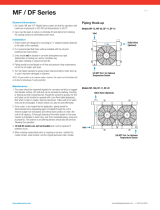
Protection Against Coil Freezing:
Ethylene and propylene glycol solutions are the best means to protect the
coil from freezing. The following table provides the coil volume for each
MH Fluid Cooler model. MHF706 and MHF707 coil volumes are for both
coils added together.
Operation
Warning
Warning
Warning
Caution

19
When the use of industrial antifreeze solutions is not possible, the system
must be operated to meet both of the following conditions.
1. Maintain sufficient flow rate through the coil.
2. Maintain sufficient heat load on the process fluid. Fluid exiting the
coil must be maintained at or above 45°F. Cycling of the recirculation
pump should not be used to control process temperatures.
Draining the coil is not acceptable as a normal method of freeze
protection—draining promotes corrosion inside the coil tubes. Drain-
ing is acceptable in an emergency if the coil is not protected by an
antifreeze solution.
It is recommended that you discuss your freeze prevention options with
your local Marley sales representative.
Operation
Model
Coil Volume
US Gallons
Model
Coil Volume
US Gallons
MHF702__061 65 MHF705__061 235
MHF702__081 85 MHF705__081 315
MHF702__101 105 MHF705__101 390
MHF702__121 125 MHF705__121 465
MHF702__062 75 MHF705__062 285
MHF702__082 100 MHF705__082 380
MHF702__102 120 MHF705__102 470
MHF702__122 150 MHF705__122 565
MHF703__061 85 MHF706__061 390
MHF703__081 115 MHF706__081 500
MHF703__101 140 MHF706__101 610
MHF703__121 170 MHF706__121 725
MHF703__062 100 MHF706__062 475
MHF703__082 130 MHF706__082 610
MHF703__102 165 MHF706__102 750
MHF703__122 200 MHF706__122 885
MHF704__061 160 MHF707__061 450
MHF704__081 210 MHF707__081 580
MHF704__101 260 MHF707__101 710
MHF704__121 310 MHF707__121 840
MHF704__062 190 MHF707__062 570
MHF704__082 250 MHF707__082 740
MHF704__102 315 MHF707__102 905
MHF704__122 375 MHF707__122 1071
Caution

20
Water Treatment and Blowdown
Maintaining Water Quality:
The steel used in MH Fluid Cooler's has been galvanized with a heavy
zinc coating averaging 2.0 mils in thickness. Other materials used (PVC
fill, drift eliminators, and louvers, aluminum fans, cast iron Geareducer,
etc.) are selected to offer maximum service life in a “normal” fluid cooler
environment, defined as follows:
Recirculating water with a pH between 6.5 and 8; a chloride content (as
NaCl) below 500 ppm; a sulfate content (SO4) below 250 ppm; total al-
kalinity (as CaCO
3
) below 500 ppm; calcium hardness (as CaCO
3
) above
50 ppm; no significant contamination with unusual chemicals or foreign
substances; and adequate water treatment to minimize scaling.
• Startup Conditions: The water conditions during initial uid cooler op-
eration are crucial in preventing premature corrosion of galvanized steel
(white rust). For at least the first eight weeks of operation, pH should
be controlled between 6.5 and 8.0 with hardness and alkalinity levels
between 100 and 300 ppm (expressed as CaCO
3
).
• Chlorine (if used) shall be added intermittently, with a free residual not
to exceed 1 ppm—maintained for short periods. Excessive chlorine
levels may deteriorate sealants and other materials of construction.
• An atmosphere surrounding the tower no worse than “moderate indus-
trial”, where rainfall and fog are no more than slightly acid, and they do
not contain significant chlorides or hydrogen sulfide (H2S).
• Many proprietary chemicals exist for control of scale, corrosion, and
biological growth and should be used prudently. Also, combinations
of chemicals may cause reactions which reduce treatment effective-
ness, and certain chemicals such as surfactants, biodispersants and
antifoams may increase drift rate.
The structure and coil of your fluid cooler consists primarily of
galvanized steel, therefore your water treatment program must be
compatiblewithzinc.Inworkingwithyourwatertreatmentsupplier,
it is important that you recognize the potential effects on zinc of the
specific treatment program you choose.
Note
Operation
/