Page is loading ...

D-1010-N Instruction Manual 430-450 MHz Power Amplifier
1
D-1010-N
430-450 MHz AMPLIFIER
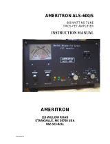
The MIRAGE D-1010-N represents the latest in 430-450 MHz amplifiers. It incorporates
features that make it the most versatile and useful amplifier available today. The D-1010-
N will amplify FM, SSB, and CW signals. It has variable SSB delay, remote Keying,
over-temperature protection, and remote control operation when using the optional RC-1,
Remote.
SPECIFICATIONS
FREQUENCY RANGE....................430-450 MHz
POWER.............................................INPUT: 3-15 watts
OUTPUT: Min of 100 watts with 10W in
MODES.............................................FM, SSB, CW, ATV with modifications
DC POWER ...................................... 13.6 VDC @ 20 amps nominal
FUSE.................................................35 AMP (internally mounted)
IMPENDANCE................................. 50 Ohm input and output
DUTY CYCLE..................................Intermittent-internal overtemp
SIZE...................................................12" x 3" x 5-1/2"
WEIGHT...........................................5 LBS
INSTALLATION
The D-1010-N may be mounted using the brackets supplied. The D-1010-N must have
adequate ventilation for the finned heat-sink. Use #8 or larger wire to connect the D-
1010-N to the battery is recommended. RG-8U, or the equivalent, should be used
between the D-1010-N and the antenna. The antenna should be matched to better than
1.5:1 for best performance. SWR greater than 3:1 may cause damage to the amplifier
voiding and warranty.
FRONT PANEL FUNCTIONS
POWER ON/OFF..............................This switch turns the power amplifier ON and OFF.
SSB/FM.............................................Selects the relay time-delay for the mode of
operation. In either the SSB or FM position, the
amplifier is still biased for linear operation.
LED (Power/On) ...............................This LED will go out if the amplifier overheats. It
will come back on when the amplifier cools.
LED (Tx)...........................................This LED will light during transmitting periods.
REAR PANEL FUNCTIONS

D-1010-N Instruction Manual 430-450 MHz Power Amplifier
2
"RADIO"...........................................This connects to the transmitter or transceiver.
"ANT" ............................................... This connects to the antenna.
RCA Jack ..........................................This connector can be used to ground key the
transmit relay if the input signal is too weak to
activate the RF sensing circuit which normally
handles the function.
6-Pin Remote Connector...................The RC-1 Remote Control Head connects here.
PRECAUTIONS
OUTPUT POWER............................The D-1010-N puts out enough power to cause
heating of the antenna coax. RG-8 or equivalent is
recommended between the amplifier and antenna.
HEAT SINK TEMPERATURE........Along with high power output, comes the
possibility of high heat sink temperatures. The D-
1010-N must be mounted where air can circulate
over the heat sink. The D-1010-N has a built-in
thermostat that will turn it "OFF" at 170 degrees F.
The amplifier will not come back on until the
temperature drops to 140 degrees F.
INPUT POWER................................ Input power should not exceed 15 watts. Higher
power than this may cause failure of the input
transistor. This will VOID ANY WARRANTY.
SSB OPERATION............................The D-1010-N can be overdriven causing the SSB
signal to be distorted. When using the D-1010-N on
SSB, the drive level or the mic gain from the exciter
should be adjusted for best "on the air"
performance.
INTERNAL ADJUSTMENTS
SSB DELAY .....................................This allows the XMT relay delay time to be adjusted
to various lengths. Access to this adjustment is
through the hole in the left side of the cover, behind
the front panel. A small screwdriver can be used to
make the adjustment.
RF ADJUSTMENTS ........................There are no internal adjustments dealing with the
RF amplifier board. Tuning of the RF amplifier is
preset at the factory by our technicians.
FUSE.................................................A 35-amp fuse is located under the cover on the PC
board. Should the fuse "blow," determine the cause
and use the exact type in the unit as a replacement.

D-1010-N Instruction Manual 430-450 MHz Power Amplifier
3
"ATV MOD"..................................... Remove .1 mfd cap and 10 ohm resistor which
crosses over both final power transistors and
connects each base to its collect lead. These
cap/resistor networks are designed to eliminate low
frequency oscillations and will distort ATV signals.
IN CASE OF DIFFICULTY
1. Check for loose antenna or B+ connections.
2 Check SWR of antenna.
3. Look for bad or lossy coax.
TECHNICAL ASSISTANCE
If you have any problem with this unit first check the appropriate section of this manual.
If the manual does not reference your problem or your problem is not solved by reading
the manual you may call MIRAGE at 601-323-8287. You will be best helped if you have
your unit, manual and all information on your station handy so you can answer any
questions the technicians may ask.
You can also send questions by mail to MIRAGE, 921 HWY 25 South, Starkville, MS
39759 or by Fax to 601-323-6551. Send a complete description of your problem, an
explanation of exactly how you are using your unit, and a complete description of your
station.
/