Page is loading ...

AC Immersible Type
Continuous In Air Motors
Frame 210−449 600VAC and less
Installation & Operating Manual
2/15 MN403

Any trademarks used in this manual are the property of their respective owners.
Be sure to check www.baldor.com
for the latest version of this manual in Adobe Acrobat PDF format.

Table of Contents
Table of Contents iMN403
Section 1
General Information 1−1...............................................................................
Overview 1−1.....................................................................................
Limited Warranty 1−1...............................................................................
Safety Notice 1−1..................................................................................
Receiving 1−2.....................................................................................
Handling 1−2......................................................................................
Storage 1−3.......................................................................................
Removal From Storage 1−4.........................................................................
Section 2
Installation & Operation 2−1...........................................................................
Overview 2−1.....................................................................................
Installation 2−1....................................................................................
Grounding 2−3....................................................................................
Operation 2−4.....................................................................................
Section 3
Maintenance & Troubleshooting 3−1....................................................................
General Inspection 3−1.............................................................................
Flood Environment Maintenance 3−1.................................................................
Important 3−1.................................................................................
Disassembly 3−1..............................................................................
Bearing Lubrication Procedure 3−1..............................................................
Seal Carrier Lubrication Procedure
3−2..........................................................
T
roubleshooting Chart 3
−3..........................................................................
Appendix A
Blower Motor A−1.....................................................................................
Overview A−1.....................................................................................
Receiving A−1.....................................................................................
Mounting A−1.....................................................................................
Wiring A−1........................................................................................
Relubrication & Bearings A−1........................................................................
Operation A−2.....................................................................................

Section 1
General Information
ii Table of Contents MN403

Section 1
General Information
General Information 1−1MN403
Overview This manual contains general procedures that apply to BaldorSReliance Motor products. Be sure to read
and understand the Safety Notice statements in this manual. For your protection, do not install, operate
or attempt to perform maintenance procedures until you understand the Warning and Caution
statements.
A Warning statement indicates a possible unsafe condition that can cause harm to personnel.
A Caution statement indicates a condition that can cause damage to equipment.
Important: This instruction manual is not intended to include a comprehensive listing of all details for all
procedures required for installation, operation and maintenance. This manual describes general
guidelines that apply to most of the motor products. If you have a question about a procedure or
are uncertain about any detail, Do Not Proceed. Please contact your Baldor District Office for
more information or clarification.
Before you install, operate or perform maintenance, become familiar with the following:
S NEMA Publication MG-2, Safety Standard for Construction and guide
for Selection, Installation and Use of Electric Motors and Generators.
S The National Electrical Code
S Local codes and Practices
Limited Warranty
www.baldor.com/support/warranty_standard.asp
Safety Notice: This equipment contains high voltage! Electrical shock can cause serious or fatal injury. Only qualified
personnel should attempt installation, operation and maintenance of electrical equipment.
Be sure that you are completely familiar with NEMA publication MG-2, safety standards for construction and
guide for selection, installation and use of electric motors and generators, the National Electrical Code and
local codes and practices. Unsafe installation or use can cause conditions that lead to serious or fatal injury.
Only qualified personnel should attempt the installation, operation and maintenance of this equipment.
WARNING: The Adjustable Speed Controller may apply hazardous voltages to the motor leads after power to
the controller has been turned off. Verify that the controller is incapable of delivering hazardous
voltages and that the voltage at the motor leads is zero before proceeding. Failure to observe this
precaution may result in severe bodily injury or death.
WARNING: Do not touch electrical connections before you first ensure that power has been disconnected.
Electrical shock can cause serious or fatal injury. Only qualified personnel should attempt the
installation, operation and maintenance of this equipment.
WARNING: Be sure the system is properly grounded before applying power. Do not apply AC power before
you ensure that all grounding instructions have been followed. Electrical shock can cause
serious or fatal injury. National Electrical Code and Local codes must be carefully followed.
WARNING: Avoid extended exposure to machinery with high noise levels. Be sure to wear ear protective
devices to reduce harmful effects to your hearing.
WARNING: Surface temperatures of motor enclosures may reach temperatures which can cause discomfort
or injury to personnel accidentally coming into contact with hot surfaces. Protection should be
provided by the user to protect against accidental contact with hot surfaces. Failure to observe
this precaution could result in bodily injury.
WARNING: This equipment may be connected to other machinery that has rotating parts or parts that are
driven by this equipment. Improper use can cause serious or fatal injury. Only qualified
personnel should attempt to install operate or maintain this equipment.
WARNING: Do not by-pass or disable protective devices or safety guards. Safety features are designed to
prevent damage to personnel or equipment. These devices can only provide protection if they
remain operative.
WARNING: Avoid the use of automatic reset devices if the automatic restarting of equipment can be
hazardous to personnel or equipment.
WARNING: Be sure the load is properly coupled to the motor shaft before applying power. The shaft key
must be fully captive by the load device. Improper coupling can cause harm to personnel or
equipment if the load decouples from the shaft during operation.
WARNING: Use proper care and procedures that are safe during handling, lifting, installing, operating and
maintaining operations. Improper methods may cause muscle strain or other harm.

Section 1
General Information
1−2 General Information MN403
Safety Notice Continued
WARNING: Pacemaker danger − Magnetic and electromagnetic fields in the vicinity of current carrying
carrying conductors and permanent magnet motors can result result in a serious health hazard to
persons with cardiac pacemakers, metal implants, and hearing aids. To avoid risk, stay way from
the area surrounding a permanent magnet motor.
WARNING: Incorrect motor rotation direction can cause serious or fatal injury or equipment damage. Be sure
to verify motor rotation direction before coupling the load to the motor shaft.
WARNING: Do not use non UL/CSA listed explosion proof motors in the presence of flammable or
combustible vapors or dust. These motors are not designed for atmospheric conditions that
require explosion proof operation.
Caution: Do not lift the motor and its driven load by the motor lifting hardware. The motor lifting hardware
is adequate for lifting only the motor. Disconnect the load (gears, pumps, compressors, or other
driven equipment) from the motor shaft before lifting the motor.
WARNING: Guards must be installed for rotating parts such as couplings, pulleys, external fans, and unused
shaft extensions, should be permanently guarded to prevent accidental contact by personnel.
Accidental contact with body parts or clothing can cause serious or fatal injury.
WARNING: Thermostat contacts automatically reset when the motor has slightly cooled down. To prevent
injury or damage, the control circuit should be designed so that automatic starting of the motor is
not possible when the thermostat resets.
Caution: To prevent equipment damage, be sure that the electrical service is not capable of delivering more
than the maximum motor rated amps listed on the rating plate.
Caution: If a HI POT test (High Potential Insulation test) must be performed, follow the precautions and
procedure in NEMA MG1 and MG2 standards to avoid equipment damage.
Caution: Never raise or lower the motor/pump by the power cords. Use motor lift provisions. Failure to lift
this motor properly may seriously damage the lead connections and water seals and seriously
damage the motor.
Caution: Never mix or use incompatible lubricants. Watch for signs of lubricant incompatibility. Failure to
use compatible lubricants could result in damage to motor.
Caution: Lift the motor using Lift Provisions only. Disconnect the load from the motor before lifting. Use a
spreader bar to evenly distribute lift force of motor. Angle of lift rope (no spreader bar) should not
exceed 45 from vertical, excessive lift angle can damage motor.
If you have any questions or are uncertain about any statement or procedure, or if you require additional
information please contact your Baldor District Office or an Authorized Baldor Service Center.
Receiving
Each BaldorSReliance Motor is thoroughly tested at the factory and carefully packaged for shipment.
When you receive your motor, there are several things you should do immediately.
1. Observe the condition of the shipping container and report any damage immediately to the
commercial carrier that delivered your motor. The carrier is responsible for all damage.
2. Verify that the part number of the motor you received is the same as the part number listed on your
purchase order and please contact your Baldor District Office if there is a problem.

General Information 1−3MN403
Storage
Storage requirements for motors and generators that will not be placed in service for at least six months
from date of shipment.
Improper motor storage will result in seriously reduced reliability and failure. An electric motor that does
not experience regular usage while being exposed to normally humid atmospheric conditions is likely to
develop rust in the bearings or rust particles from surrounding surfaces may contaminate the bearings.
The electrical insulation may absorb an excessive amount of moisture leading to the motor winding
failure.
A wooden crate “shell” should be constructed to secure the motor during storage. This is similar to an
export box but the sides & top must be secured to the wooden base with lag bolts (not nailed as export
boxes are) to allow opening and reclosing many times without damage to the “shell”.
Minimum resistance of motor winding insulation is 5 Meg ohms or the calculated minimum, which ever is
greater. Minimum resistance is calculated as follows: Rm = kV + 1
where: (Rm is minimum resistance to ground in Meg−Ohms and
kV is rated nameplate voltage defined as Kilo−Volts.)
Example: For a 480VAC rated motor Rm =1.48 meg−ohms (use 5 M).
For a 4160VAC rated motor Rm = 5.16 meg−ohms.
Preparation for Storage
1. Some motors have a shipping brace attached to the shaft to prevent damage during transportation.
The shipping brace, if provided, must be removed and stored for future use. The brace must be
reinstalled to hold the shaft firmly in place against the bearing before the motor is moved.
2. Store in a clean, dry, protected warehouse where control is maintained as follows:
a. Shock or vibration must not exceed 2 mils maximum at 60 hertz, to prevent the bearings from
brinelling. If shock or vibration exceeds this limit vibration isolation pads must be used.
b. Storage temperatures of 10C (50F) to 49C (120F) must be maintained.
c. Relative humidity must not exceed 60%.
d. Motor space heaters (when present) are to be connected and energized whenever there is a
possibility that the storage ambient conditions will reach the dew point.
Note: Remove motor from containers when heaters are energized, reprotect if necessary.
3. Measure and record the resistance of the winding insulation (dielectric withstand) every 30 days of
storage.
a. If motor insulation resistance decreases below the minimum resistance, contact your Baldor
District office.
b. Place new desiccant inside the vapor bag and re−seal by taping it closed.
c. If a zipper−closing type bag is used instead of the heat−sealed type bag, zip the bag closed
instead of taping it. Be sure to place new desiccant inside bag after each monthly inspection.
d. Place the shell over the motor and secure with lag bolts.
4. Where motors are mounted to machinery, the mounting must be such that the drains and breathers
are fully operable and are at the lowest point of the motor. Vertical motors must be stored in the
vertical position. Storage environment must be maintained as stated in step 2.
5. Motors with anti−friction bearings are to be greased at the time of going into extended storage and the
motor shafts are to be rotated manually every 3 months and greased every 6 months in accordance
with Section 3 of this manual.
6. Coat all external machined surfaces with a rust preventing material.
An acceptable product for this purpose is Exxon Rust Ban # 392 or equivalent.

1−4 General Information MN403
Immersible Motor, Horizontal or Vertical
Before storage, the following procedure must be performed.
1. Remove the grease drain plug, if supplied, (opposite the grease fitting) on the bottom of each bracket
prior to lubricating the motor.
2. The motor with regreaseable bearing must be greased as instructed in Section 3 of this manual.
3. Replace the grease drain plug after greasing.
4. The motor shaft must be rotated a minimum of 15 times after greasing.
5. Motor Shafts are to be rotated at least 15 revolutions manually every 3 months and additional grease
added every nine months (see Section 3) to each bearing.
6. Bearings are to be greased at the time of removal from storage.
Removal From Storage
1. Remove all packing material.
2. Measure and record the electrical resistance of the winding insulation resistance meter at the time of
removal from storage. The insulation resistance must not be less than 50% from the initial reading
recorded when the motor was placed into storage. A decrease in resistance indicates moisture in the
windings and necessitates electrical or mechanical drying before the motor can be placed into
service. If resistance is low, contact your Baldor District office.
3. Regrease the bearings as instructed in Section 3 of this manual.
4. Reinstall the original shipping brace if motor is to be moved. This will hold the shaft firmly against the
bearing and prevent damage during movement.

Section 2
Installation & Operation
Installation & Operation 2−1MN403
Overview
Installation should conform to the National Electrical Code as well as local codes and practices. In
addition, the following devices must be connected, as described in this Section:
1. Thermal protectors are provided and must be connected.
Leads are marked P1 and P2 for thermostats.
2. Space heaters are provided and must be connected when the motor is not in service.
Leads are marked H1 and H2.
3. An optional moisture detector (if provided) must be connected.
The moisture detector is located in the motor housing.
Leads are marked 1TD1, 1TD2, 1TD3, 1TD4.
4. An Auxiliary blower motor is provided for cooling. A float switch must be supplied by the pump OEM
to remove power from the blower motor in the event the motor becomes immersed.
5. The motor cable assembly has three power leads (T1, T2, and T3), two ground leads, two thermal
leads, two space heaters leads and optional moisture detector leads. Standard cable length is 25 feet.
Caution: Never raise or lower the motor/pump by the power cords. Use motor lift provisions. Failure to lift
this motor properly may seriously damage the lead connections and water seals and seriously
damage the motor.
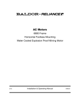
Caution: Lift the motor using Lift Provisions only. Disconnect the load from the motor before lifting. Use a
spreader bar to evenly distribute lift force of motor. Angle of lift rope (no spreader bar) should not
exceed 45 from vertical, excessive lift angle can damage motor.
Note: Motor weight is stated on the motor name plate.
Figure 2-1
Spreader
Bar
Preferred Lift
Method
Lift Eye
Pump
Motor
Level 1
Level 2
Below Level 1
Maximum depth
is 30 ft.
WARNING: Do not touch electrical connections before you first ensure that power has been disconnected.
Electrical shock can cause serious or fatal injury. Only qualified personnel should attempt the
installation, operation and maintenance of this equipment.
WARNING: The Adjustable Speed Controller may apply hazardous voltages to the motor leads after power to
the controller has been turned off. Verify that the controller is incapable of delivering hazardous
voltages and that the voltage at the motor leads is zero before proceeding. Failure to observe this
precaution may result in severe bodily injury or death.
Installation
When the immersible motor leaves the factory it is ready for installation. No adjustment, venting or oil
filling is required. When mounting the motor it is essential that motor and driven unit be rigidly supported
in correct alignment. All motors and generators covered by this publication should be installed and
protected in accordance with the National Electric Code.
The user must select a motor starter and over current protection suitable for this motor and its application.
Consult motor starter application data as well as National Electric Code and/or other applicable local
codes.

2−2 Installation & Operation MN403
Installation Procedure
To prevent damage to the motor, do not use force to drive pump on (drive impeller onto motor shaft) or to
remove pump from motor shaft.
1. Turn off and lockout all power and verify the voltage at the motor starter connectors are zero.
2. Connect the motor power leads “T1”, “T2”, “T3” and “G” (ground C/Box) to the connectors in the
motor starter, see Figure 2-2.
Figure 2-2 AC Motor Connection Diagram
(Optional)
(Optional)

Installation & Operation 2−3MN403
3. Three Phase Motors ONLY.
a. Turn off and lockout all power and verify the voltage at the motor starter connectors are zero.
b. Be sure the motor shaft is disconnected from the load and will not cause mechanical rotation of
the motor shaft.
c. Remove all unused shaft keys and loose rotating parts to prevent them from flying off.
d. Momentarily apply power and check the direction of rotation of the motor shaft.
Motors are designed for bi−directional shaft rotation. When voltages in an A−B−C phase
sequence are applied to leads U/T1, V/T2, W/T3 clockwise shaft rotation facing the opposite drive
end will result. If shaft rotation is incorrect, change the direction of rotation as follows:
i. Turn off and lockout all power and verify that the voltage at the motor leads is zero.
ii. Reverse any two of three motor power leads at the motor starter.
iii. Restore power and verify correct rotation.
iv. Turn off and lockout all power and verify that the voltage at the motor leads is zero.
4. Connect the two Thermal Leads “P1” & “P2” at the motor starter as shown in Figure 2-2.
5. Connect the two Heater Leads “H1” & “H2” at the motor starter as shown in Figure 2-2.
6. Connect the “G” (ground C/Box) lead at the motor starter as shown in Figure 2-2
(for Cable Cap Exit Conduit Box only).
7. If optional “Moisture Sensor” is present, do the following:
a. Connect the Moisture Sensor “1TD1”, “2TD2”, “3TD3” and “4TD4” leads at the motor starter as
shown in Figure 2-2.
b. Connect the Moisture Sensor “G” (ground C/Box) lead at the motor starter as shown in Figure
2-2 (for Cable Cap Exit Conduit Box only).
Caution: Never raise or lower the motor/pump by the power cords. Use motor lift provisions. Failure to lift
this motor properly may seriously damage the lead connections and water seals and seriously
damage the motor.
Caution: Lift the motor using Lift Provisions only. Disconnect the load from the motor before lifting. Use a
spreader bar to evenly distribute lift force of motor. Angle of lift rope (no spreader bar) should not
exceed 45 from vertical, excessive lift angle can damage motor.
8. Use spreader bar and lifting eyes (see Figure 2-1) to lower the motor to the mounting foundation.
Be sure that motor wires are not damaged (contact with metal objects etc.)
9. Follow pump manufacturer’s instructions and mount the pump onto the motor shaft.
10. Secure the pump case to the motor flange maintaining proper alignment.
11. Attach drain piping to pump.
12. Mount the motor on a foundation sufficiently rigid to prevent vibration.
After careful alignment, bolt motor securely in place.
13. Set control parameter values (if applicable) according to motor nameplate values.
Grounding In the USA consult the National Electrical Code, Article 430 for information on grounding of motors and
generators, and Article 250 for general information on grounding. In making the ground connection, the
installer should make certain that there is a solid and permanent metallic connection between the ground
point, the motor or generator terminal housing, and the motor or generator frame. In non−USA locations
consult the appropriate national or local code applicable.

2−4 Installation & Operation MN403
WARNING: Surface temperatures of motor enclosures may reach temperatures which can cause discomfort
or injury to personnel accidentally coming into contact with hot surfaces. Protection should be
provided by the user to protect against accidental contact with hot surfaces. Failure to observe
this precaution could result in bodily injury.
WARNING: Do not touch electrical connections before you first ensure that power has been disconnected.
Electrical shock can cause serious or fatal injury. Only qualified personnel should attempt the
installation, operation and maintenance of this equipment.
WARNING: Disconnect all electrical power from the motor windings and accessory devices before
disassembly of the motor. Electrical shock can cause serious or fatal injury.
WARNING: Be sure the system is properly grounded before applying power. Do not apply AC power before
you ensure that all grounding instructions have been followed. Electrical shock can cause
serious or fatal injury. National Electrical Code and Local codes must be carefully followed.
Operation Verify the installation is complete, all connections are made, and the motor and load are properly aligned
and mounted. Apply power to the motor and observe the motor during operation.
During operation, observe the motors performance.
S It should run smoothly with little noise.
S Observe the condition of the motor cable and all connections.
Damaged insulation or damaged connection points must be repaired at once.
Motor operation may stop for one of the following trip conditions:
1. If moisture infiltrates the motor, the optional moisture detector circuit will activate (if present).
2. If the motor overheats, the Thermal Protection circuit will activate.
Motors supplied with thermal protectors are furnished with automatic reset type to protect against
destructive overheating. If the protector trips, proceed as follows:
For Automatic Reset Type
This type will reset itself when the motor cools sufficiently.
If the thermal protector continues to trip, some abnormal condition exists.
This condition must be corrected before motor will operate normally.
3. Other condition detected by motor starter (over current, over voltage, etc. if equipped)
Unbalanced voltage or single−phase operation of poly phase motor may cause excessive heating and
ultimate failure. Only a slight unbalance of voltage applied to a poly phase motor will cause large
unbalanced currents and resultant overheating. Periodic checks of phase voltage, frequency and power
consumption of a motor (measured at the motor starter) while in operation are recommended; such
checks assure the correctness of frequency and voltage applied to the motor and yield an indication of the
load offered by the apparatus which the motor drives.
Comparisons of this data with previous no load and full−load power demands will give an indication of the
performance of the complete machine. Any serious deviations should be investigated and corrected.
Should the Cable Cap assembly be damaged or the integrity of the encapsulation be in question, it is
required that a replacement Cable Cap assembly be ordered from Baldor, contact your Baldor District
Office. Renewal instructions will be provided with the replacement parts.

Section 3
Maintenance & Troubleshooting
Maintenance & Troubleshooting 3--1MN403
General Inspection
Inspect the motor a t regular intervals, approximately e very 500 hours of operation or every 3
months, whichever occurs first. Keep the motor clean and the ventilation openings clear.
The following steps should be performed at each inspection:
WARNING: Do not touch electrical connections before you first ensure that power has been disconnected.
Electrical shock can cause serious or fatal injury. Only qualified personnel should attempt the
installation, operation and maintenance of this equipment.
Flood Environment Maintenance
Immersible motors are designed to tolerate operation for 14 days when submerged.
The motor must never be submerged more than 30 feet. When a motor becomes submerged, the
external OEM provided float switch (not provided by Baldor) must disconnect power to the external
blower motor. Whenever this submerged operation occurs, the motor is then cooled by the liquid.
These maintenance repairs are to be performed by a Baldor approved repair facility.
The costs for this maintenance is the customers responsibility and is necessary to continue the
warranty.
Important If motor has run in a flood environment, it must be disassembled and the following maintenance
performed.
1. Blower motor, see Appendix A.
2. Inspect bearings.
a. If the bearings are dry, regrease per bearing lubrication procedure.
b. If the bearings are wet, replace bearings and regrease per bearing lubrication procedure.
3. Replace O--rings on brackets.
4. Replace seals in carrier.
5. Completely fill seal carrier with grease per seal carrier lubrication procedure.
Disassembly If it becomes necessary to disassemble this motor, care should be taken not to damage the stator
windings as the insulation may be injured by improper or rough handling.
Precautions to keep bearings clean should be exercised.
1. Remove bearing cap screws before removing end shield screws.
Marking end shields relative to position on frame will make reassembly easier.
2. Bearings should not be removed unless they are to be replaced.
3. If it is necessary to open the conduit box,refer to Figure 2--2 for proper connections.
4. The O--ring should be replaced when reassembled.
Bearing Lubrication Procedure
This motor has been properly lubricated at the time of manufacture and it is not necessary to lubricate at
time of installation. If motor has been in storage for a period of six months or more, lubricate before
starting. Lubrication of anti friction bearings and seal carrier should be done as a part of a planned
maintenance schedule. The recommended lubrication interval should be used as a guide to establish this
schedule.
Cleanliness is important in lubrication. Any grease used to lubricate anti-- friction bearings should be fresh
and free from contamination. Similarly, care should be taken to properly clean the grease inlet area of the
motor to prevent grease contamination.
Recommended Lubricant For Bearings
Use lubricant stated on motor nameplate. If lubricant is not specified, for motors operating in ambient
temperatures from -- 25Cto+65C, use the following:
Chevron Black Pearl EP N--2.

3−2 Maintenance & Troubleshooting MN403
Table 3-1 Recommended Lubricant Volume
Frame Size Lubricant Amount
210-215 0.5 cu. In.
254-286 1.0 cu. In.
324-365 1.5 cu. In.
404-449 2.5 cu. In.
Lubrication Frequency
Baldor anti−friction bearings may be lubricated with the motor running or stationary, however,
stationary with the motor warm is preferred.
1. Locate the grease inlet, clean the area and replace the pipe plug with a grease fitting.
2. The motor is equipped with a grease drain plug. Remove the plug and loosen any hardened grease
that may block the drain.
3. Add recommended lubricant volume (Table 3-1) using a hand operated grease gun.
4. Run the motor for two hours.
5. Replace the grease drain plug.
6. Replace the pipe plug in grease inlet.
Caution: Never mix or use incompatible lubricants. Watch for signs of lubricant incompatibility. Failure to
use compatible lubricants could result in damage to motor.
Special Applications:
For high temperature applications, contact your Baldor District Office for recommended lubricants.
Mixing lubricants is not recommended due to the possibility of incompatibility. If it is desired to change
lubricant without motor disassembly, follow instructions for lubrication and repeat lubrication a second
time after 100 hours of service.
Watch for signs of lubricant incompatibility visible from the grease relief area. Incompatible lubricant
could result in damage to equipment.
Seal Carrier Lubrication Procedure
Seal Carrier should be greased every 6 months.
1. Remove plugs located on seal carrier.
2. Add Chevron Black Pearl EP N−2 grease until new grease purges out the drain.
3. Replace other plug.
Lubricant for Seal Carrier Chevron Black Pearl EP N−2. Substitutions are not recommended.

Section 1
General Information
Maintenance & Troubleshooting 3--3MN403
Table 3-2
Troubleshooting Chart
Symptom Possible Causes Possible Solutions
Motor will not start Usually caused by line trouble, such
as, single phasing at the starter.
Check source of power. Check overloads, fuses,
controls, etc.
Excessive humming High Voltage. Check input line connections.
Eccentric air gap. Have motor serviced at local Baldor service center.
MotorOverHeating Overload. Compare actual amps
(measured) with nameplate rating.
Locate and remove source of excessive friction in
motor or load.
Reduce load or replace with motor of greater capacity.
Single Phasing. Check current at all phases (should be approximately
equal) to isolate and correct the problem.
Improper ventilation. Check external cooling fan to be sure air is moving
properly across cooling fins.
Excessive dirt
build up on motor. Clean motor.
Unbalanced voltage. Check voltage at all phases (should be approximately
equal) to isolate and correct the problem.
Rotor rubbing on stator. Check air gap clearance and bearings.
Tighten
Thru Bolts”.
Over voltage or under voltage. Check input voltage at each phase to motor.
Open stator winding. Check stator resistance at all three phases for
balance.
Grounded winding. Perform dielectric test and repair as required.
Improper connections. Inspect all electrical connections for proper
termination, clearance, mechanical strength and
electrical continuity. Refer to motor lead connection
diagram.
Bearing Over Heating Misalignment. Check and align motor and driven equipment.
Excessive belt tension. Reduce belt tension to proper point for load.
Excessive end thrust. Reduce the end thrust from driven machine.
Excessive grease in bearing. Remove grease until cavity is approximately
3
/
4
filled.
Insufficient grease in bearing. Add grease until cavity is approximately
3
/
4
filled.
Dirt in bearing. Clean bearing cavity and bearing. Repack with correct
grease until cavity is approximately
3
/
4
filled.
Vibration Misalignment. Check and align motor and driven equipment.
Rubbing between rotating parts and
stationary parts.
Isolate and eliminate cause of rubbing.
Rotor out of balance. Have rotor balance checked and repaired at your
Baldor Service Center.
Resonance. Tune system or contact your Baldor Service Center
for assistance.
Noise Foreign material in air gap or
ventilation openings.
Remove rotor and foreign material. Reinstall rotor.
Check insulation integrity. Clean ventilation openings.
Growling or whining Bad bearing. Replace bearing. Clean all grease from cavity and
new bearing. Repack with correct grease until cavity
is approximately
3
/
4
filled.

3−4 Maintenance & Troubleshooting MN403
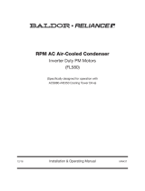
Figure 3-1 Cross Section Diagram
1
2
3
4
5
6
7
8
9
10
11
12
13
14
15
16
17
18
19
20
21
22
23
24
25
Frame
Stator
Rotor
Drive End bracket (DE)
Opposite Drive End bracket (ODE)
Shaft
Back end inner cap
Drive End Bearing
Opposite Drive End bracket plug
Back end bracket bolts
Fan cover
Outer Fan
Fan Clamp
Drip Cover
Drip Cover Bolts
Seal Carriage
Opposite Drive End bearing
Blower Cable Entry
Lip seals, Tandem arrangement
Lifting Plates
Conduit Box/Cable Cap Assembly
Blower motor
O ring, ODE bracket
O ring, DE bracket
O ring, Seal Carrier
Motors are regreaseable.
Grease inlet and outlet not shown
Note: 210TY Frame TENV.

Appendix A
Blower Motor
Blower Motor A--1MN403
Overview Blower motor is a Fractional or Integral Horsepower Poly phase AC motor (does not apply to 210TY).
Baldor blower motors are provided in two configurations; Washdown or Immersible.
The washdown design is standard and the immersible design is available as an option.
When the primary motor is submerged, a float switch (not provided) disengages the blower motor and the
primary motor is cooled by the liquid.
If this occurs and the blower motor was also submerged, the blower motor must be serviced.
The costs for this maintenance is the customers responsibility and is necessary to continue the warranty.
Washdown Blower Motor
Washdown blower motors should be replaced.
Immersible Blower Motor
Immersible blower motors should be sent to a Baldor approved repair facility for inspection and rework.
Required repairs may include replacement of bearings and seals if necessary.
Check with your local Baldor district office to verify which design was provided.
Receiving
Each BaldorSReliance Motor is thoroughly tested at the factory and carefully packaged for shipment.
When you receive your motor, there are several things you should do immediately.
1. Observe the condition of the shipping container and report any damage immediately to the
commercial carrier that delivered your motor. The carrier is responsible for all damage.
2. Verify that the part number of the motor you received is the same as the part number listed on your
purchase order and please contact your Baldor District Office if there is a problem.
Mounting Mount the motor on a foundation sufficiently rigid to prevent vibration.
After careful alignment, bolt motor securely in place.
Wiring Check nameplate data on motor before installing to ensure correct rating and that the available power
supply is compatible. If in doubt, check local power company. Fuses, wires, thermal cutouts and other
protective devices should be the proper size and rating to safely carry the load and to interrupt the circuit
on overloads. Thermal devices, when installed, are of proper size to provide the required protection.
All motors contain wiring instructions either as a label on the inside of the conduit box cover or by
separate sheet or tag. All motors should be installed in accordance with the National Electric Code and
local requirements. Check leads or terminals with connection diagrams or label so the proper connections
to the incoming power leads are made.
Rotation
Refer to notation on wiring diagram for method of changing rotation.
Ambient Temperature
Each motor nameplate states a maximum ambient temperature rating. Motors should not be operated at
ambient temperatures in excess of their rating.
Relubrication &
Bearings
Ball Bearings
The ball bearing has deep grooved, double shielded bearings with sufficient lubricant packed into the
bearings by the manufacturer for ”life Lubrication”. The initial lubricant is supplemented by a supply
packed into larger reservoirs in the end shield at time of assembly. (No grease fittings are provided).

A−2 Blower Motor MN403
Operation Verify the installation is complete, all connections are made, and the motor and load are properly aligned
and mounted. Apply power to the motor and observe the motor during operation.
During operation, observe the motors performance.
S It should run smoothly with little noise.
S Observe the condition of the motor cable and all connections.
Damaged insulation or damaged connection points must be repaired at once.
Motor operation may stop for one of the following trip conditions:
1. If moisture infiltrates the motor, the moisture detector circuit will activate.
2. If the motor overheats, the Thermal Protection circuit will activate.
Motors supplied with thermal protectors are furnished with either a manual or automatic reset type to
protect against destructive overheating. If the protector trips, proceed as follows:
For Manual Reset Type
a. Wait two minutes.
b. Push in reset plunger until it catches.
For Automatic Reset Type
This type will reset itself when the motor cools sufficiently.
If the thermal protector continues to trip, some abnormal condition exists.
This condition must be corrected before motor will operate normally.
Troubleshooting
If trouble develops during motor operation, be sure that:
1. The bearings are in normal condition and have been properly lubricated with a high grade, ball
bearing lubricant, free of dirt or grit. (If dirt enters bearing, flush and relubricate.)
2. Mechanical adjustment is correct to allow free rotation of moving parts of motor and drive.
3. All bolts and nuts are properly tightened.
4. Motor instructions have been carefully followed.
5. Full rated voltage is available in all phases at the motor terminals.
6. That the line voltage, frequency and phase correspond to the values stamped on the nameplate.
7. That all connections and contacts are properly made in all circuits between motor and line, and
between motor and control.


2010 Baldor Electric Company
MN403
All rights reserved. Printed in USA
2/15
P.O. Box 2400 Fort Smith, AR 72902--2400 (479) 646--4711 Fax (479) 648--5792
www.baldor.com
MN403-0215
/