Fanimation LP8359L Owner's manual
- Category
- Household fans
- Type
- Owner's manual

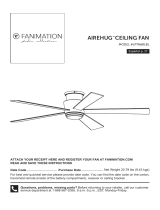
Date Code
Purchase Date
ATTACH YOUR RECEIPT HERE AND REGISTER YOUR FAN AT FANIMATION.COM
READ AND SAVE THESE INSTRUCTIONS
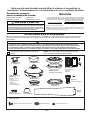
Net Weight
22.34 lbs (10.13 kg)
Questions, problems, missing parts? Before returning to your retailer, call our customer
service department at 1-888-567-2055, 8 a.m.-5 p.m., EST, Monday-Friday.
For best and quickest service please provide date code. You can find the date code on the carton,
hand-held remote (inside of the battery compartment), receiver or top of fan housing.
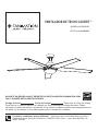
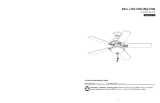
ITEM #0588962
Español p. 23
MODEL #LP8359LAZ
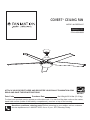
COVERT
™
CEILING FAN

Important Safety Instructions
WARNING: To avoid fire, shock and serious personal injury, follow these instructions.
1. Read your owner’s manual and safety information before installing your new fan. Review the accompanying assembly
diagrams.
2. Before servicing or cleaning unit, switch power off at service panel and lock service panel disconnecting means to prevent
power from being switched on accidentally. When the service disconnecting means cannot be locked, securely fasten a
warning device, such as a tag, to the service panel.
3. Be careful of the fan and blades when cleaning, painting, or working near the fan. Always turn off the power to the ceiling
fan before servicing.
4. Do not insert anything into the fan blades while the fan is operating.
A
dditional Safety Instructions
1. To avoid possible shock, be sure electricity is turned off at the fuse box before wiring, and do not operate fan without
blades.
2. All wiring and installation procedures must satisfy National Electrical Codes (ANSI/ NFPA 70) and Local Codes. The
ceiling fan must be grounded as a precaution against possible electrical shock. Electrical installation should be made or
approved by a licensed electrician.
3. The fan base must be securely mounted and capable of reliably supporting at least 35 lbs. (fan and accessories not to
exceed 35 lbs. or 15.88 kgs.). See page 5 of owner’s manual for support requirements. Consult a qualified electrician if in
doubt.
4. The fan must be mounted with the fan blades at least 7 feet from the floor to prevent accidental contact with the fan blades.
5. Follow the recommended instructions for the proper method of wiring your ceiling fan. If you do not have adequate
electrical knowledge or experience, have your fan installed by licensed electrician.
6. Suitable for use with solid-state speed controls.
WARNING:
WARNING:
Chemical Burn Hazard. Keep batteries away from children.
TO REDUCE THE RISK OF ELECTRIC SHOCK, THIS FAN MUST BE INSTALLED WITH A GENERAL USE,
ISOLATING WALL CONTROL/SWITCH.
WARNING
:
This product is designed to use only those parts supplied with this product and/or accessories designated
specifically for use with this product. Using parts and/or accessories not designated for use with this product could result in
personal injury or property damage.
WARNING
:
To reduce the risk of personal injury, do not bend the blade bracket (flange or blade holder) when installing the
WARNING
:
Mount to an outlet box marked acceptable for fan support of 15.9 kg (35 lbs) or Less.
brackets, balancing the blades, or cleaning the fan. Do not insert foreign objects in between rotating fan blades.
This device complies with Part 15 of the FCC Rules. Operation is subject to the following two conditions:
(1) This device may not cause harmful interference, and (2) this device must accept any interference received, including
interference that may cause undesired operation. Please note that changes or modifications not expressly approved by the
party responsible for compliance could void the user's authority to operate the equipment.
Note: This equipment has been tested and found to comply with the limits for Class B digital device, pursuant to part 15 of the
FCC Rules. These limits are designed to provide reasonable protection against harmful interference in a residential installation.
This equipment generates, uses and can radiate radio frequency energy and, if not installed and used in accordance with the
instructions, may cause harmful interference to radio or television reception, which can be determined by turning the
equipment off and on, the user is encouraged to try to correct the interference by one or more of the following measures:
- Reorient or relocate the receiving antenna.
- Increase the separation between the equipment and the receiver.
- Connect the equipment into an outlet on a circuit different from that to which the receiver is connected.
Consult the dealer or an experienced radio/TV technician for help.
5. The appliance is not intended for use by young children or infirm persons without supervision. Young children should be
supervised to ensure that they do not play with the appliance.
9. For supply connections, if the conductor of a fan is identified as a grounded conductor, then it should be connected to a
is swallowed or enters the body, it can cause severe internal burns and can lead to death in as little as 2 hours. Always
completely secure the battery compartment. If the battery compartment does not close securely, stop using the remote control
of the product, remove the batteries, and keep it away from children. If you think batteries might have been swallowed or placed
inside any part of the body, seek immediate medical attention.
- The cells shall be disposed of properly, including keeping them away from children.
- Even used cells may cause injury.
grounded conductor power supply. If the conductor of a fan is identified as an ungrounded conductor, then it should be
connected to an ungrounded conductor power supply. If the conductor of a fan is identified for equipment grounding, then it
should be connected to an equipment-grounding conductor.
WARNING: Do not operate this fan with a variable (Rheostat) wall controller or dimmer switch. Doing so could result in damage
to the ceiling fan's remote control unit.
7. This fan is to be used in dry and damp locations.
8. Use only with light kits marked suitable for use in damp locations.
10. The remote control of this product contains lithium button/coin cell batteries. If a new or used lithium button/coin cell battery

4. If any other part of your light kit fails at any time within five years after original purchase, due to a defect in materials or
workmanship, we will repair, or replace, at our option, the defective part free of charge for parts and labor performed at our
national service center.
LIMITED LIFETIME WARRANTY
1. LIMITED LIFETIME MOTOR WARRANTY - If any part of your fan motor fails, due to a defect in materials or workmanship
during the lifetime of the original purchaser, Fanimation will provide the replacement part free of charge, when the defective
fan is returned to our national service center. Proof of purchase is required. Customer shall be responsible for all costs
incurred in the removal or reinstallation and shipping of the product for repairs or replacement.
2. ONE YEAR MOTOR LABOR WARRANTY - If your fan motor fails at any time within one year from the original purchase, due
to defects in materials or workmanship, labor to repair the motor will be provided free of charge at our national service
center. Purchaser will be responsible for labor charges after this one-year period. Customer shall be responsible for all
costs incurred in the removal or reinstallation and shipping of the product for repairs or replacement.
3. If any other part of your fan fails at any time within three years after original purchase, due to a defect in materials or
workmanship, we will repair, or replace, at our option, the defective part free of charge for parts and labor performed at our
national service center.
5. Because of varying climate conditions, this warranty does not cover changes in the finish, including rusting, pitting,
corroding, tarnishing, or peeling.
6. This warranty is void and does not apply to damage from improper installation, neglect, accident, misuse, exposure to
extremes of heat or humidity, or as a result of any modification to the original product.
Extends to the original purchaser of a Fanimation fan from an authorized Fanimation dealer/retailer only
7. All costs of removal and reinstallation of the fan are the sole responsibility of the owner of the fan and not the store that
sold the fan or Fanimation.
8. Fanimation reserves the right to modify or discontinue any product at any time and may substitute any part under this
warranty.
10. It is understood that any repair or replacement is the exclusive remedy available from Fanimation. There is no other
expressed or implied warranty. Fanimation hereby disclaims any and all implied warranties, including, but not limited to
those of merchantability and fitness for a particular purpose to the extent permitted by law. Some states do not allow
limitations on implied warranties. Fanimation will not be liable for incidental, consequential, or special damages arising out
of or in conjunction with product use or performance, except as may otherwise be accorded by law. This warranty gives you
special legal rights and you may also have other rights that vary from state to state.
11.A certain amount of wobble is normal and should not be considered a problem or a defect.
9. Under no circumstances may a fan be returned without prior authorization from Fanimation. The receipt of purchase must
accompany authorized returns and must be sent freight prepaid to Fanimation. The fan to be returned must be properly
packed to avoid damage in transit; Fanimation will not be responsible for any damage resulting from improper packaging.
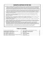
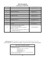
Table of Contents
Unpacking Instructions . . . . . . . . . . . . . . . . . . . . . . . . . . . . . .
Energy Efficient Use of Ceiling Fans . . . . . . . . . . . . . . . . . . .
Electrical and Structural Requirements. . . . . . . . . . . . . . . . .
How to Assemble Your Ceiling Fan Blades . . . . . . . . . . . . .
How to Assemble Your Ceiling Fan . . . . . . . . . . . . . . . . . . . .
How to Hang Your Ceiling Fan . . . . . . . . . . . . . . . . . . . . . . .
How to Wire Your Ceiling Fan . . . . . . . . . . . . . . . . . . . . . . .
How to Install Your Canopy Housing . . . . . . . . . . . . . . . . . .
4
5
5
7
8
10
11
13
How to Assemble Your Light Kit Assembly or Cap. . . . . . . .
How to Operate Your Ceiling Fan . . . . . . . . . . . . . . . . . . . . . .
How to Install Your Remote Control . . . . . . . . . . . . . . . . . . .
Maintenance . . . . . . . . . . . . . . . . . . . . . . . . . . . . . . . . . . . . . . .
How to Clean Your Ceiling Fan Blades . . . . . . . . . . . . . . . . .
Troubleshooting . . . . . . . . . . . . . . . . . . . . . . . . . . . . . . . . . . . .
Parts List . . . . . . . . . . . . . . . . . . . . . . . . . . . . . . . . . . . . . . . . . .
Exploded-View Illustration . . . . . . . . . . . . . . . . . . . . . . . . . . . .
14
15
18
18
18
19
20
21

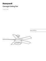
Ceiling Canopy (1)
Hanger Bracket
Assembly (1)
Motor Assembly (1)
Steel Cap (1)
Blade Set (1)
LED Assembly (1)
Motor Coupling
Cover Assembly (1)
Canopy Screw
Cover Assembly (1)
Light Kit Assembly
with Glass (1)
Receiver (1)
Wire Connectors (9)
Hand-held Remote (1)
Wall Plate (1)
Screws (2)
Batteries (2)
Downrod/Hanger Ball
Assembly (1)
– Downrod (1)
– Hanger Ball (1)
– Clevis Pin (1)
– Hairpin Clip (1)
– Set Screw (1)
– Pin (1)
Hardware Bags
Wire Connectors (4)
#8-32 Washer Head Screws (16)
Fiber Washers (16)
4
This manual is designed to make it as easy as possible for you to assemble,
install, operate and maintain your ceiling fan
Tools Needed for Assembly
ne hillips head screwdriver
One stepladder
nstalled ire ength
ire i e
Before assembling your ceiling fan, refer to section
on proper method of wiring your fan (page 11). If you
feel you do not have enough wiring knowledge or
experience, have your fan installed by a licensed
electrician.
WARNING
!
One wire stripper
p to ft
ft
One lade
screwdriver
Materials
iring outlet o and o connectors ust e of type
re
uired y the local code he ini u wire would e a
conductor wire with ground of the following si e:
NOTE:
Place the parts from the loose parts bags in a small
container to keep them from being lost. If any parts are
missing contact your local retailer.
(Not included)
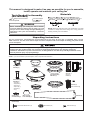
Unpacking Instructions
For your convenience, check-off boxes are provided next to each step. As each step is completed, place a check
mark in the box. This will insure that all steps have been completed and will be helpful in finding your place should
you be interrupted.
NOTE: If you are uncertain of part description, refer to exploded view illustration.
1. Check to see that you have received the following parts:
Do not install or use fan if any part is damaged or missing. This product is designed to use only those parts
supplied with this product and/or any accessories designated specifically for use with this product by
Fanimation. Substitution of parts or accessories not designated for use with this productby Fanimation could
result in personal injury or property damage.

5
Energy Efficient Use of Ceiling Fans
Using the Ceiling Fan Year Round
Summer Season: Use the ceiling fan in the counter-
clockwise direction. The airflow produced by the ceiling
fan creates a wind-chill effect, making you “feel” cooler.
Select a fan speed that provides a comfortable breeze,
lower speeds consume less energy.
Winter Season: Reverse the motor and operate the ceiling
fan at low speed in the clockwise direction. This produces
a gentle updraft, which forces warm air near the ceiling
down into the occupied space.Remember to adjust your
thermostat when using your ceiling fan - additional energy
and dollar savings could be realized with this simple step!
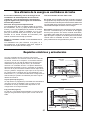
Electrical and Structural Requirements
Your new ceiling fan will require a grounded electrical
supply line of 120 volts AC, 60 HZ, 15 Amp Circuit.
Electrical code requires use of a fan-rated outlet box to
support the extra weight and motion associated with a
ceiling fan. A fan-rated box will be labeled as such and
typically supports up to a 70lbs ceiling fan. Fan-Rated
Outlet Boxes vary in ratings and design. Ensure the
ratings of your ceiling fan outlet box meet the
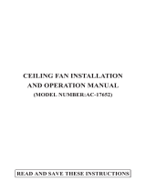
requirements for the ceiling fan being installed. Figure 1,
Figure 2 and Figure 3 depicts different structural
configurations that may be used for mounting the
outlet box.
Low-profile use (Figure 1)
A 1
2-in.-deep pancake box is meant to be screwed to a
joist or block. It’s used if only one cable is coming into
the box. It is also available in a saddle-mount
configuration.
CEILING
2" x 4"
CEILING JOIST
OUTLET BOX
Figure 1
Figure 2
2" x 4"
CEILING JOIST
CEILING
OUTLET BOX
Deep-profile use (Figure 2)
A 2-1
-in.-deep box can be attached to blocking
between joists and is roomy enough to handle more
than one cable.
Choosing the Appropriate Mounting Location
Ceiling fans should be installed, or mounted, in the middle
of the room and at least 7 feet from floor to the blade and
18 inches from wall to the blade. If ceiling height allows,
install the fan 8 - 9 feet from floor to the blade for optimal
airflow. Consult your Fanimation Retailer for optional
mounting accessories.
Turn Off When Not in the Room
Ceiling fans cool people, not rooms. If the room is
unoccupied, turn off the ceiling fan to save energy.
Ceiling fan performance and energy savings rely
heavily on the proper installation and use of the
ceiling fan. Here are a few tips to ensure efficient
product performance.

6
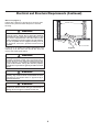
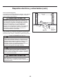
Electrical and Structural Requirements (Continued)
If your fan is to replace an existing light fixture, turn
electricity off at the main fuse box at this time and
remove the existing light fixture.
Turning off wall switch is not sufficient. To avoid
possible electrical shock, be sure electricity is
turned off at the main fuse box before wiring. All
wiring must be in accordance with National and
Local codes and the ceiling fan must be properly
grounded as a precaution against possible electrical
shock.
WARNING
To reduce the risk of fire, electrical shock, or
personal injury, mount fan to outlet box marked
acceptable for fan support of 15.88 kg (35 lbs) or less.
Use screws supplied with outlet box. Most outlet
boxes commonly used for support of light fixtures
are not acceptable for fan support and may need to
be replaced. Consult a qualified electrician if
in doubt.
WARNING
Brace use (Figure 3)
Paired with a deep box, this hanger is meant to span
between two joists and takes the place of wooden
blocking.
To avoid fire or shock, follow all wiring instructions
carefully. Any electrical work not described in these
instructions should be done or approved by a
licensed electrician.
WARNING
Figure 3
CEILING JOIST
CEILING
OUTLET BOX
Do not operate this fan with a variable (Rheostat) wall
controller or dimmer switch. Doing so could result in
damage to the ceiling fan's remote control unit.
WARNING

Figure 2
#8-32 Washer Head
Screw with Fiber Washer
(3 per assembly)
Motor Assembly
Blade
Motor
Assembly
Upper Housing
Cover
Figure 3
7
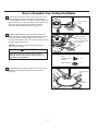
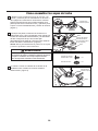
How to Assemble Your Ceiling Fan Blades
3. Reassemble the upper housing cover to the motor
assembly using the previously removed screws.
(Figure 3)
To reduce the risk of personal injury, do not bend the
NOTE: Periodically check blade hardware and
resecure if necessary.
2. Slide blades through slots in motor housing and
attach to the motor hub using the #8-32 washer head
screws and fiber washers. Make sure the screws
securing the blades to the motor hub are tight and are
properly seated.
(
Figure 2)
blade when installing, balancing the blades or
cleaning the fan. Do not insert foreign objects in
between the rotating blades.
WARNING
!
Figure 1
HARDWARE USED:
x 15
x 15
FIBER WASHER
#8-32
WASHER HEAD
SCREWS
Upper Housing
Cover
1. Remove the two set screws and locking nuts in the
downrod support of the motor assembly and retain
for reinstallation in Step 4 of Page 8. Disassemble the
upper housing cover by removing the six screws at the
top of the motor assembly and retain for Step 3.
Carefully twist and lift off the cover. (Figure 1)

Downrod
Set Screws (2)
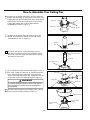
4. Thread downrod into the downrod support on top of
the motor. Install the clevis pin by aligning the holes
in the downrod support with holes in the downrod.
Secure clevis pin with hairpin clip. Tighten the two set
screws with nuts in the downrod support. (Figure 4)
WARNING
It is critical that the clevis pin in the downrod support
is properly installed and the set screws and nuts are
securely tightened. Failure to do so could result in
the fan falling.
5. Route wires through motor coupling cover, canopy
screw cover and ceiling canopy. (Figure 5)
Figure 3
Figure 5
Motor Coupling
Cover
Ceiling Canopy
Canopy Screw
Cover
Downrod
Set Screws and
Locking Nuts (2)
Clevis Pin
Hairpin Clip
Figure 4
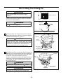
How to Assemble Your Ceiling Fan
8
2. Remove the hairpin clip and clevis pin from the
bottom of the downrod. Retain the pin and clip for
reinstallation in Step 4. (Figure 2)
Figure 2
Figure 1
Hairpin
Clip
Clevis Pin
wires
3. Loosen the two set screws and locking nuts in
the downrod support of the motor assembly. Route
the brown, blue, red, gray and yellow wires through
the downrod. (Figure 3)
Brown, Blue, Red,
Gray and Yellow wires
Pin
Downrod
Hanger Ball
Set Screw
1. Remove the hanger ball portion from the downrod/
hanger ball assembly by loosening the set screw in the
hanger ball until the ball falls freely down the downrod.
Remove the pin from the downrod, then remove the
hanger ball. Retain the pin and hanger ball for
reinstallation in Step 6. (Figure 1)

9
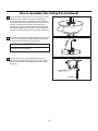
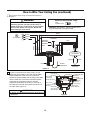
How to Assemble Your Ceiling Fan (continued)
7. Cut off excess lead wire approximately 6 to 9 inches
above top of the downrod. Strip insulation off 1/2 inch
from the end of each lead wire. (Figure 7)
Figure 6
Figure 7
8. Remove one of the two shoulder screws in the
hanger bracket and retain the screw for later. Loosen
the second shoulder screw without fully removing it.
(Figure 8)
Figure 8
6. Reinstall the hanger ball on the downrod as follows.
Route the
brown, blue, red, gray and yellow wires
through the hanger ball. Position the pin through the
two holes in the downrod and align the hanger ball so
the pin is captured in the groove in the top of the
hanger ball. Pull the hanger ball up tight against the
pin. Securely tighten the set screw in the hanger ball.
A loose set screw could create fan wobble. (Figure 6)
CAUTION
All set screws must be checked, and retightened where
necessary before installation.

WARNING
Failure to seat tab in groove could cause damage to
electrical wires and possible shock or
re hazard.
WARNING
To avoid possible shock, do not pinch wires between
the hanger ball assembly and the hanger bracket.
1. Securely attach the hanger bracket to the outlet box
(not included) using the outlet box screws and washers
supplied with the outlet box. (Figure 3)
WARNING
The outlet box must be securely anchored. Hanger
bracket must seat
rmly against outlet box. If the
outlet box is recessed, remove wall board until bracket
contacts box. If bracket and /or outlet box are not
securely attached, the fan could wobble or fall.
Outlet Box
Hanger
Bracket
Downrod/Hanger
Ball Assembly
Outlet Box
Hanger
Bracket
Screw (2)
Supplied with
Outlet Box
Tab
Flat Washer
10
How to Hang Your Ceiling Fan
NOTE: If you are not sure if the outlet box is grounded,
contact a licensed electrician for advice, as it must be
grounded for safe operation.
WARNING
The fan must be hung with at least 7’ of clearance
from
oor to blades. (Figure 2)
WARNING
To avoid possible re or shock, be sure electricity is
turned off at the main fuse box before hanging.
(Figure 1)
CEILING
FLOOR
NO LESS
THAN
7 FEET
Figure 3
Figure 4
Figure 2
Figure 1
MAIN FUSE BOX
2. Carefully lift the fan and seat the downrod/hanger ball
assembly on the hanger bracket that was just attached
to the outlet box. Be sure the groove in the ball is lined
up with tab on the hanger bracket. (Figure 4)
This fan is intended for standard and angled mounting
options only. Closemount and flushmount options are
not available. For angled ceilings, note the angle can
be no more than 19°.

11
How to Wire Your Ceiling Fan
Hanger Bracket
Receiver
Dip Switch
NOTE: Supply wires
omitted for clarity
NOTE: If fan or supply wires are different colors than indicated, have this unit installed by a qualified electrician.
1. To set the code on receiver unit, slide dip switches to
the same positions as set on the remote control.
(Figure 1)
NOTE: The remote unit has 32 different code
other remote units, simply change the combination code
NOTE: Factory setting is all up. Do not use this position.
2. Slide the receiver into the hanger bracket before
wiring as shown in figure 3.
MAIN FUSE BOX
Figure 1
Figure 3
Figure 2
NOTE:
If you are not sure if the outlet box is
grounded, contact a licensed electrician for advice, as
it must be grounded for safe operation.
WARNING
To avoid possible electrical shock, be sure electricity is
turned off at the main fuse box before wiring. (Figure 2)
Dip Switch
ON
1 2 3 4 5
Receiver
Remote Control
Dip Switch

12
Figure 4
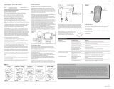
3. Connect wires using connectors as shown in
Figure 4.
x 9
WIRE
CONNECTORS
RECEIVER HARDWARE USED:
CAUTION: INCORRECT WIRE CONNECTION
COULD DAMAGE THIS RECEIVER.
How to Wire Your Ceiling Fan (continued)
WARNING
Check to see that all connections are tight,
including ground, and that no bare wire is
visible at the wire connectors. Do not operate
fan until the blades are in place. Noise and
motor damage could result.
BLUE
BROWN
BLACK
WHITE
L
N
AC POWER
BLUE
LIGHT KIT
YELLOW
/ GREEN (2)
GROUND
HANGER
BRACKET
HANGER
BALL
DC MOTOR
BLACK
ANTENNA
Receiver
BLACK
WHITE
BLUE
BROWN
RED
GRAY
YELLOW
RED
GRAY
YELLOW
WHITE
RED
L1
WARNING
The blades must be installed first before programming
is performed.
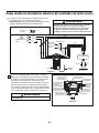
Listed Outlet Box
White Wire
from Supply
Green Wire
from Supply
(Ground)
Household
Supply
Black Wire
from Supply
Black Wire
from Receiver
White Wire
from Receiver
Green Wire
from Hanger
Bracket (Ground)
Green Wire
from Hanger
Ball (Ground)
Green Wire
from Receiver (2)
(Ground)
Receiver
Figure 5
Red Wire
from Supply
4. After connections have been made, put the
white and green leads to one side and the black
leads towards the other side, the connection
should be turned upward and carefully push leads
into the outlet box. The wires should be spread
apart with the grounded conductor and the
equipment-grounding conductor on one side of
the outlet box and the ungrounded conductor on
the other side. (Figure 5)

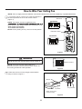
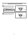
How to Install Your Canopy Housing
2. Securely attach and tighten the canopy screw
cover over the shoulder screws in the hanger bracket
utilizing the keyslot twist-lock feature. (Figure 2)
WARNING
To avoid possible fire or shock, make sure that the
electrical wires are completely inside the canopy
housing and not pinched between the housing and the
ceiling.
NOTE: This step is applicable after the neccessary wiring is completed.
Canopy Screw
Cover
Ceiling Canopy
13
1. Assemble canopy by rotating key slot in canopy
over shoulder screw in hanger bracket, taking care
not to pinch the wires. Tighten shoulder screw. Fully
assemble and tighten second shoulder screw that
was previously removed. (Figure 1)
Figure 1
Figure 2

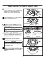
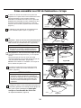
4. Assemble the LED assembly to the light kit
assembly use the removed screws in Step 2.
(Figure 4)
The light source is designed for this specific
application and can overheat if serviced by untrained
personnel. If any servicing is required, the product
should be returned to an authorized service facility
for examination or repair.
CAUTION
Light Kit Assembly
Figure 5
Glass
LED
Assembly
Figure 4
14
How to Assemble Your Light Kit Assembly or Cap
1. Remove one of the three screws in the adaptor
plate at the bottom of the motor assembly. Slightly
loosen the remaining two screws. Assemble the light
kit assembly to the adaptor plate of the motor
assembly using the two key slots in the light kit
assembly. Replace the third screw and secure all
three screws. (Figure 1)
2. Remove the three screws in the light kit assembly.
Retain the screws for Step 4. (Figure 2)
Motor
Assembly
Figure 1
Figure 2
Light Kit
Assembly
Light Kit
Assembly
Connect the 2 single pin connectors from the LED
assembly to the 2 single pin connectors from motor
assembly. (Figure 3A)
To reduce the risk of electric shock, disconnect the
electrical supply circult to the fanbeforeinstalling
light kit.
CAUTION
3B. (Option B--for use with steel cap)
If you want to install the steel cap and not the light kit.
Assemble the steel cap to the light
kit
assembly by
twisting in a clockwise direction. (Figure 3B)
NOTE:
If you have installed your fan with the steel
cap, skip Steps 4 and 5.
3A. (Option A--for use with light kit)
Figure 3A
Figure 3B
LED Assembly
Motor
Steel Cap
Light Kit Assembly
5. Secure the glass to light kit by twisting in a
clockwise direction. Twist the glass gradually until it
snaps onto the light kit. Do not over-tighten.
(Figure 5)
Light Kit
Assembly

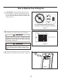
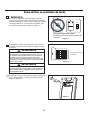
How to Operate Your Ceiling Fan
MAIN FUSE BOX
Figure 2
Figure 1
For illustrative purposes only-not
intended to cover all types of controls
1. IMPORTANT: Using a full range dimmer switch
(not included) to control fan speed will damage the
fan. To reduce the risk of fire or electrical shock, do
not use a full range dimmer switch to control the fan
speed. (Figure 1)
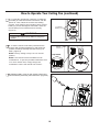
3. Remove the battery cover from remote control by
screwdriver and retain the screw for later. (Figure 3)
2. Restore electrical power to the outlet box by turning
the electricity on at the main fuse box. (Figure 2)
Check to see that all connections are tight, including
ground, and that no bare wire is visible at the wire
connectors, except for the ground wire. Do not
operate fan until the blades are in place. Noise and
fan damage could result.
WARNING
Do not operate this fan with a variable (Rheostat)
wall controller or dimmer switch. Doing so could
result in damage to the ceiling fan's remote control
unit.
WARNING
15
Figure 3

3V CR2032
Battery (2 pcs)
Figure 4
4. To make fan operational, install two 3V batteries
(included) in hand-held remote transmitter, with fan
power off. Then, follow the remote code setting
process. If not used for long periods of time, remove
battery to prevent damage to transmitter. Store the
remote away from excessive heat or humidly.
(Figure 4)
Chemical Burn Hazard. Keep batteries away from
children.
WARNING
NOTE: The remote unit has 32 different code
combinations. To prevent possible interference from
or to other remote units, simply change the
combination code in the remote and receiver.
NOTE: Factory setting is all up. Do not use this
position.
How to Operate Your Ceiling Fan (continued)
16
5.
To set the remote code same positions as the
receiver with a small screwdriver or ball point pen
(neither included), slide dip switches firmly up or
down. (Figure 5)
Figure 6
6. Replace battery cover on the remote control and
secure with the previously removed screw. (Figure 6)
Remote
Control
Dip Switch
Figure 5

How to Operate Your Ceiling Fan (continued)
17
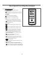
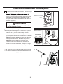
• Sleep Timer:
The fan and light will turn off after 1 hour.
The fan and light will turn off after 3 hours.
The fan and light will turn off after 6 hours.
7. Remote functions: (Figure 7)
• Indicator LED light: fan speed and light
dimmer indicator
• Fan Speed:
• button: Tap once to turn off the fan. Press and
hold this button for 5 seconds to turn on or turn off
the buzzer.
Turn on fan and turn speed up.
Turn on fan and turn speed down.
• Home Away: Tap this button, the light will
blink twice signaling this feature is on; the fan
will turn off and the light will randomly turn on
and off while you are away. Pressing any button
will cancel the feature.
• Fresh Air: Fan speed will modulate to
simulate a natural breeze.
• Safe Exit: Tap once, the light will blink once;
fan and light will turn off after 1 minute. Pressing
any button will cancel this feature.
Figure 7
• Reverse button:
Summer- The fan runs counterclockwise.
Airflow will provide a downward cooling breeze.
Winter- The fan runs clockwise. Airflow will force
warm air downward without a noticeable breeze.
In order to reverse the direction of the fan, the fan
must be running.
• Light button: Turn ON\OFF the light.
Press to turn on the light and hold to dim or
brighten light to desired level, then release.
Press this button to switch color temperature
when the light is on.

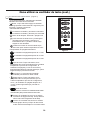
18
Figure 1
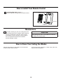
1. Installing Wall Plate: (Figure 1)
Attach wall plate using the two provided screws.
How to Install Your Remote Control
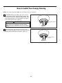
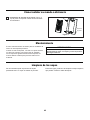
Maintenance
How to Clean Your Ceiling Fan Blades
Periodic light dusting of the blades is recommended.
A feather duster will work best.
Avoid using water, cleansers, or harsh rags, which can
warp and ruin the blades.
CAUTION
1. Periodic cleaning of your new ceiling fan is the
only maintenance that is needed. When cleaning,
use only a soft brush or lint free cloth to avoid
scratching the finish. Abrasive cleaning agents
are not required and should be avoided to
prevent damage to finish.
Do not use solvents when cleaning your ceiling fan. It
could damage the motor or the blades and create the
possibility of electrical shock.
Screws (2)
Wall Plate

19
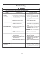
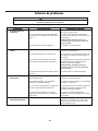
For your own safety, turn off power at fuse box or circuit breaker before trouble shooting your fan.
Some suggested remedies require the attention of a licensed electrician.
WARNING
!
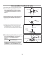
Trouble Probable Cause Suggested Remedy
1.FAN WILL
NOT START
1. Check main and branch circuit fuses
or circuit breakers.
2. Check line wire connections to fan
and switch wire connections in the
switch housings.
CAUTION: Make sure main power is
turned off !
1. Fuse or circuit breaker blown.
2. Loose power line connections to the
fan, or loose switch wire connections
in the switch housing.
2.FAN SOUNDS NOISY
1. Attach blades to fan before operating.
2. Check to make sure all screws in
motor housing are snug (do not over-
tighten).
3. Check to make sure the screws which
attach the fan blade to the motor
assembly are tight.
3. Check to make sure the screws which
attach the fan blade to the motor
assembly are tight.
CAUTION: Make sure main power is
turned off !
4. Tighten set screw securely.
1. Blades not attached to fan.
2. Loose screws in motor housing.
3. Screws securing fan blade to motor
assembly are loose.
3. Screws securing fan blade to motor
assembly are loose.
4. Lower housing support set screw
loose.
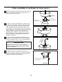
3.FAN WOBBLES
EXCESSIVELY
1. Tighten both setscrews securely in
downrod support.
2. Tighten the setscrew in the downrod/
hanger ball assembly.
4. Tighten the hanger bracket screws to
the timber batten, and secure outlet
box.
1. Setscrew in downrod support is loose.
2. Setscrew in downrod/hanger ball
assembly is loose.
4. Hanger bracket and/or ceiling timber
batten is not securely fastened.
4.
NOT ENOUGH AIR
MOVEMENT
Troubleshooting
3. Replace with fresh battery.
1. If possible, consider using a longer
downrod. (not included, you can buy
the longer downrod from fanimation.
com).
3. Dead battery in remote control.

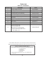
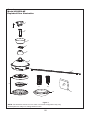
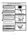
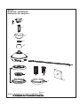
Parts List
Model No. LP8359LAZ
20
Reference # Description Part #
AP835902LAZMotor Coupling Cover Assembly
5
AMA8359-1LAZMotor Assembly
6
AP835905DWABlade Set
7
AP835907LAZ
8
Light Kit Assembly with Glass
AP835910GT3050LED Assembly
9
HDWLP8359LAZ
P835909LAZ
10
Steel Cap
13
1
APP799004BLHanger Bracket Assembly
ADRAC4GT1-45LAZ
2
Hanger Ball/Downrod Assembly
P835901LAZ
3
Ceiling Canopy
4 APPCP1101LAZCanopy Screw Cover Assembly
Wire Connectors (4)
Loose Hardware Bag:
Blade Mounting Hardware Bag:
Washer Head Screws #8-32 (16)
Fiber Washer (16)
11
Hand-held Remote TR305S
12
Receiver RCCD835901
Before discarding packaging material, be certain all parts have been removed.
** Insert FINISH CODES (Refer to fan model number located on downrod support)
HOW TO ORDER REPAIR PARTS
When ordering repair parts, always give the following information:
Contact [email protected] or call 1.888.567.2055
for repair parts.
• Fan Model Number
• Part Number
• Part Description
• Date Code
Page is loading ...
Page is loading ...
Page is loading ...
Page is loading ...
Page is loading ...
Page is loading ...
Page is loading ...
Page is loading ...
Page is loading ...
Page is loading ...
Page is loading ...
Page is loading ...
Page is loading ...
Page is loading ...
Page is loading ...
Page is loading ...
Page is loading ...
Page is loading ...
Page is loading ...
Page is loading ...
Page is loading ...
Page is loading ...
Page is loading ...
Page is loading ...
-
 1
1
-
 2
2
-
 3
3
-
 4
4
-
 5
5
-
 6
6
-
 7
7
-
 8
8
-
 9
9
-
 10
10
-
 11
11
-
 12
12
-
 13
13
-
 14
14
-
 15
15
-
 16
16
-
 17
17
-
 18
18
-
 19
19
-
 20
20
-
 21
21
-
 22
22
-
 23
23
-
 24
24
-
 25
25
-
 26
26
-
 27
27
-
 28
28
-
 29
29
-
 30
30
-
 31
31
-
 32
32
-
 33
33
-
 34
34
-
 35
35
-
 36
36
-
 37
37
-
 38
38
-
 39
39
-
 40
40
-
 41
41
-
 42
42
-
 43
43
-
 44
44


Fanimation LP8359L Owner's manual
- Category
- Household fans
- Type
- Owner's manual
Ask a question and I''ll find the answer in the document
Finding information in a document is now easier with AI
in other languages
Other documents
-
 Fanimation Studio Collection LP7668LBL Installation guide
-
Unbranded 24006-BK Installation guide
-
-
Blaupunkt BP2012 User manual
-
 Brightwatts 52-CRB User manual
-
 Honeywell Ceiling Fans 50614-01 User guide
-
 Designers Choice Collection AC17652-SN Installation guide
-
 Hunter Fan 27157 User manual
-
Parrot Uncle F6108110V Installation guide
-


