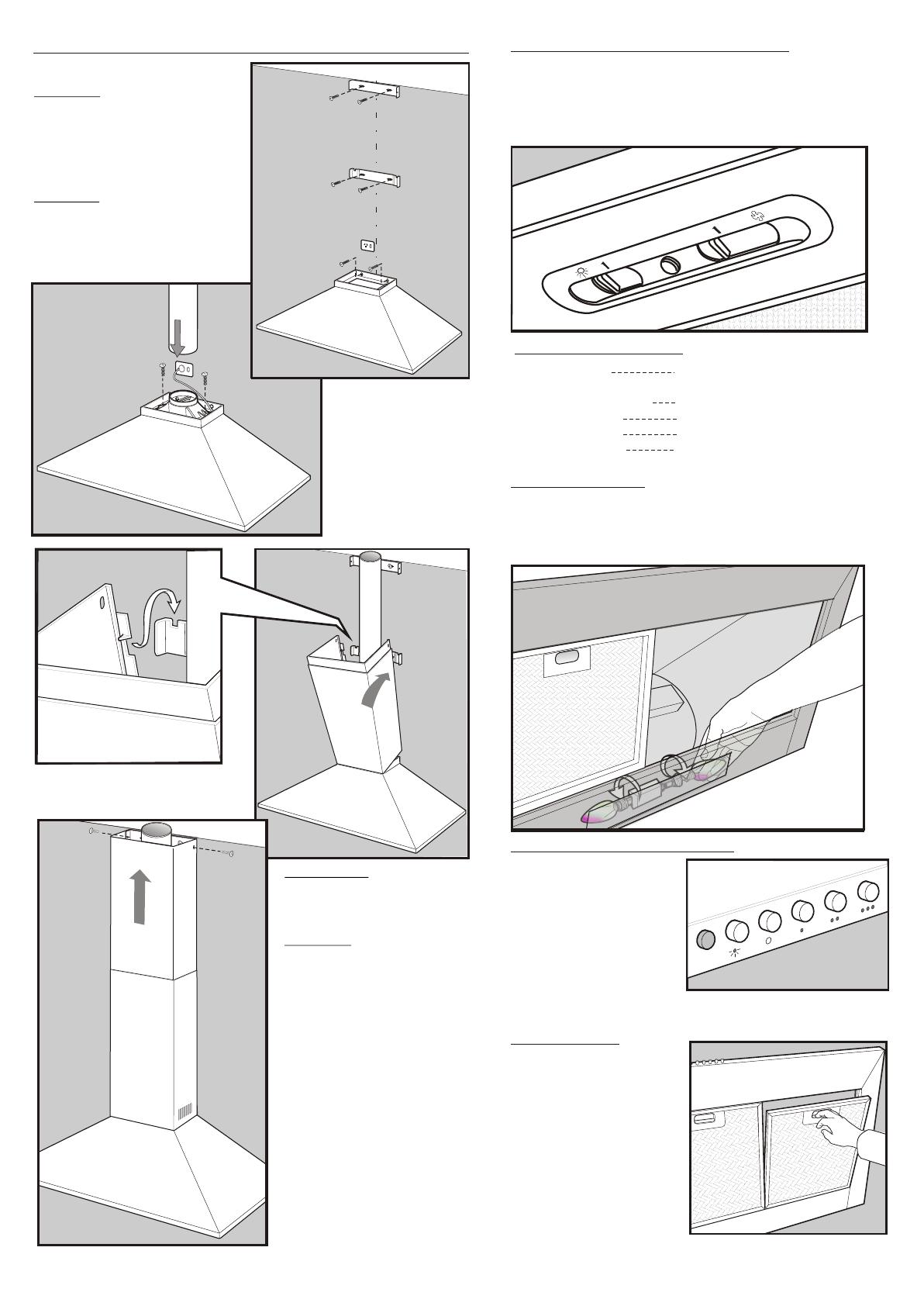
Light switch:
Extractor fan switch:
Slide position I:
Slide position 2:
Slide position 3:
This switch is used to turn the
light fitted in the hood on and off.
Used to select fan speeds.
Fan speed Low
Fan speed Medium
Fan speed High
Slide switch controls:
Clean grease filters every
three to four weeks
maximum.
Greasy filters are a fire
risk.
Remove the grease filters,
soak and agitate in hot
soapy water.
Rinse, drain and shake
well before replacing filters.
Do not use oven cleaners
or other caustic materials.
Maintenance:
Light switch: Depress
light button to turn light
ON. Press light button to
turn light OFF.
Extractor fan switch
interlocked switching:
Select a fan speed,
depress button to turn fan
On. Press button (O) to
turn fan OFF.
Press button switch controls
Ensure the appliance is switched off before carrying out
maintenance, to avoid any possibility of electric shock.
Remove grease filter to replace lamp. Replace with 40W
(maximum) E14 candle lamp.
Replacing lamps:
COOKER HOOD OPERATION
F
G
G
RECOMMENDED INSTALLATION SEQUENCE
ceiling
E
Diagram E
Install cooker hood body.
Determine working height, mark
wall to suit.
Install cover flue mounting
brackets.
Diagram F
Fix duct transition to cooker hood
body.
Install internal exhaust duct to suit
installation type.
Diagram(s) G
Install bottom section of
telescopic flu e c ove r.
H
Best results are obtained by using a low fan speed for
normal conditions and a high fan speed when odours are
more concentrated. Turn the hood on a few minutes before
you start cooking. It should by left on after cooking for about
15 minutes or until all odours have disappeared.
33
22
00
00
Diagram H
Install top section of
telescopic flue cover.


