Raymarine Digital Radome Owner's manual

Category
Car navigation systems
Type
Owner's manual

This manual is also suitable for

Raymarine Digital Radome is a high-performance radar system designed for leisure marine boats and workboats, providing exceptional target detection and discrimination capabilities. Its compact radomes house a 4kW solid-state transmitter, ensuring reliable operation and excellent range. With advanced features like MARPA, dual range operation, and easy integration with Raymarine multi-function displays, the Digital Radome offers a user-friendly and feature-rich radar experience.

Raymarine Digital Radome is a high-performance radar system designed for leisure marine boats and workboats, providing exceptional target detection and discrimination capabilities. Its compact radomes house a 4kW solid-state transmitter, ensuring reliable operation and excellent range. With advanced features like MARPA, dual range operation, and easy integration with Raymarine multi-function displays, the Digital Radome offers a user-friendly and feature-rich radar experience.

Installation instructions
ENGLISH
Date: 02-2009
Document number: 81313-4
© 2009 Raymarine UK Limited
Digital Radome
81313_3.book Page 1 Tuesday, February 24, 2009 5:04 PM
Trademarks and registered trademarks
Autohelm, HSB, RayTech Navigator, Sail Pilot, SeaTalk and Sportpilot are
UK registered trademarks of Raymarine UK Limited. Pathfinder and Rayma-
rine are UK registered trademarks of Raymarine Holdings Limited.
45STV, 60STV, AST, Autoadapt, Auto GST, AutoSeastate, AutoTrim, Bidata,
GSeries, HDFI, LifeTag, Marine Intelligence, Maxiview, On Board, Raychart,
Raynav, Raypilot, RayTalk, Raystar, ST40, ST60+, Seaclutter, Smart Route,
Tridata and Waypoint Navigation are trademarks of Raymarine UK Limited.
All other product names mentioned are trademarks or registered trade-
marks (if applicable) of their respective companies.
© Raymarine UK Ltd 2009
81313_3.book Page 2 Tuesday, February 24, 2009 5:04 PM
Contents i
Contents
Important information ................................................................1
Introduction........................................................................................... 1
Intended use ......................................................................................... 1
Safety notices........................................................................................ 1
FCC Notice ............................................................................................ 2
WARNING ............................................................................................. 2
Waste Electrical and Electronic Equipment Directive............................. 2
EMC conformance................................................................................. 2
Declaration of conformity...................................................................... 2
Multi-function display software version ................................................ 3
Warranty ............................................................................................... 3
Handbook information .......................................................................... 3
Installation ....................................................................................5
EMC installation guidelines................................................................... 5
Box contents ......................................................................................... 6
Required tools ....................................................................................... 6
Digital Radome scanner dimensions...................................................... 7
18” Digital Radome scanner.............................................................. 7
24” Digital Radome scanner.............................................................. 7
Planning the installation ....................................................................... 8
Cable requirements ............................................................................... 9
Scanner cables................................................................................... 9
Running the cable to the scanner ...................................................... 9
Power requirements......................................................................... 10
Grounding the radar system ............................................................ 10
Connecting the power and digital cables......................................... 11
Mounting the scanner ..................................................................... 14
Setting up the scanner..................................................................... 15
Maintenance and troubleshooting ..........................................17
Introduction ..................................................................................... 17
Maintenance.................................................................................... 17
Troubleshooting............................................................................... 17
Technical support............................................................................. 19
Technical specification.............................................................. 21
RD418D 18”Digital Radome scanner unit ..........................................21
RD424D 24”Digital Radome scanner unit ..........................................23
81313_3.book Page i Tuesday, February 24, 2009 5:04 PM
ii Digital Radome Scanner - User Guide
81313_3.book Page ii Tuesday, February 24, 2009 5:04 PM
Important information 1
Important information
Introduction
This handbook contains an explanation of how to install, connect and
maintain your Digital Radome scanner and covers the following models:
RD418D - 18” 4 kW Digital Radome scanner.
RD424D - 24” 4 kW Digital Radome scanner.
Your radar has been designed and manufactured to meet the rigorous
demands of the marine environment. However, no machine can perform its
intended function unless installed, operated and maintained properly.
Please carefully read and follow the recommended procedures for installa-
tion contained in this handbook.
When properly installed and operated, the use of this radar conforms to:
IEEE C95.1 - 2005 - Standard for Safety Levels with respect to Human
Exposure to Radio Frequency Electromagnetic Fields, 3 kHz to 300GHz.
ICNIRP Guidelines 1998 - International Commission on Non-Ionising
Radiation Protection: Guidelines for limiting exposure to time-varying
electric, magnetic and electro-magnetic fields (up to 300GHz) 1998.
Intended use
This product is a radar scanner intended for use within a navigational radar
system. The intended application is for leisure marine boats and work
boats not covered by IMO/SOLAS carriage requirements.
Installation and operation of this radar may be subject to individual
licensing of the equipment, operator or vessel. You are strongly advised to
check with the requirements of the licensing authority of your national
administration. In case of difficulty, contact your local Raymarine dealer.
Safety notices
WARNING
Radio Frequency Radiation Hazard
The radar antenna emits electromagnetic energy at micro-
wave radio frequencies which can be harmful, particularly to
your eyes. DO NOT look at the antenna at close range.
It is important that the radar is turned off whenever personnel
are required to come close to the scanner assembly. It is
recommended that the radar scanner is mounted out of range
of personnel (above head height).
The maximum power density level which is considered safe for
general public exposure is 10 W/m
2
, and for occupational expo-
sure it is 100 W/m
2
. The distances from the radar scanner
within which these levels may be exceeded are given below:
Model
Distance to 100 W/m
2
point
Distance to 10 W/m
2
point
RD418D
Max power density at any
distance is <100 W/m
2
1.0m (worst case)
RD424D
Max power density at any
distance is <100 W/m
2
1.0m (worst case)
81313_3.book Page 1 Tuesday, February 24, 2009 5:04 PM
2 Digital Radome Scanner - User Guide
FCC Notice
Changes or modifications to this equipment, not expressly
approved in writing by Raymarine Inc., could violate compli-
ance with FCC rules and void the operator’s authority to
operate the equipment.
Waste Electrical and Electronic Equipment
Directive
The Waste Electrical and Electronic Equipment (WEEE) Direc-
tive requires the recycling of waste electrical and electronic
equipment. Whilst the WEEE Directive does not apply to some
of Raymarine’s products, we support its policy and ask you to
be aware of how to dispose of this product.
The crossed out wheelie bin symbol, illustrated above, and found on our
products signifies that this product should not be disposed of in general
waste or landfill.
Please contact your local dealer, national distributor or Raymarine Tech-
nical Services for information on product disposal.
EMC conformance
All Raymarine equipment and accessories are designed to the best industry
standards for use in the recreational marine environment. The design and
manufacture of Raymarine equipment and accessories conform to the
appropriate Electromagnetic Compatibility (EMC) standards, but correct
installation is required to ensure that performance is not compromised.
Declaration of conformity
Raymarine UK Limited hereby declare that the products to which this
manual relates comply with the appropriate requirements and provisions of
the R&TTE Directive 1999/5/EC.
The full Declaration of Conformity may be viewed on the relevant product
pages at www.raymarine.com
WARNING
High Voltage
The scanner unit contains high voltages. Adjustments
require specialized service procedures and tools only avail-
able to qualified service technicians - there are no user
serviceable parts or adjustments. The operator should
never remove the scanner unit internal covers or attempt
to service the equipment.
WARNING
Product installation
This equipment must be installed in accordance with the
instructions contained in this handbook. Failure to do so
could result in poor product performance, personal injury
and/or damage to your boat.
81313_3.book Page 2 Tuesday, February 24, 2009 5:04 PM
Important information 3
Multi-function display software version
The Digital Radome scanner can be connected directly to a C-Series or
E-Series display, or to a C-Series, E-Series or G-Series display via a
SeaTalk
hs
switch.
The Digital Radome scanner is compatible with the following multi-func-
tion displays:
C90W, C120W, and C140W C-Series displays.
E80, E120 E-Series displays.
G120, G150, G170, and G190 G-Series displays.
For operation of your scanner, the multi-function display unit requires the
latest software version.
After installing your scanner, download the latest software for your multi-
function display from the Raymarine website (www.raymarine.com).
To find out whether your display is using the latest software version, switch
on the display and check the version number on the navigation warning
screen. However, if a scanner is not connected to the multi-function
display, the version number will only be displayed for 10 seconds.
For information on how to update your multi-function display software,
please refer to the instructions on the Raymarine website, or contact
Raymarine technical support.
Warranty
To register your new Raymarine product, please take a few minutes to fill
out the warranty card. It is important that you complete the owner infor-
mation and return the card to receive full warranty benefits. Alternatively
you can register your product on line at www.raymarine.com
Handbook information
The technical and graphical information contained in this handbook, to the
best of our knowledge, was correct as it went to press. However, our policy
of continuous improvement and updating may change product specifica-
tions without prior notice. As a result, unavoidable differences between the
product and handbook may occur from time to time.
81313_3.book Page 3 Tuesday, February 24, 2009 5:04 PM
4 Digital Radome Scanner - User Guide
81313_3.book Page 4 Tuesday, February 24, 2009 5:04 PM
Installation 5
Installation
EMC installation guidelines
All Raymarine equipment and accessories are designed to the best industry
standards for use in the recreational marine environment.
Their design and manufacture conforms to the appropriate Electromagnetic
Compatibility (EMC) standards, but correct installation is required to
ensure that performance is not compromised. Although every effort has
been taken to ensure that they will perform under all conditions, it is
important to understand what facts could affect the operation of the
product.
The guidelines here describe the conditions for optimum EMC performance,
but it is recognized that it may not be possible to meet all of these condi-
tions in all situations. To ensure the best possible conditions for EMC
performance within the constraints imposed by any location, always ensure
the maximum separation possible between different items of electrical
equipment.
For optimum EMC performance, it is recommended wherever possible:
Raymarine equipment and cables connected to it are:
At least 3 ft. (1m) from any other equipment transmitting or
carrying radio signals. In the case of Single Side Band (SSB) radio,
the distance should be increased to 7 ft. (2m).
More than 7 ft. (2m) from the path of a radar beam. A radar beam
can normally be assumed to spread 20 degrees above and below
the radiating element.
The equipment is supplied from a separate battery to that used for
engine start. Voltage drops below 10.8 V, and starter motor transients,
can cause the equipment to reset. This will not damage the equipment,
but may cause the loss of some information and may change the oper-
ating mode.
Only Raymarine-specified cables must be used. Cutting and rejoining
these cables can compromise EMC performance.
81313_3.book Page 5 Tuesday, February 24, 2009 5:04 PM
6 Digital Radome Scanner - User Guide
Box contents
Components are dependant on your system package, but are either:
18” 4 kW Digital Radome scanner, or
24” 4 kW Digital Radome scanner.
Fixing bolts and washers.
Denso Paste.
Handbook.
Required tools
Radome Scanner
Installation template
D11364-2
Drill 4 holes, 10 mm diameter
(18'' and 24'' Radomes)
141.5 mm
27.5 mm
18'' or 24'' Radome Mounting Template
Center Line of Radome
3026-136-C
Artwork Number 3032-866-B
Center Line of Radome
Forward
233 mm
Denso Paste
M8 bolt (x4)
Spring
washer (x4)
Flat
washer (x4)
Drill
Adhesive tape
10 mm drill bit
Torque wrench
13 mm socket
D11365-1
81313_3.book Page 6 Tuesday, February 24, 2009 5:04 PM
Installation 7
Digital Radome scanner dimensions
18” Digital Radome scanner
24” Digital Radome scanner
346 mm (13.62 in)
diameter
521 mm (20.5 in)
diameter
233 mm
(9.17 in)
D11356-1
247 mm (9.7 in)
116.5 mm
(4.58 in)
141.5 mm
(5.57 in)
27.5 mm
(0.92 in)
D11357-1
247 mm (9.7 in)
233 mm
(9.17 in)
116.5 mm
(4.58 in)
141.5 mm
(5.57 in)
27.5 mm
(1.08 in)
346 mm (13.62 in)
diameter
652 mm (25.67 in)
diameter
81313_3.book Page 7 Tuesday, February 24, 2009 5:04 PM
8 Digital Radome Scanner - User Guide
Planning the installation
Mount the scanner as high as possible above the waterline for better long
range performance, but make sure it:
is above head height.
is easily accessible.
is as near to the boat’s centerline as possible.
is on a rigid and stable platform.
is clear of large objects such as the flybridge, large engine stacks,
searchlights, horns or masts.
is clear of heat and fumes.
is at least 1 m away from a magnetic compass or other equipment
antenna.
Don’t put the scanner so high, that it is affected by the pitching and rolling
of the boat.
Mount the scanner so that the array rotates parallel to the waterline.
The radar beam is approximately 25
o
wide in the vertical direction, giving
good target detection when your boat pitches and rolls.
Planing hull and some displacement hull boats adopt a higher bow angle
when the boat is at cruising speed, giving poor target detection. It may be
necessary to lower the radar beam back towards the parallel, by shimming
the rear of the radar, so that the beam points slightly down when the boat
is at rest. Refer to the diagram on page 14 for more information.
D11358-1
12.5°
12.5°
D11359-1
Wedge or
washers
Forward
D11360-1
81313_3.book Page 8 Tuesday, February 24, 2009 5:04 PM
Installation 9
Cable requirements
You must consider the following points before installing the system cables:
You need to connect the scanner to the multi-function display unit and
power (and, if appropriate, via a SeaTalk
hs
switch).
All cables should be adequately clamped and protected from physical
damage and exposure to heat - avoid running cables through bilges or
doorways, or close to moving or hot objects.
Acute bends must be avoided. The digital cable for connecting the
Digital Radome scanner to a multi-function display and power source
has a minimum bend radius of 45mm (or diameter of 90mm).
Where a cable passes through an exposed bulkhead or deckhead, a
watertight gland or swan neck tube should be used.
Avoid cutting and rejoining cables.
Scanner cables
Running the cable to the scanner
DO NOT pull the cable through bulkheads using a cord
attached to the connector. This could damage connections.
The cable connector is at the rear of the scanner unit. If the unit is mounted
on a hollow mast, the cable may be run inside the mast and connected to
the unit. Make sure that the cable does not chafe where it enters and exits
the mast. To minimize electrical interference try to avoid running radar
cables near other onboard electrical equipment. It is also good practice to
avoid running radar cables in parallel with other antenna or power cables.
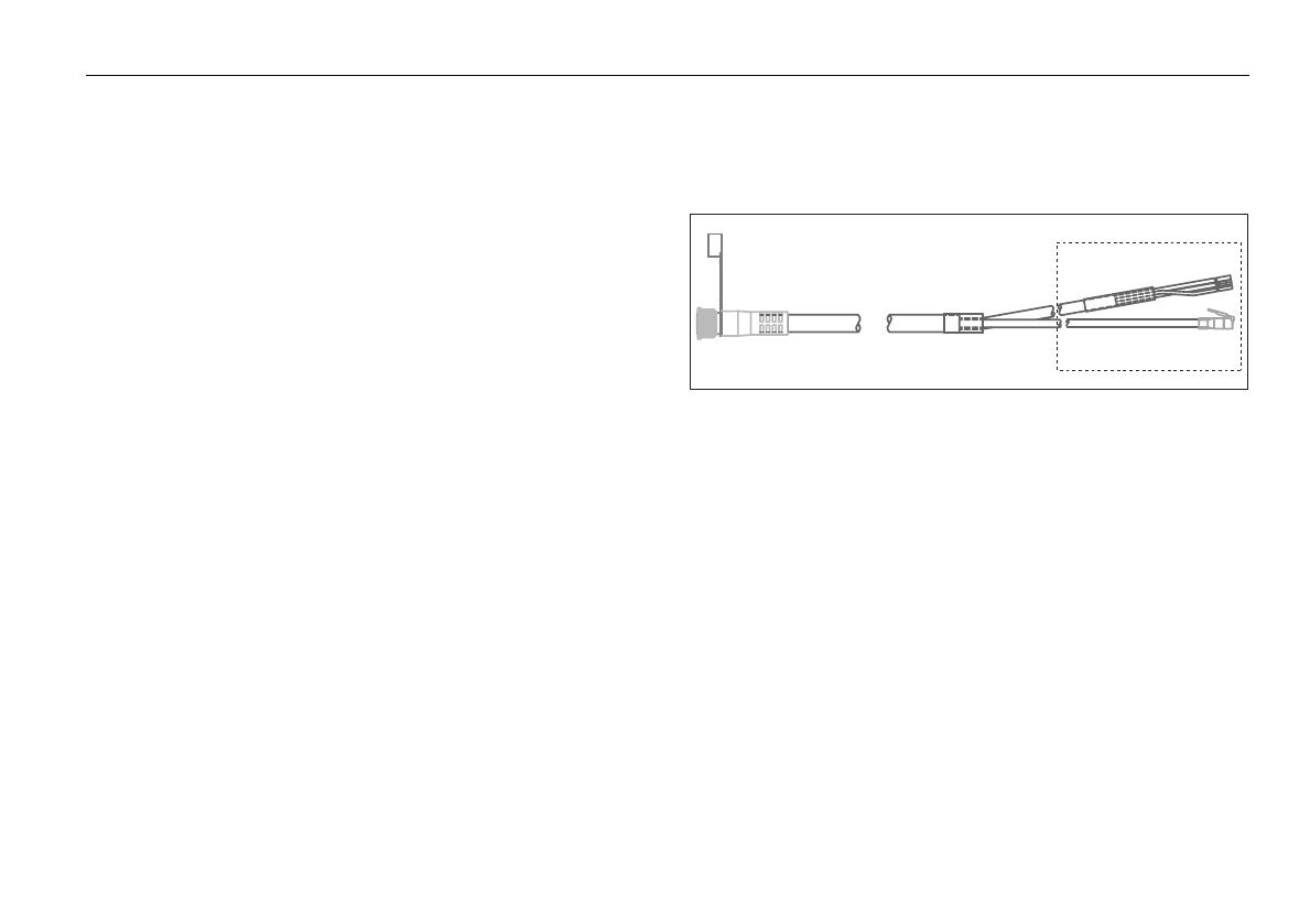
Digital cable
A digital cable, illustrated below, is required. This provides both power and
SeaTalk
hs
signals to the Digital Radome scanner. It is fitted with a
SeaTalk
hs
plug, and power cores for connecting to the scanner.
Digital cables are available in the following lengths:
Part No. A55076 - 5 m cable.
Part No. A55077 - 10 m cable.
Part No. A55078 - 15 m cable.
Part No. A55079 - 25 m cable.
The following extension cables are also available:
Part No. A92141 - 2.5 m extension cable.
Part No. A55080 - 5 m extension cable.
Part No. A55081 - 10 m extension cable.
For boats with 12 V DC power systems, the maximum cable length is 25 m
(including any extension). If you need to run a longer cable length with a
12v supply, please contact Raymarine technical support for further advice.
Note:
Do not make your own cables for use with the Digital Radome
scanner. Only use official Raymarine cables.
To Digital Radome scanner
To display and power
D11371_1
81313_3.book Page 9 Tuesday, February 24, 2009 5:04 PM
10 Digital Radome Scanner - User Guide
Power cables
Digital Radome radar systems are intended for use on boat’s DC power
systems operating in the range 12 to 24 V DC. The Digital Radome scanners
should not be used on nominal 32 V systems.
If you are replacing an existing (Analog) Radome scanner with a Digital
Radome scanner, you must replace the existing cable with a digital cable,
as described on page 9.
Power requirements
This radar is NOT recommended for use on ‘positive’ ground
boats. The power cable earth screen must be connected to
the boat’s ground.
The boat’s power system should be either:
Negative grounded, with the negative battery terminal connected to
the boat’s ground, or,
Floating with neither battery terminal connected to the boat’s ground.
The following diagram shows the cable’s power and ground connections:
Fuse requirements
The power connection to the Digital Radome scanner should be made at
either the output of the battery isolator switch, or at a DC power distribu-
tion panel. The power connection must be protected by a thermal circuit
breaker or fuse, fitted close to the power source. The following table
details the fuse requirements for both 18” and 24” Digital Radomes:
WARNING: If there is not a thermal circuit breaker or fuse in
your power circuit (for example, fitted to your DC distribu-
tion panel), you must fit an inline breaker or fuse to the
positive (red) connection of the power cable.
Grounding the radar system
It is important that an effective radio frequency (RF) ground is connected to
the radar system.
You must ground the radar by connecting the drain wire (screen) of the
power cable to the nearest ground point of your boat’s RF ground system.
Full details can be found in the Owner’s Handbook for your multi-function
display unit.
If you need to extend the wire, the extension wire should be an 8 mm braid
or 6 mm
2
(AWG 10) multi-strand cable.
If your vessel does not have an RF system, connect the drain wire to the
negative battery terminal.
Note:
Use only this ground connection.
Red - Battery +ve (12/24 V)
Black - Battery -ve (0 V)
Ground
D8865_1
Table 2-1: Fuse requirements
Power supply Device Rating
12 V Isolator Switch 20 A
Thermal Breaker 10 A
Fuse 15 A
24 V Isolator Switch 15 A
Thermal Breaker 5 A
Fuse 8 A
81313_3.book Page 10 Tuesday, February 24, 2009 5:04 PM
Installation 11
Connecting the power and digital cables
The following must be observed:
The threads of the Digital Radome digital cable external connector
should be lightly greased with “Renolit Aqua 2 Calcium” grease if
disconnected after the initial installation.
Preferred connection of the power cable is directly to your boat’s
power distribution panel.
Care should be taken to ensure a firm connection between the Digital
Radome’s external connector and the digital cable connector.
The digital cable connection to the Digital Radome scanner must be
hand-tightened only.
The following diagrams show the various configurations in which the
Digital Radome scanner may be connected to your multi-function display:
Digital Radome connected directly to C-Series display
Note:
you must use a SeaTalk
hs
Crossover Coupler for direct connections.
C-Series display
Radar
D11372-1
SeaTalk
hs
Crossover
Coupler
12/24V power
81313_3.book Page 11 Tuesday, February 24, 2009 5:04 PM
12 Digital Radome Scanner - User Guide
Digital Radome connected to networked E-Series
Radar
D11391-1
12/24V power
SeaTalk
hs
SeaTalk
hs
SeaTalk
hs
Switch
81313_3.book Page 12 Tuesday, February 24, 2009 5:04 PM
Installation 13
Digital Radome connected to G-Series display
D11373-1
12/24V power
SeaTalk
hs
Network
selector
switch
(in UP position)
Monitor
GPM 400
SeaTalk
hs
Radar
SeaTalk
hs
Switch
81313_3.book Page 13 Tuesday, February 24, 2009 5:04 PM
14 Digital Radome Scanner - User Guide
Mounting the scanner
Preparing the mounting holes
Mounting platform,
non-planing boat
(level install)
Mounting platform,
planing boat (typical
planing angle shown)
FORWARD
FORWARD
1
2
D11361-1
Mounting platform
D11362-1
IMPORTANT
Ensure mounting
platform is
adequately robust
for this installation.
FORWARD
1
1. Tape template to mounting
platform.
2. Using template, drill 10 mm
diameter hole in 4 positions.
D
rill 4
h
o
le
s
, 1
0
m
m
d
ia
m
e
te
r
(1
8
'' a
n
d
2
4
'' R
a
d
o
m
e
s
)
141.5 mm
27.5 mm
233 mm
18'' or 24'' Radome Mounting Template
Center Line of Radome
3026-136-A
A
r
t
w
o
r
k
N
u
m
b
e
r
3
0
3
2
-
8
6
6
-
A
Center Line of Radome
Forward
2
81313_3.book Page 14 Tuesday, February 24, 2009 5:04 PM
  • Page 1 1
  • Page 2 2
  • Page 3 3
  • Page 4 4
  • Page 5 5
  • Page 6 6
  • Page 7 7
  • Page 8 8
  • Page 9 9
  • Page 10 10
  • Page 11 11
  • Page 12 12
  • Page 13 13
  • Page 14 14
  • Page 15 15
  • Page 16 16
  • Page 17 17
  • Page 18 18
  • Page 19 19
  • Page 20 20
  • Page 21 21
  • Page 22 22
  • Page 23 23
  • Page 24 24
  • Page 25 25
  • Page 26 26
  • Page 27 27
  • Page 28 28
  • Page 29 29
  • Page 30 30
  • Page 31 31
  • Page 32 32

Raymarine Digital Radome Owner's manual

Category
Car navigation systems
Type
Owner's manual
This manual is also suitable for

Raymarine Digital Radome is a high-performance radar system designed for leisure marine boats and workboats, providing exceptional target detection and discrimination capabilities. Its compact radomes house a 4kW solid-state transmitter, ensuring reliable operation and excellent range. With advanced features like MARPA, dual range operation, and easy integration with Raymarine multi-function displays, the Digital Radome offers a user-friendly and feature-rich radar experience.

Ask a question and I''ll find the answer in the document

Finding information in a document is now easier with AI