Operating
Instructions
Time Lapse Recorder
Before attempting to connect, operate or adjust this product, please read these instructions completely.
Model AG-
PAL
P
Printed in Japan
VQT9333-1
P
S0401H1091Î
®

2
IMPORTANT
“Unauthorized recording of copyrighted televi-
sion programs, films, video tapes and other
materials may infringe the right of copyright
owners and be contrary to copyright laws.”
CAUTION
RISK OF ELECTRIC SHOCK
DO NOT OPEN
CAUTION: TO REDUCE THE RISK OF ELECTRIC SHOCK,
DO NOT REMOVE COVER (OR BACK).
NO USER-SERVICEABLE PARTS INSIDE.
REFER SERVICING TO QUALIFIED SERVICE PERSONNEL.
The lightning flash with arrowhead symbol,
within an equilateral triangle, is intended to alert
the user to the presence of uninsulated
“dangerous voltage” within the product’s
enclosure that may be of sufficient magnitude to
constitute a risk of electric shock to persons.
The exclamation point within an equilateral
triangle is intended to alert the user to the pre-
sence of important operating and maintenance
(servicing) instructions in the literature
accompanying the appliance.
CAUTION:
To reduce the risk of fire or shock hazard and
annoying interference, use the recommended
accessories only.
WARNING:
To reduce the risk of fire or shock hazard,
do not expose this equipment to rain or
moisture.
FCC Note:
This device complies with Part 15 of the FCC Rules.
To assure continued compliance follow the attached
installation instructions and do not make any
unauthorized modifications.
This equipment has been tested and found to
comply with the limits for a Class A digital device,
pursuant to Part 15 of the FCC Rules. These limits
are designed to provide reasonable protection
against harmful interference when the equipment is
operated in a commercial environment. This
equipment generates, uses, and can radiate radio
frequency energy and, if not installed and used in
accordance with the instruction manual, may cause
harmful interference to radio communications.
Operation of this equipment in a residential area is
likely to cause harmful interference in which case
the user will be required to correct the interference
at his own expense.
CAUTION:
Do not install or place this unit in a bookcase,
built-in cabinet or in another confined space in
order to keep well ventilation condition. Ensure
that curtains and any other materials do not
obstruct the ventilation condition to prevent
risk of electric shock or fire hazard due to
overheating.
Lithium Battery
Replace battery with part No. VL2330/1HF only.
Use of another battery may present a risk of fire or
explosion.
Caution—Battery may explode if mistreated.
Do not recharge, disassemble or dispose of in fire.
Do not insert fingers or any objects into the video casette
holder.
Avoid operating or leaving the unit near strong
magnetic fields. Be especially careful of large audio
speakers.
Avoid operating or storing the unit in an excessively hot,
cold, or damp environment as this may result in damage
both to the recorder and to the tape.
Do not spray any cleaner or wax directly on the unit.
If the unit is not going to be used for a length of time,
protect it from dirt and dust.
Do not leave a cassette in the recorder when not in use.
Do not block the ventilation slots of the unit.
■
■
■
■
■
■
■
Use this unit horizontally and do not place anything on
the top panel.
Cassette tape can be used only for one-side, one
direction recording. Two-way or two-track recordings
cannot be made.
Cassette tape can be used for either Color or Black &
White recording.
Do not attempt to disassemble the recorder.
There are no user serviceable parts inside.
If any liquid spills inside the recorder, have the recorder
examined for possible damage.
Refer any needed servicing to authorized service
personnel.
■
■
■
■
■
■
is the safety information.

3
Contents
Features ....................................................................... 4
Regular Maintenance Service Recommendation ......... 4
Routine & Regular Inspection Request ........................ 5
Parts and Their Functions ............................................ 6
Menu Screens .............................................................. 9
Date and Time Settings .............................................. 12
Time/Date Display Position ........................................ 13
Time Mode Selection ................................................. 14
Recording Procedure ................................................. 15
Tips For Better Recording .......................................... 15
• Recording Mode Lock ........................................... 15
• Recording Check .................................................. 15
• Restoration-of-Power-After-Failure
Recording ............................................................. 15
Timer Recording ......................................................... 16
• Internal Timer Recording ...................................... 16
• Daily Recording (Daily Timer)/
Weekly Recording (Weekly Timer) ....................... 17
• External Timer Recording ..................................... 18
Auto Repeat Recording/Auto Rewinding.................... 18
Alarm Recording (Emergency Recording) ................. 19
•Principle of Alarm Recording ................................ 19
• Alarm and Display Methods during Alarm
Recording ............................................................. 19
• Connecting the Alarm Input Connector ................. 19
• Alarm Recording Operation .................................. 20
• Alarm Recall ......................................................... 20
Frame Switcher Connection and Recording .............. 21
Playback Procedure ................................................... 22
•Tracking ................................................................ 22
•Vertical Hold Adjustment ....................................... 22
RS-232C Interface ..................................................... 23
Troubleshooting ......................................................... 28
Specifications ............................................................. 30
4
Features
Recording and playback up to 240-hour time modes with
the T-120 tape
In addition to the 6-hour time mode, recording and playback
can be performed in the time lapse modes (L18-, L24-, 48-,
72-, 96-, 120-, 168-, 180- and 240-hour modes).
24-Hour recording
When using T-160 tape, 20 fields per second can be recorded
for 24 hours using L18 mode.
Excellently defined still-picture images
More clearly defined still picture images can be produced
during playback in color and black-and-white modes thanks to
the horizontal resolution of more than 300 lines and 320 lines
respectively.
Full line-up of recording functions
Included in the wide range of recording functions are
restoration-of-power-after-failure recording, recording every
day and by the days of the week using the internal timer,
external timer recording, alarm recording, emergency
recording and repeat recording.
Playback functions
Among the convenient playback functions are the recording
review function for immediate viewing of recorded material,
the handy search function for locating images promptly, and
the forward/reverse field advance and still-picture functions for
careful viewing of particular scenes.
Repeat recording count display
The number of times a recording is to be repeated can be
indicated on the counter display.
Recording check
Recording check can be performed during normal operation
by pressing REC REVIEW.
Jog/shuttle
A jog or shuttle function for quickly locating playback sections
using the search dial is incorporated.
Auto tracking function
The tracking can be automatically adjusted by pressing the “–”
and “+” tracking buttons together.
Built-in time/date generator
This unit comes with a built-in microprocessor with a calendar
function for displaying the time on the display or TV monitor
and for controlling the time of the internal timer.
Recording lock function
A double recording mode lock function is provided for safe-
guarding against operational errors during recording.
Connection to frame switcher
Easy connection to a frame switcher is possible once the unit
has been connected to the video input and camera SW
connectors.
Hour meter
The unit contains an hour meter which provides useful
information for maintenance and inspections.
Remote control
The unit can be operated from a distance of about 16 ft. if the
AG-A11 remote controller, available as an optional accessory,
is connected.
RS-232C connector
With this connector, basic operations of the unit can be
controlled using a personal computer (etc.).
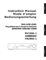
Regular Maintenance Service Recommendation
Although this unit is designed to withstand long-term use, the items listed below should be inspected regularly so that
the unit is kept in perfect working order. Use the hour meter to know when to conduct the inspections.
The VTR is a piece of precision-made equipment and, as such, it is recommended that the user enter into a
maintenance and inspection agreement to keep the unit operating free of trouble or failures. For further details,
please consult with your dealer.
Service life inspection
Cleaning
Cumulative operation time
(hours)
Inspection item
Transport system cleaning
Audio heads
Video heads
Cylinder unit
(L18-/L24-hour mode use)
500 1000 1500 2000 2500 3000 3500 4000 8000 12000
The above table merely serves to lay down general guidelines for the inspection of typical parts involved in regular
inspections. The timing of the inspections needs to be adjusted according to the VTR’s operating environment.
5
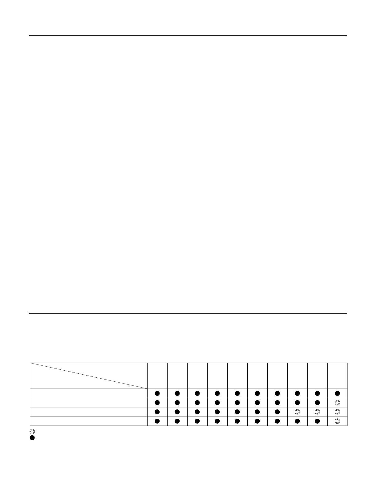
Routine & Regular Inspection Request
This unit is designed to withstand many hours of operation. Nevertheless, it is recommended that routine inspections
be conducted to help ensure trouble-free operation.
CAUTION
Do not forget to conduct the routine inspection with auto repeat recording.
Routine inspection procedure
q Set the power switches on the unit, video cameras,
TV monitor and other equipment connected in the
monitoring system to the ON position.
w Is the picture on the TV monitor OK?
e Are the date and time displayed on the TV monitor
correct?
11-15-01 6H
10:10:55
r Rewind the cassette tape, which was recorded on
the previous day, by an amount equivalent to a
count on the counter of several figures.
REW
t Press the TIME MODE button to set to the mode to
6H (6 hours).
Display
TIME MODE
y Press the PLAY button. The tape is played back by
an amount equivalent to a count on the counter of
several figures.
PLAY
u Is the playback image OK?
i Is there any problem with the recorded date and
time?
o Press the REC button.
REC
!0 Check the playback images which were recorded in
the 6-hour time mode.
!1 Upon completion of all the checks, set the unit to
the desired mode.
Action taken after routine inspections
In the unlikely event of a problem with the unit, turn off the power, take hold of the power plug and disconnect it from
the power outlet, and consult with the dealer from whom the unit was purchased.
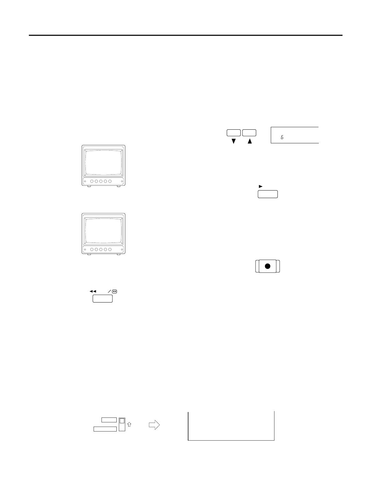
Regular inspections recommended
This unit has an hour meter which shows for how many hours the VTR has been used. When the MENU/REC LOCK
switch is set to MENU, Menu Screen 1 appears on the TV monitor, and the hour meter can be checked. Use the hour
meter as a rough guideline to cleaning or replacing the parts inside the unit. For further details, consult with your
dealer.
TV monitor
[HOUR METER]
00000H
MENU
OFF
REC LOCK
6
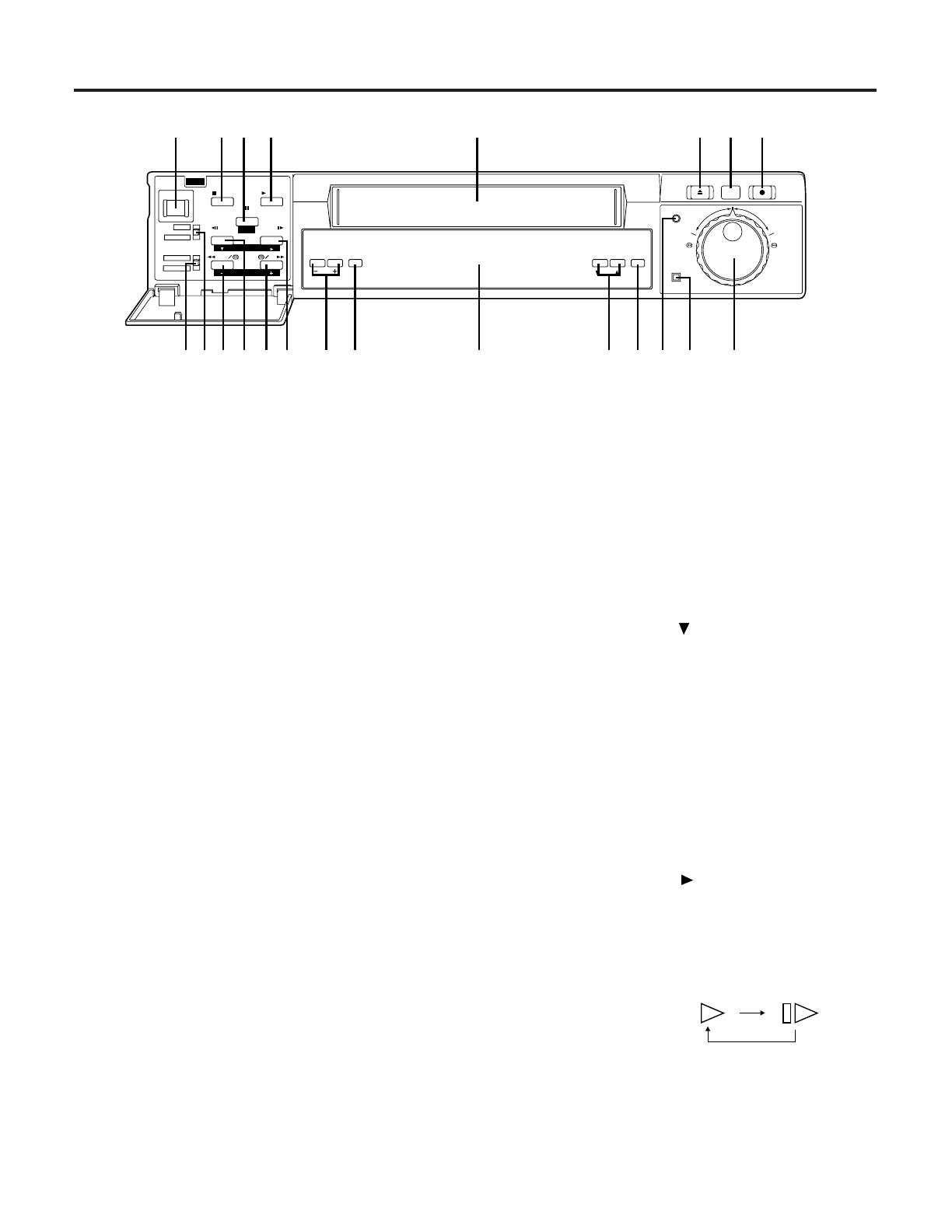
Parts and Their Functions
q POWER switch
The power is turned on when this switch is pressed.
When the switch is pressed again, the power is
turned off.
w STOP button
When this is pressed, the tape stops traveling.
e PAUSE/STILL (page) button
When this is pressed during recording, the tape
temporarily stops traveling. When pressed during
playback, the tape temporarily stops traveling, and
a still picture appears on the TV monitor. When
pressed again, the tape travel resumes.
The pages on the menu screen are advanced when
the button is pressed while a menu screen is
displayed.
r PLAY button
Playback starts when this button is pressed.
t Cassette holder
This is the loading slot for the video cassette.
y EJECT button
This is used to eject the video cassette.
u REC REVIEW button
When the button is pressed during recording, the
tape runs temporarily in the reverse direction, and
after the recorded section has been played back a
few seconds, the unit is returned to the recording
mode.
i REC button
Recording starts when this button is pressed.
o TIMER MODE switch
This is the operation switch for internal timer
recording or external timer recording.
INT TIMER: At the times set by the internal timer,
the power is automatically turned on
or off and recording starts or stops.
OFF:
When timer recording is not performed.
EXT TIMER: When the external power is turned on,
recording starts automatically.
TRACKING /
V-LOCK RESET
COUNTER /
REC
ALARM
REV
FWD
TIME MODE
SEARCH
EJECT
REC REVIEW
REC
PAGE
PAUSE/STILL
REV ADV
POWER
MENU
OFF
REC LOCK
INT TIMER
OFF
EXT TIMER
REW FF
FWD ADV
STOP PLAY
SHIFT
SET
qwer t yui
o!0!1 !2 !3 !4 !5 !6 !7 !8 !9 @0 @1 @2
!0 MENU/REC LOCK switch
When this switch is set to REC LOCK, the time
mode and operation buttons except for REC and
REC REVIEW as well as the power switch cannot
be operated while recording is in progress.
When it is set to MENU, the menu screen appears.
!1 REW (set –) button
When this button is pressed, the tape is rewound.
When it is kept depressed during playback, the
review mode is established. When a menu screen
is displayed, it is used to change an item (decre-
ment a value).
!2 Field REV ADV (shift ) button
When this is kept depressed during still-picture
playback, the picture is advanced field by field in
the reverse direction. When it is released, the still
picture reappears. When it is pressed while a menu
screen is displayed, the setting items move
downward.
!3 FF (set +) button
When this is pressed, the tape is fast forwarded.
When it is kept depressed during playback, the unit
is placed in the cue mode. When a menu screen is
displayed, it is used to change an item (increment a
value).
!4 Field FWD ADV (shift ) button
When this is kept depressed during still-picture
playback, the picture is advanced field by field in
the forward direction. When it is released, the still
picture reappears. When this is pressed during time
lapse mode (L18H – 240H) playback, Quais-V on/
off can be selected.
Operation mode display
Quasi-V off on
Dancing can be reduced.
When it is pressed while a menu screen is
displayed, the setting items move toward the right.
7
!5 Tracking (–, +)/V-LOCK button
These buttons are used to adjust the tracking. If
noise appears on the playback picture, press the
buttons to adjust the tracking is such a way that the
picture is made as clear as possible. When both
buttons are pressed together during 6-hour mode
playback, the tracking is adjusted automatically.
If the image shakes slightly in the vertical direction
during still picture, press V-LOCK buttons to reduce
the dancing.
Further, the time/date display position can be
adjusted during STOP and EJECT (see page 13).
!6 RESET button
When this button is pressed, the counter display is
reset to 0:00:00.
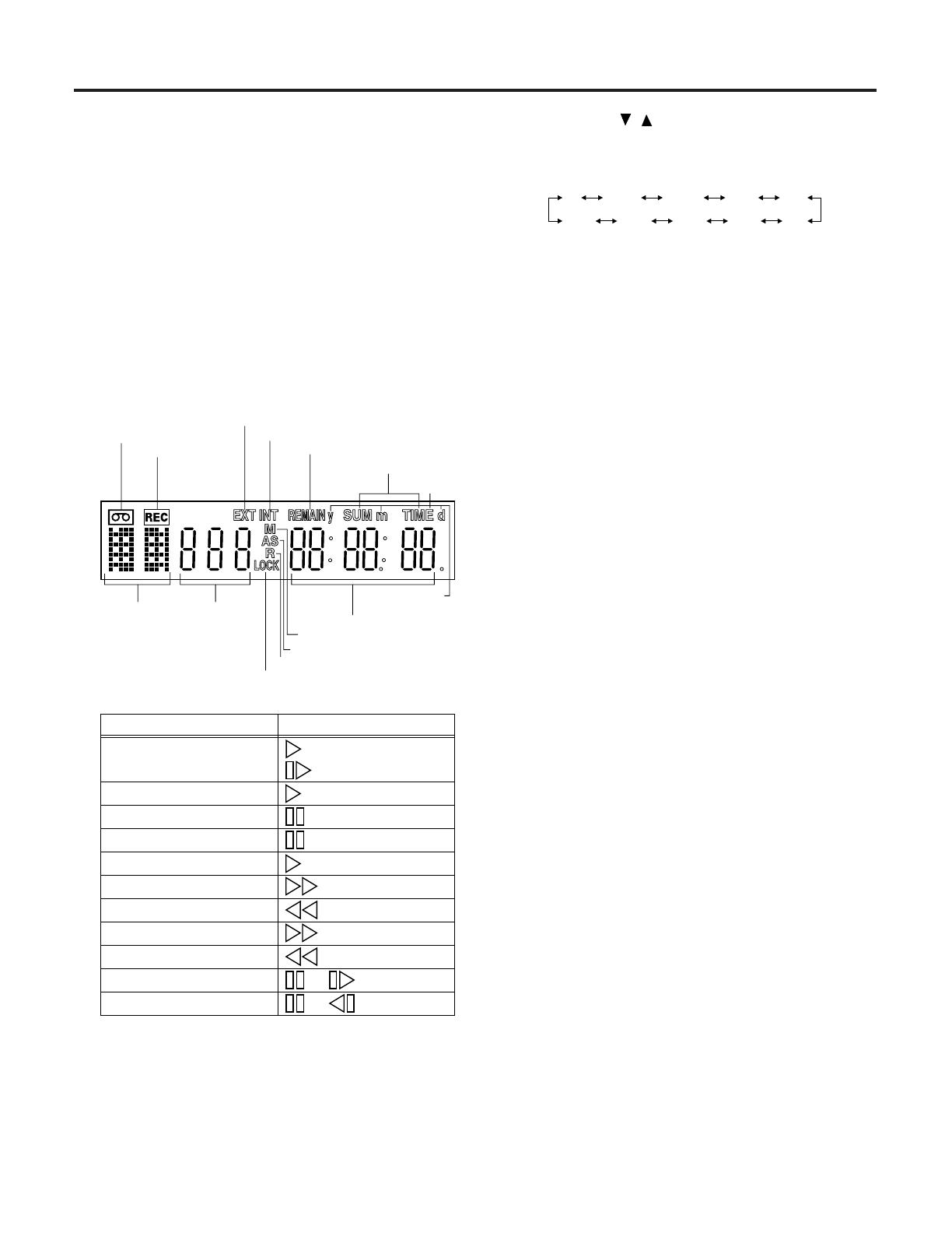
!7 Display panel
Recording display
VTR operation
mode display
Internal timer recording mode display
External timer recording mode display
Auto repeat recording display
Recording lock display
Cassete insertion display
Tape remaining display
Time mode
display
Memory stop mode display
Alarm search mode display
Time/counter
Time
display
Date setting
display
Daylight savings
display
• Operation mode displays
Recording
Cue
DisplayOperation mode
Playback
Still picture
Recording pause
Recording check
Fast forwarding
Rewinding
Review
Forward field advance
Reverse field advance
REC lamp lights.
REC lamp lights.
REC lamp lights.
(6H-240H) or
or (Flashing)
or (Flashing)
(L18H-240H)
• Error messages
An error code appears when trouble has occurred
during operation.
E-2: Trouble in video cassette insertion area
E-3: Trouble in video cassette tape loading area
E-4: Trouble in cylinder area
E-5: Trouble in tape transport area
d: Formation of condensation (dew)
!8 TIME MODE ( , ) buttons
These buttons are used to select the recording and
playback time mode. Each time this is pressed, the
time mode changes in the following sequence:
6 L18 L24 48 72
240 180 168 120 96
!9 COUNTER/SEARCH button
When this button is pressed, the display on the
display panel changes to time, counter, counter
memory, alarm search and number of repeat record-
ing display.
The “M” mark appears on the display panel in the
counter memory mode. When the tape is fast
forwarded or rewound in this mode, the counter will
automatically stop when 0:00:00 is approached. The
“AS” mark appears on the display panel in the alarm
search mode. When the tape is fast forwarded or
rewound in this mode, the unit is automatically set to
still-picture playback at the alarm recording section.
If the FF button or REW button is pressed during
playback with alarm search, the search will lock. (If
this button is pressed while the tape is being fast
forwarded or rewound, counter memory and alarm
search will not function.)
The “PAS.” mark appears in the display panel in the
number of repeat recordings display mode. The
number of repeat recordings is displayed only when
TAPE END in Menu Screen 4 is set to REPEAT.
The “__PAS” mark is displayed for settings other
than REPEAT.
@0 REC display lamp
This lamp lights while recording, recording/pause or
rec review is in progress. It goes off when recording
has finished.
@1 ALARM display lamp
This remains lighted while alarm recording is in
progress. It flashes when alarm recording ends.
@2 Search dial/jog dial
Search (outside ring) dial
When the outside ring of the search dial is turned,
the search mode is established. The tape can now
be reviewed or cued at up to 27 times the normal
playback speed. When the search dial is set to the
center click-stop position, the still-picture playback
mode is established.
Jog (inside ring) dial
When the search dial is set to the center click-stop
position, the jog mode is established.
When the inside ring is turned, the tape speed can
be varied within a range of –1 to +1 times the normal
playback speed. When the turning is stopped, the
still-picture playback mode is established.
• During search or jog playback, the picture may
appear in black and white or it may be distorted:
this is normal and not indicative of malfunctioning.
• No sound is heard during search or jog playback.

8
q Camera switching output connector
Camera switching output connector; connect it to
the sequential switcher.
w Audio input/output connectors
Audio input/output connectors (phono jacks)
e Video input/output connectors
Video input/output connectors (BNC); connect the
input connector to the video camera, etc. and the
output connector to the TV monitor, etc.
r AC IN connector
Connect the supplied power cord to an AC outlet.
t Alarm input connector
Alarm recording input connector; connect it to the
external sensor.
y COMMON terminal
u Alarm reset connector
Input connector for releasing alarm recording; a +4
to +14 V DC voltage is required.
i REC IN connector
Input connector for recording.
Note:
Do not input the signal to this connector while the
tape is rewinding automatically in the repeat mode.
o Tape end output connector
When the cassette tape comes to its end during
recording, the alarm device installed externally is
activated.
!0 WARNING/REC output connector
When trouble has occurred in the unit, the alarm
device installed externally is activated.
Error warning or recording low signal selected on
the menu screen 3 is output.
!1 GND terminal
This terminal is connected to the signal ground
terminal of the connected unit in order to reduce
noise. It is not connected to ground for safety
purposes.
!2 MIC input jack
Input jack (mini-jack) for an external microphone.
This jack has precedence when signals are supplied
simultaneously to this jack and the audio input
connectors.
!3 REMOTE control connector
For connecting the AG-A11 remote controller which
is available as an optional accessory.
!4 RS-232C connector
This connector enables basic operations of the unit
using a personal computer (etc.)
!5 Battery installation area
Install the battery in this area. See “Lithium Battery”
on page 2.
MIC
REMOTE
BATTERY
PUSH OPEN
CAMERA
IN
OUT
TAPE END OUT
WARNING/
REC OUT
REC IN
COMMON
ALARM RESET IN
ALARM IN
AUDIO
IN
OUT
VIEDO
GND
SW OUT
AC IN
RS-232C
q
rtyuio!0 !1 !2 !3 !5
!4
w
e
Parts and Their Functions
9
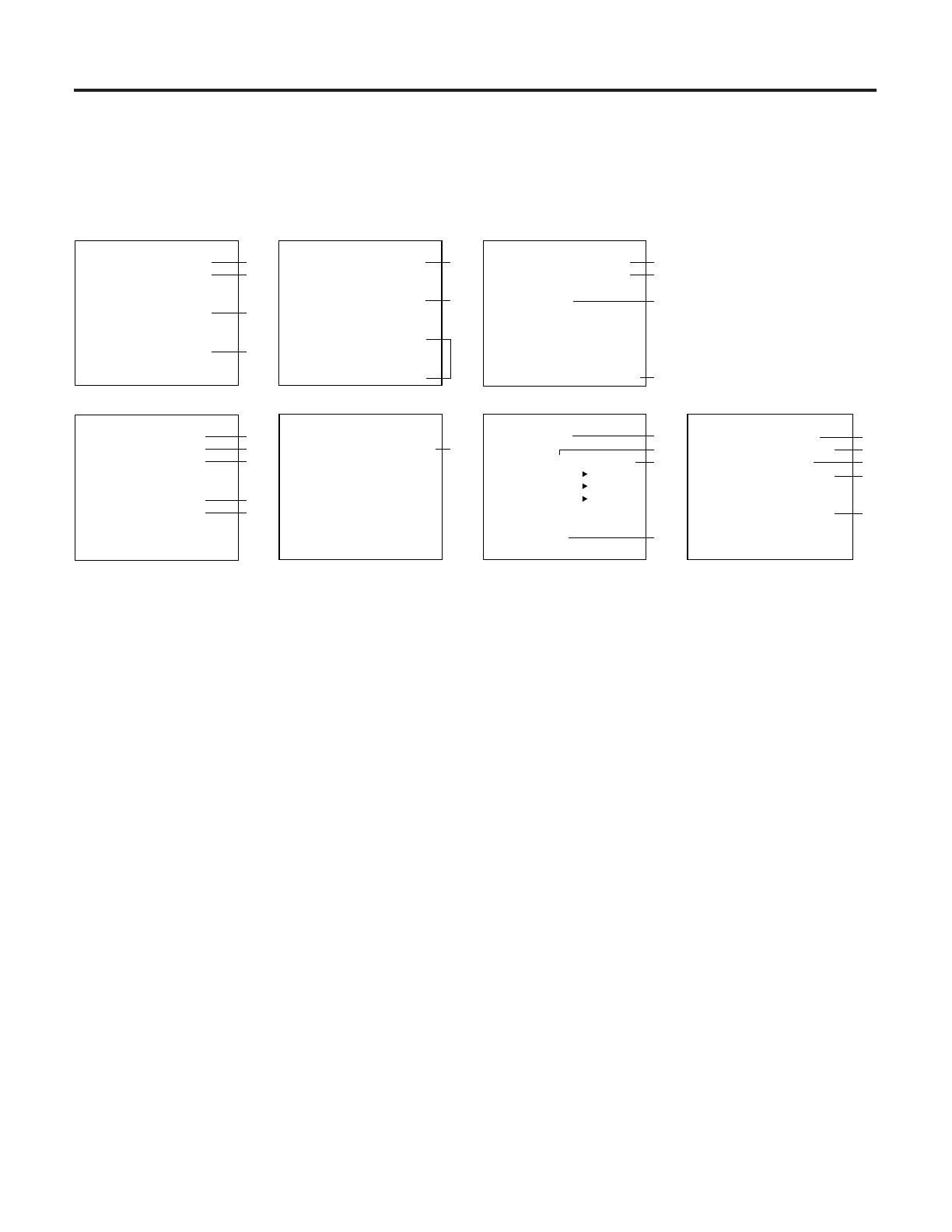
Menu Screens
One of the menu screens appears on the TV monitor when the MENU/REC LOCK switch is set to MENU. The display
returns to the regular screen when this switch is set to OFF.
•When a menu screen has appeared, the items are set using the page, shift and set buttons.
• Advance through the pages (“page up”) of the menu screen using the page button.
•Move the items (downward or toward the right) using the shift button.
• Change the items (increment or decrement the values) using the set button.
[TIME ADJUST] P1
1-01-2000 SAT
0:00:00
[REC LOCK]
MODE : OFF
[HOUR METER]
00000H
q
w
e
r
[DISPLAY] P2
POSITION : L-UPPER
[REC INDICATE]
NOT REC : CAMERA
[BUZZER]
ALARM : OFF
TAPE END : OFF
TAPE REMAIN : OFF
ERR WARN : OFF
t
y
u
[ALARM] P3
MODE : OFF
DURATION : 30SEC
[RECALL] -
-
-
-
[OUTPUT SELECT]
TERMINAL OUT : ERR WARN
i
o
!1
!0
[REC MODE] P4
REC T-MODE : OFF
TAPE IN : STOP
TAPE END : STOP
[VIDEO MODE]
MODE : AUTO
DETAIL : ON
!2
!3
!4
!5
!6
[INTERNAL TIMER REC] P5
[TIMER]START END T-M
SUN OFF
MON OFF
TUE OFF
WED OFF
THU OFF
FRI OFF
SAT OFF
DLY OFF
!7
[DAYLIGHT SAVINGS] P6
MODE : OFF
[START] [ END ]
WEEK :1ST-SUN LST-SUN
MONTH: 4 10
TIME : 2:00 2:00
[DIRECT SEARCH]
MODE : OFF
!8
!9
@0
@1
MENU SCREEN 1 MENU SCREEN 2 MENU SCREEN 3
MENU SCREEN 4
MENU SCREEN 5 MENU SCREEN 6
[RS-232C PARAMETERS] P7
BIT LENGTH : 7BIT
STOP BIT : STOP-1
PARITY : ODD
BAUD RATE : 9600BPS
[MENU LANGUAGE]
MODE : ENGLISH
@2
@3
@4
@5
@6
MENU SCREEN 7
MENU SCREEN 1
In addition to the date and time display and the recording mode lock setting which appear on the TV monitor, the hour
meter is displayed on Menu Screen 1.
q Date setting (see page 12)
w Time setting (see page 12)
e Recording mode lock
ON: LOCK on the front display tube flashes up, and
all operations except for REC and REC REVIEW
are prohibited while recording is in progress.
r Hour meter (see page 5)
This indicates the unit’s total operation time (the
cumulative total for the cylinder rotation time).
MENU SCREEN 2
The time/date display position, monitor screen blue display and buzzer settings are performed on Menu Screen 2.
remaining before the end is reached in the
recording mode.
ERR WARN: The buzzer sounds when the unit is
set to the warning status.
To release the buzzer:
ALARM: Release alarm recording.
TAPE END: Tr ansfer the mode from the tape end or
press the STOP button.
TAPE REMAIN: Transfer the mode (but not to
PAUSE or REC REVIEW) from the recording mode
or press the REC button.
ERR WARN: Release the warning status.
• When TAPE END or TAPE REMAIN has been set to OFF, the
buzzer will not sound; however, the REMAIN display will
remain lit or flashing.
• When TAPE END or TAPE REMAIN has been set to ON,
REMAIN lights or flashes on the display tube at the same time
as buzzer sounds.
They cease flashing when the buzzer is released.
Note:
The remaining tape is displayed only with T-120 and T-160
tapes. It is not displayed when any other tapes are used.
t Display position selection (see page 13)
This selects the position where the date and time
are to be displayed on the TV monitor.
(L-UPPER ↔ R-UPPER ↔ L-BOTTOM ↔
R-BOTTOM ↔ CENTER ↔ OFF ↔ L-UPPER...)
y Blue display
This sets a blue display on the monitor screen at all
times except while recording or playback is in progress.
BLUE: The display on the monitor screen is blue at all
times except while recording or playback is in progress.
CAMERA: The pictures from the video input con-
nector are shown on the monitor screen at all times
except while playback is in progress.
u Setting of the buzzer sound
ALARM: The buzzer sounds once alarm recording
is performed.
TAPE END: When the tape end is reached in the
recording mode, the buzzer sounds while the tape is
at the end.
TAPE REMAIN: The buzzer sounds when there is
only about 3% (with a T-120/T-160 tape) of the tape

10
Menu Screens
MENU SCREEN 3
The alarm recording mode and terminal output are set on Menu Screen 3.
i Alarm recording mode selection (see page 20)
The recording mode in the event of an alarm input
is selected. (OFF ↔ ALARM)
ALARM: When there is an alarm input during
recording in the time lapse mode, the recording time
mode is switched to 6H (alarm recording) and the
details of the alarm status are recorded faithfully.
OFF: Alarm recording is not possible even when an
alarm signal is input during recording.
o Alarm recording duration setting
This sets the time elapsing from the start of alarm
recording until its end. (30SEC ↔ 1MIN ↔ 2MIN ↔
3MIN ↔ 5MIN ↔ 10MIN ↔ CONTINUE ↔
MANUAL ↔ 30SEC...)
CONTINUE
: Alarm recording continues until the
tape end.
MANUAL: Alarm recording is performed while the
alarm input continues.
!0 Alarm recall (see page 20)
This checks the date/time (up to 4) of the alarm
signals.
!1 Terminal connector output signal setting
ERR WARN: When trouble has occurred in the unit
(AUTO OFF), the LOW signal is output.
REC: The LOW signal is output during recording.
MENU SCREEN 4
Recording mode and video output are selected on Menu Screen 4.
!2 Recording time mode selection (see page 14)
When recording starts, the set time mode is always
established.
(OFF ↔ 6H ↔ L18H ↔ L24H ↔ 48H ↔ 72H ↔
96H ↔ 120H ↔ 168H ↔ 180H ↔ 240H ↔ OFF...)
OFF: Any time mode can be set using the TIME
MODE button on the front panel. It can be changed
even while recording is in progress.
6H: 6-hour mode (compatible with the standard
mode of ordinary VTR’s).
L18H/L24H: L18-/L24-hour mode (linear slow
recording).
48H/72H/96H/120H/168H/180H/240H
: 48-/72-/96-/
120-/168-/180-/240-hour mode (time lapse recording).
!3 Selection of VTR operation when cassette is
inserted
STOP: Stop mode
REC: Simply by inserting the cassette tape, record-
ing is started automatically.
REW REC: When the cassette is inserted, it is first
rewound to the start of the tape and then recording
is started automatically.
!4 Selection of operation when tape end is de-
tected during recording (see page 18)
STOP: Stop mode
REW: The tape is automatically rewound to the
start where it stops.
REPEAT: The tape is automatically rewound to the
start, and recording is repeated.
EJECT: The tape is ejected.
!5 Video signal mode
This selects the operation of the color/black-and-
white automatic selector circuit.
AUTO: The circuit automatically identifies the type
of video input or playback signals, and selects the
color or black-and-white mode accordingly.
COLOR: The color mode is forcibly established.
B_W: The black-and-white mode is forcibly
established.
!6 Playback picture quality selection
The detail of the playback images can be
emphasized.
OFF: Regular mode
ON: The playback picture has emphasized outlines.
MENU SCREEN 5
The internal timer recording modes are set on Menu Screen 5.
!7 Internal timer recording mode setting (see page
16)
This sets the weekly timer or daily timer recording
mode. (OFF/ON)
OFF: Internal timer recording is not set.
ON: Internal timer recording is set. (The start and
stop times are set.)
Note:
Internal timer recording does not operate when the
date and time have not been set.

11
MENU SCREEN 6
The daylight savings mode and search dial and jog dial operation mode are set on Menu Screen 6.
!8 Selecting the daylight savings mode
Select the daylight savings mode.
ON: The daylight savings mode is selected.
OFF: The daylight savings mode is not selected.
!9 Setting the start time for the daylight savings
mode
Set the week, month and hour at which the daylight
savings mode is to start.
WEEK: Select 1ST, 2ND, 3RD, 4TH or LST (last)
and one of SUN through SAT.
MONTH: Select the starting month (1 – 12).
TIME: Select the start time (1:00 – 22:00)*.
Do not adjust the time setting between 23:00 and
1:00 during the daylight savings period.
@0 Setting the end time for the daylight savings
mode
Set the week, month and hour at which the daylight
savings mode is to end.
WEEK: Select 1ST, 2ND, 3RD, 4TH or LST (last)
and one of SUN through SAT.
MONTH: Select the ending month (1 – 12).
TIME: Select the end time (1:00 – 22:00)*.
@1 Search dial and jog dial direct operation mode
Set the operation mode when the search dial or jog
dial is to be used from another mode.
ON: The dial can be operated directly during STOP
and STILL.
OFF: The dial can be operated after the STILL
button is pressed.
* Minutes are for reference only and cannot be adjusted.
MENU SCREEN 7
The RS-232C parameters are set on Menu Screen 7.
@2 Setting the bit length (7BIT/8BIT)
@3 Setting the stop bit (STOP-1/STOP-2)
@4 Setting the parity bit (ODD/EVEN/NON)
@5 Setting the baud rate (4800BPS/9600BPS)
@6
Selection of the menu display language
(ENGLISH/FRANCAIS)
* The underline denotes the factory setting.
CAUTIONS:
• The menu screens are not displayed while the unit is playing back a tape.
•While the unit is recording, the contents of Menu Screen 1 can be changed; however, Menu Screens 2 to 7 are for
reference only and therefore cannot be changed.

12
Date and Time Settings
This unit comes with a time/date generator which enables the date and time to be superimposed on the recording.
When the power is switched on, the date, time of the day and time mode are displayed (in the case of a regular
screen).
1 0
-
1 0
-
0 1 6 H
1 0
:
1 4
:
3 0 A
Date:
The date appears as month/day/year.
Time mode:
This is set by pressing the TIME MODE button. It
flashes unless recording is in progress.
Time:
The 24-hour system is used.
Alarm display:
This appears during alarm recording.
q
w
e
r
TV monitor
Date
1
Time mode
2
Time
3
Alarm display
4
PAGE
PAUSE/STILL
REV ADV
POWER
MENU
OFF
REC LOCK
INT TIMER
OFF
EXT TIMER
REW FF
FWD ADV
STOP PLAY
SHIFT
SET
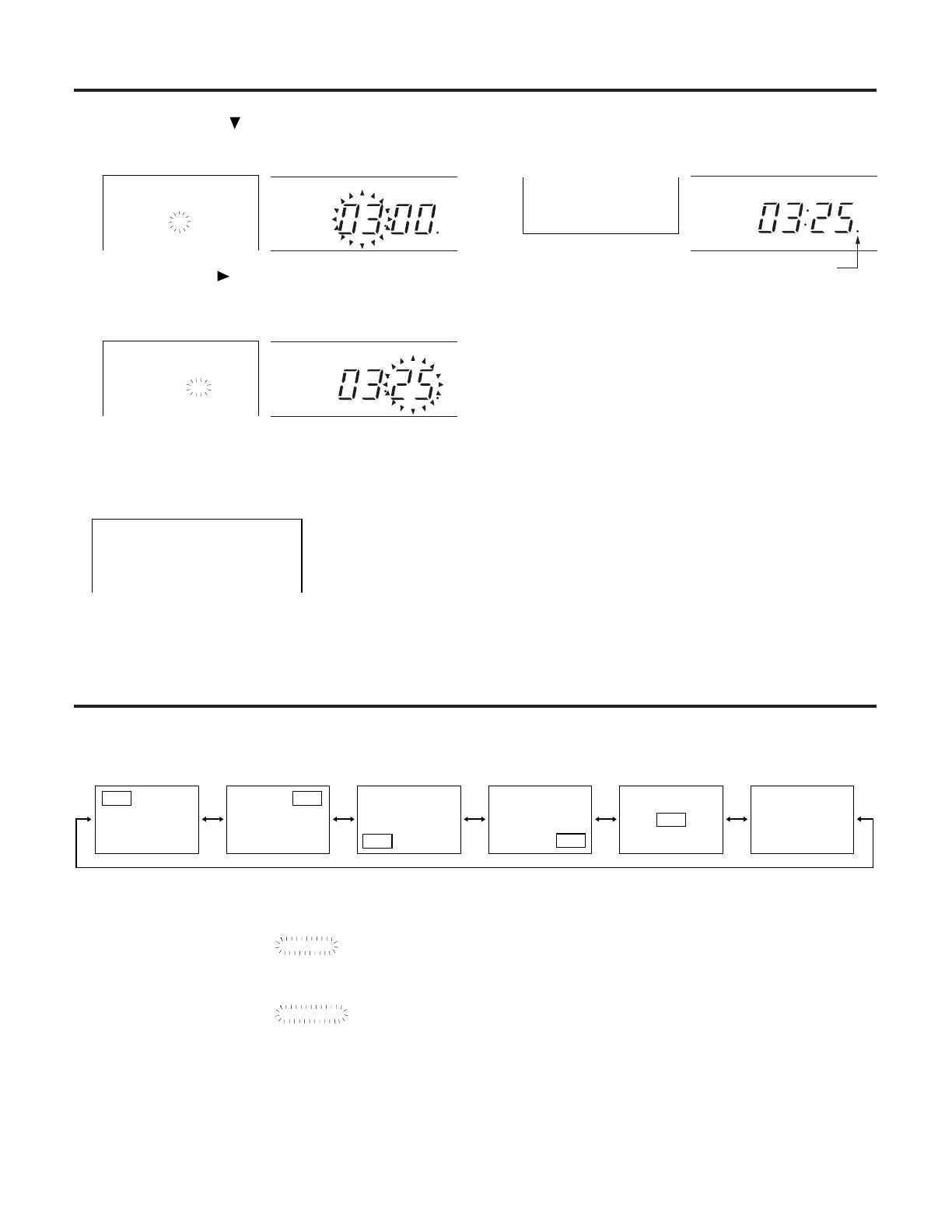
Example: Setting the date and time to Saturday, March 3, 2001 at 3:25.
The time mode is set to 48 hours.
When the shift ( ) button is pressed, the month
digits flash.
Press the SET (+, –) buttons to set the month to
“3”.
When the shift ( ) button is pressed, the day digits
flash.
Press the SET (+, –) buttons to set the day to “03”.
• The year can be set from 2000 to 2079.
Set the MENU/REC LOCK switch to MENU. Menu
Screen 1 appears, and the year digits flash.
Press the SET (+, –) buttons to set the year to
“2001”.
[TIME ADJUST] P1
1-01-2000 SAT
0:00:00
m
m
m
d
d
d
Monitor display Display area
q
w
[TIME ADJUST] P1
1-01-2001 MON
0:00:00
[TIME ADJUST] P1
3-01-2001 THU
0:00:00
e
r
[TIME ADJUST] P1
3-03-2001 SAT
0:00:00
m
d
13
TIME
TIME
TIME
When the shift ( ) button is pressed, the hour
digits flash.
Press the SET (+, –) buttons to set the hour to “3”.
When the shift ( ) button is pressed, minute digits
flash.
Press the SET (+, –) buttons to set the minutes to
“25”.
t
y
[TIME ADJUST] P1
3-03-2001 SAT
3:00:00
[TIME ADJUST] P1
3-03-2001 SAT
3:25:00
When the MENU/REC LOCK switch is set to OFF,
the clock automatically starts running from time and
date set.
Flashing
For the seconds, “00” is set.
Even when the switch is set to MENU, the time will
keep advancing if it has not been changed.
u
3-03-01 48H
03:25:00
•To clear the date and time display, set POSITION under (DISPLAY) on Menu Screen 2 to OFF.
• Even if the power should fail for a period of up to one week, the date, time and other display time mode data are
stored in the memory (but only if power has been supplied continuously to the unit for 3 or more days).
When the unit has just been purchased or when it has not been used for along time, the data is not stored in the
memory and the display shown below appears.
[TIME ADJUST] P1
1-01-2000 SAT
0:00:00
• For the date setting, the unit automatically adjusts for leap years.
• Due to temperature fluctuations and other factors, the clock time may run fast or slow with a monthly error of up to
±60 seconds. This is not indicative of malfunctioning. Reset the time at regular intervals.
Time/Date Display Position
The position of the date and time displays on the TV monitor changes as shown below when (DISPLAY) on Menu
Screen 2 is changed.
Top left corner Top right corner Bottom left corner No displayCenterBottom right corner
Set the MENU/REC LOCK switch to MENU to
display to menu screens. Press the page button to
display Menu Screen 2 on the TV monitor.
POSITION : L-UPPER
Press the set (+, –) buttons to position the display
as desired.
POSITION : L-BOTTOM
q
w
Upon completion of the settings, set the MENU/
REC LOCK switch to OFF. The regular screen is
restored, and the date and time appear at the
selected position.
e
TIME/DATE display position adjustment function
When the unit is in STOP or EJECT mode, the position of the displayed time/date can be adjusted by pressing the
TRACKING (–) or TRACKING (+) button.
• Pressing the TRACKING (–) button moves the position vertically. (Pressing the button 3 times will return the display
to its original position.)
• Pressing the TRACKING (+) button moves the position horizontally. (Pressing the button 3 times will return the
display to its original position.)
• Pressing the (–) and (+) buttons simultaneously will return the display to its original position (factory setting).
When the time is reset to “0:00:00” as described, check the menu
settings. If any of the settings are incorrect, please set them again.
14
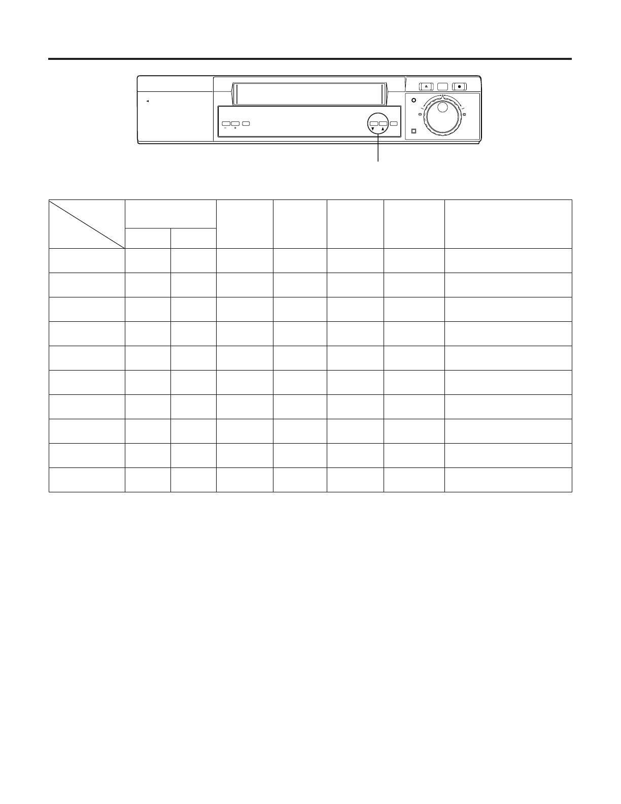
Time Mode Selection
TIME MODE button
TRACKING /
V-LOCK RESET
PULL OPEN
COUNTER /
TIME MODE
SEARCH
REC
ALARM
EJECT
REC REVIEW
REC
REV
FWD
Refer to the table given below to select the mode that suits the intended purpose of use.
6 hours 861/60 60 Yes 1/30
L18 hours 24 18 0.05 20 Yes 0.05
L24 hours 40 24 0.083 12 Yes 0.083
48 hours —* 48 0.150 6.67 No 0.150
72 hours —* 72 0.217 4.62 No 0.217
96 hours —* 96 0.283 3.53 No 0.283
120 hours —* 120 0.350 2.86 No 0.35
168 hours —* 168 0.483 2.07 No 0.483
180 hours —* 180 0.517 1.94 No 0.517
240 hours —* 240 0.683 1.46 No 0.683
Tape type
Recordable time
(hours)
T-160 T-120
Mode
Pictures
per
second
(fields)
Video
recording
interval
(sec.)
Sound
recording
Camera
switching
interval
(sec.)
Tape replacement standard
(recording times)
————
50
50
25
20
20
15
10
10
10
*: Avoid using 160-minute tapes with any of the modes from 48 hours to 240 hours.
Notes on operation
• This unit is designed with the T-120 cassette tape as a reference.
• Recording is possible up to 240 hours with this unit when the T-120 cassette tape is used.
• Depending on the type of video cassette used, the recordable time will differ.
• Depending on the type of tape used, it may be possible to record for slightly longer than the times shown in the “Recordable
time” column in the table above.
For example, 30 hours of recording are possible when a 120-minute tape is used with L24-hour mode.
• Sound can be recorded in 6, L18 and L24 hour modes.
• The L18-hour to 240-hour modes are time lapse modes. Pictures are recorded with frames skipped to enable lengthy recording
and playback.
•A tape recorded in a time lapse (L18-hour to 240-hour) mode can be played back in quick motion in the 6-hour mode.
•A tape recorded in the 6-hour mode can be played back in slow motion using the time lapse (L18-hour to 240-hour) mode.
•A tape recorded in the 2-hour mode on a different VTR can be played back in the 2-hour mode.
•Tapes recorded on this machine cannot be played back other VHS video recorder as they are not compatible.
• Recording and playback in the 6H, L18H and L24H time modes with this unit are in the same format as in the 8H, 24H and 40H
time modes with the AG-RT650. The time mode display differs from the AG-RT650.
Selecting the cassette tape
The unit is designed as a product required to exhibit high reliability in surveillance, security, monitoring, etc. In order to maintain its
recording reliability, it is recommended that the video tapes listed below be used.
<VHS tapes> • T-160 • T-90 • T-30
•T-120 • T-60
•Avoid using 180-minute tapes with this unit.

15
Recording Procedure
q Switch on the power to the connected equipment.
w Adjust so that the images of the video cameras
appear properly on the TV monitor.
e Check that the date and time displayed on the TV
monitor have been adjusted properly.
r Insert a cassette tape into the unit after checking
that the tab on the cassette is intact.
t Set the timer recording, auto repeat recording, alarm
recording, restoration-of-power-after-failure record-
ing or other recording function.
y Select the time mode for the recording.
u Press the REC button.
Notes on operation
• If the PAUSE/STILL button is pressed during recording, the unit is set to the pause mode, and after about 5 minutes
in this mode it is transferred to the stop mode.
• Neat frame-to-frame continuity is not achieved if the recording mode is set again after the PAUSE/STILL button is
pressed during recording.
•When the MENU/REC LOCK switch has been set to OFF, other operations can be performed during recording.
•When restoration-of-power-after-failure recording is performed, recording can be continued in the same time mode
even if the power should fail provided that the power is restored within about one week. (This applies only if the
power has been supplied continuously for 3 or more days.)
•When performing auto repeat recording or timer recording, do not neglect to conduct the routine inspections.
•When recording images from a black-and-white camera, set the video signal mode on Menu Screen 4 to B_W.
• Remove the cassette tape if the unit is to be left standing for a prolonged period of time.
•When the power supply is interrupted during recording (with the power switch still ON), a non-recorded portion will
be made in the beginning of the tape travel, or the tape will be over-recorded at its ending section. But this is not a
malfunction.
Tips For Better Recording
In order to ensure greater reliability in monitoring, surveillance and other continuous operations lasting many hours,
this unit comes with some safety functions for recording. Read the following descriptions of these functions before
proceeding to operate the unit.
Recording Mode Lock
There are two ways, as described below, to maintain
the recording mode during recording by disabling the
operations of the power switch as well as the TIME
MODE and operation buttons.
q Set the MENU/REC LOCK switch to REC LOCK.
w Set REC LOCK on Menu Screen 1 to ON. (See
Note)
The following button and connectors are operational
during recording even if the MENU/REC LOCK switch is
set to REC LOCK.
• Alarm input connector, alarm reset connector
• REC REVIEW
Recording Check
When the REC CHECK button is pressed during
recording, the tape runs temporarily in the reverse
direction, and the recorded section is played back. This
function can be used to check the daily operation of the
equipment in the system.
Restoration-of-Power-After-Failure
Recording
When a power failure has occurred during recording,
the unit automatically starts recording if the power is
restored within approximately one week.
•When the power fails, the tape “losing” safety pro-
tection function is activated to protect the video heads
and video tape.
Before power is restored After power is restored
Stop, play, fast forward Stop mode is established.
Recording
Recording mode is
established.
Auto rewind
Auto rewind during
auto repeat recording
Unit is returned to the
mode applying before the
power failed.
•
•
•
•
Notes:
•When the power cord has come out of the socket or a
power failure has occurred, no operations will be
acknowledged for about 30 seconds after the power
has been restored: this is to protect the tape.
• Once the recording mode is established, recording
cannot be released until REC LOCK on Menu Screen
1 is set OFF.

16
Timer Recording
There are two methods of timer recording: one uses the internal timer and the other uses an external timer.
Internal Timer Recording
Start time and stop time
Bear in mind the following points when setting these
times.
•When the stop time is set later than the start time:
Recording will commence at the start time on the day
concerned and stop at the end time on the same day.
Example: 8:30 → 17:00
•When the start time is set later than the stop time
or the start time and stop time for weekly record-
ing (weekly timer) are the same:
Recording starts at the start time on the day con-
cerned and ends at the stop time on the following day.
Example: 17:00 → 8:30
•When the start time and stop time are the same
(for weekly recording):
Recording starts at 8:30 on the day concerned and
ends at 8:30 on the following day.
Example: 8:30 → 8:30
To record for an entire day, set the start time and stop
time to 0:00.
•Weekly recording (weekly timer) can be set by the
day of the week.
•When (INTERNAL TIMER REC) on Menu Screen
5 is set to OFF for both the weekly timer and daily
recording (daily timer), nothing appears for the
start or stop time. Timer recording is considered
not to be set.
Internal timer recording operation
VTR operations after the settings
• The unit’s power is turned off, and even if other but-
tons are pressed, their operations are not accepted.
•When the start time and stop time have not been set,
INT flashes on the display.
Releasing the internal timer mode
Set the TIMER MODE switch to OFF to clear INT on the
display.
Note:
• Since it takes some moments for recording to start,
set the start time for timer recording one minute
earlier.
[INTERNAL TIMER REC] P5
[TIMER]START END T-M
SUN OFF
MON OFF
TUE OFF
WED OFF
THU OFF
FRI OFF
SAT OFF
DLY OFF
Check that a video cassette with its tab intact has
been inserted.
Check that the TV monitor shows the correct pres-
ent time.
Set the MENU/REC LOCK switch to MENU to
display the menu screens. Press the page button
so that the INTERNAL TIMER REC timer setting
screen appears on the TV monitor.
q
w
e
Set the operation times of the internal timer.
• For details on the settings, refer to the sections
on “Daily timer” or “Weekly timer.” (See page 17.)
Upon completion of the settings, set the MENU/
REC LOCK switch to OFF. The regular screen is
restored.
Set the TIMER MODE switch to INT TIMER so that
INT lights on the display.
When the time and date for Menu Screen 1 have
not been set, a cassette has not been inserted, the
timer has not been set, or when a cassette with a
broken out tab has been inserted, the buzzer
sounds and INT flashes on the display.
r
t
y

17
Daily Recording (Daily Timer)/Weekly Recording (Weekly Timer)
Example: When recording from 8:30 to 12:00 from Sunday through
Thursday and from 9:00 to 12:00 on Fridays and Saturdays
SUN ON 0:00 0:00
SUN ON 8:00 0:00
SUN ON 8:00 0:00
SUN ON 8:30 0:00
SUN ON 8:30 0:00
SUN ON 8:30 12:00
Check that OFF or ON for Sunday (SUN) is
flashing. If the setting is OFF, press the set (+, –)
buttons to display ON.
When the shift ( ) button is pressed, the setting
moves to the start time and the “hour” digits flash.
Press the set (+, –) buttons to display “8.”
When the shift ( ) button is pressed, the “minutes”
digits flash.
Press the set (+, –) buttons to display “30”.
q
w
e
r
t
[INTERNAL TIMER REC] P5
[TIMER]START END T-M
SUN OFF
MON OFF
When the shift ( ) button is pressed, the “hour”
digits flash.
Press the set (+, –) buttons to display “12”.
When the shift ( ) button is pressed, the “minutes”
digits flash.
Press the set (+, –) buttons to display “00”.
Press the shift ( ) button to set the recording time
mode (6, L18, L24, 48, 72, 96, 120, 168, 180 and
240 hour mode). When the shift ( ) button is
pressed, the MON is flashing.
Following the same procedure in steps 1 to 10,
display the start time of “8:30” and stop time of
“12:00” from Monday (MON) through Thursday
(THU). Following the above procedure, set the
times for Friday (FRI) and Saturday (SAT) as well.
In this way, the timer operation times have been
set for each day of the week.
The settings for daily recording (daily timer) are
also performed following the same steps 1 to 10.
y
u
i
o
!0
!1
SUN ON 8:30 12:00
SUN ON 8:30 12:00
SUN ON 8:30 12:00 24
• The setting shown on the screen at the left translates into the weekly and daily timer recording combinations shown
below which, in turn, means that the actual recording time on the tape is shown at the bottom.
[INTERNAL TIMER REC] P5
[TIMER]START END T-M
SUN ON 8:30 8:00 L24
MON ON 12:00 14:00 L18
TUE OFF
WED OFF
THU ON 14:00 23:00 L18
FRI OFF
SAT ON 12:00 8:00 L24
DLY ON 18:00 8:00 L18
Weekly
Timer
Daily
Timer
Actual
Recording
Time
Sunday Monday Tuesday Wednesday Thursday Friday Saturday
8:00 8:00
8:00 8:00
8:00
18:00
14:00
12:00
12:00
14:00
8:00 18:00 8:00
18:00 8:00
14:00 8:00
18:00 8:00 12:00
14:00 23:00 12:00
18:00
L24H
L24H L24H
L18HL18H
L24H L18HL18H L18H L18H L18H
L18H L18H L24H
8:30
8:00 8:30
L24H
L18H
• The day of the week time settings are displayed, enabling the settings to be checked for each day of the week.
• Proceed with the setting with due consideration given to the total recording time since a 120-minute tape is long
enough to provide recording for up to 240 hours only.
18
Timer Recording
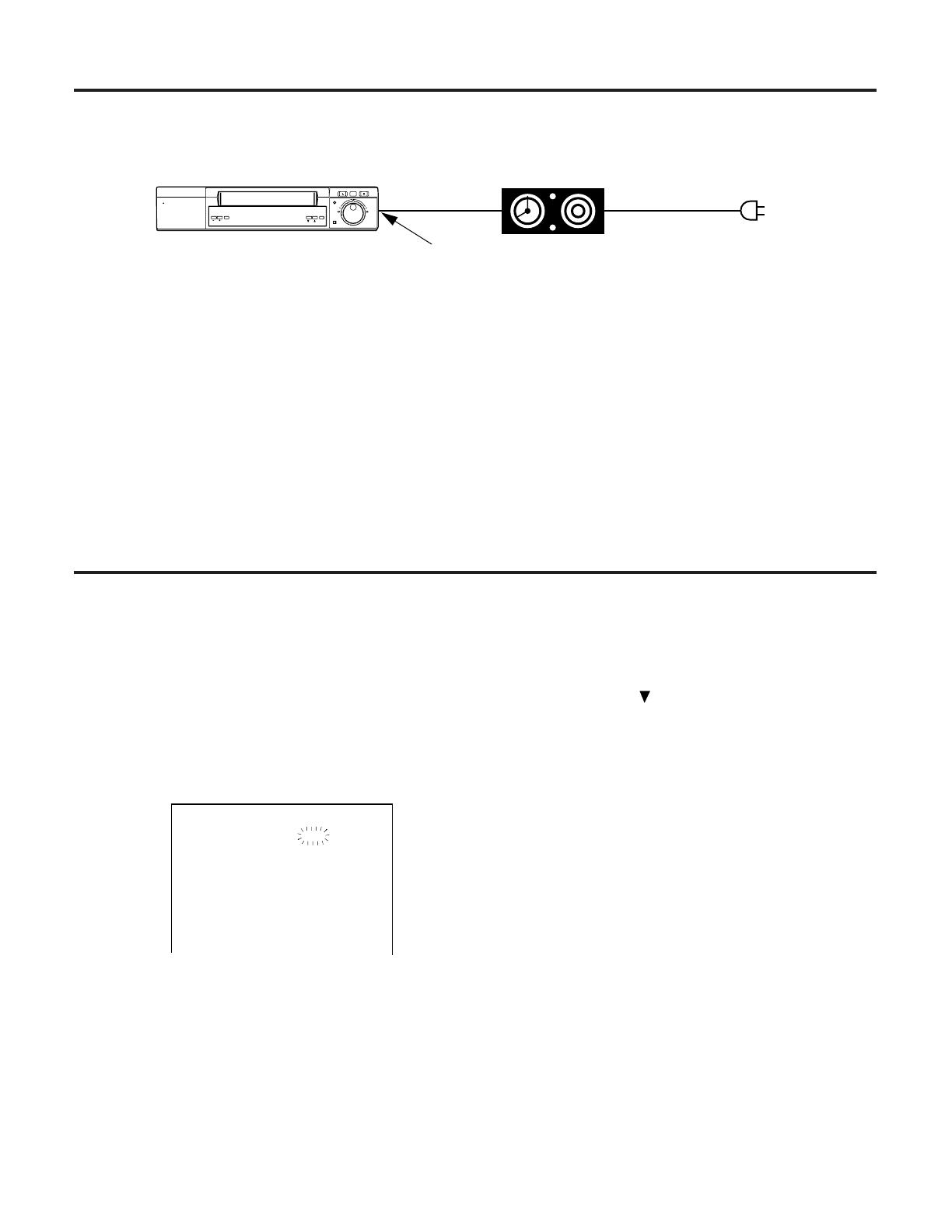
External Timer Recording
The unit can be made to record using an external timer to turn on its power.
(Audio timer available from dealer)
Power Cord
To AC IN
Timer
TRACKING /
V-LOCK RESET
PULL OPEN
COUNTER /
TIME MODE
SEARCH
REC
ALARM
EJECT
REC REVIEW
REC
REV
FWD
External timer recording operations
q Check that a video cassette with its tab intact has
been inserted.
• If the video cassette tape has not been inserted or if its accidental erasure prevention tab has been broken, EXT will
flash on the display, and external timer recording cannot be conducted.
• Since it takes some moments for recording to start, set the start time for timer recording one minute earlier.
• Depending on the tape position, some of the images at the start of the external timer recording may not be recorded
or may record over the images at the end of the previous external timer recording.
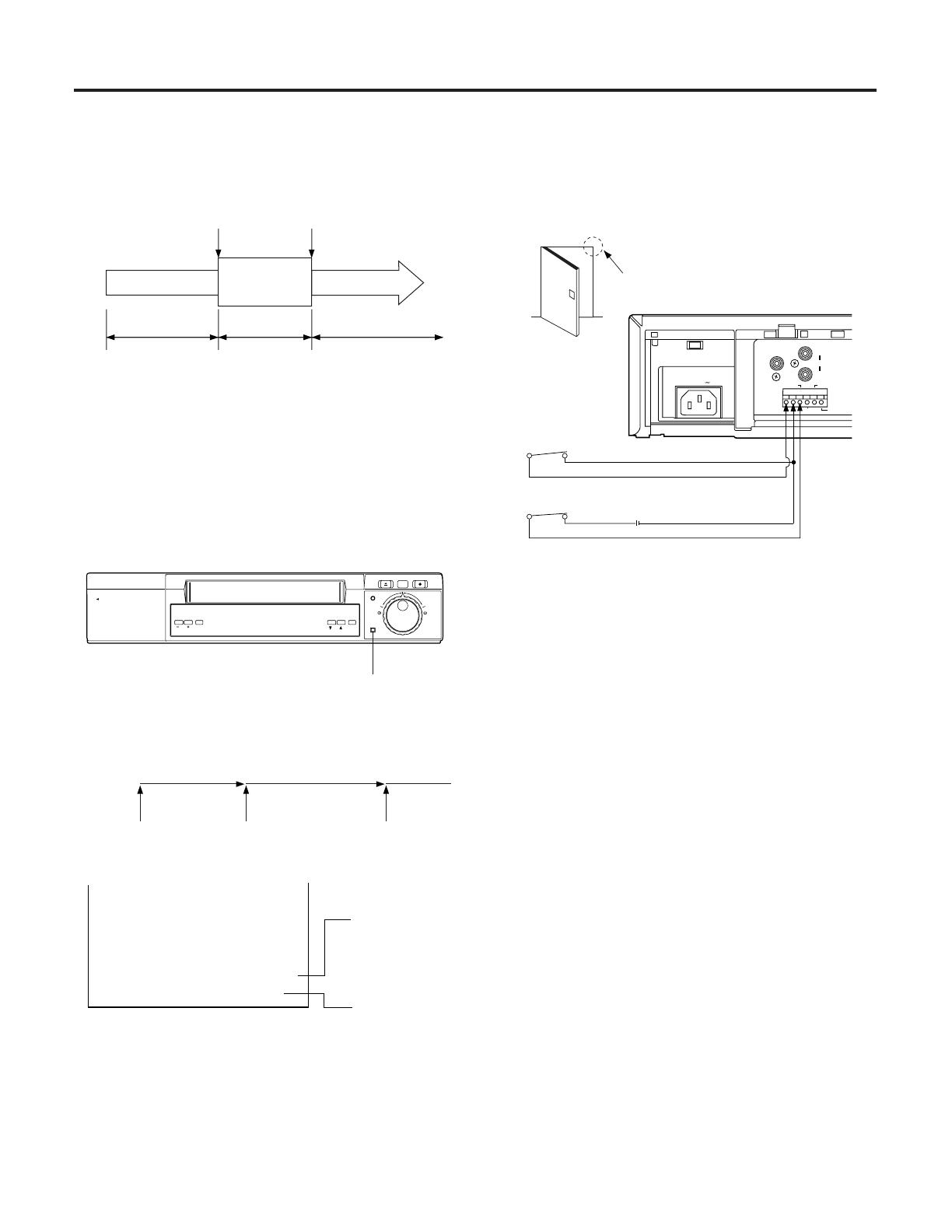
Auto Repeat Recording/Auto Rewinding
Auto repeat recording: This function automatically rewinds the cassette tape when its end is detected in the
recording mode, and it repeats recording from the start of the tape.
Auto rewinding: This function automatically rewinds the tape to the start when the tape end is detected in the
recording mode.
Check that a video cassette with its tab intact has
been inserted.
Set the MENU/REC LOCK switch to MENU to
display the menu screens. Press the page button to
display Menu Screen 4 on the TV monitor.
q
w
Press the shift ( ) button to move the flashing to
TAPE END.
Press the set (+ or –) button to display REPEAT for
auto repeat recording or REW for auto rewinding.
“R” lights on the display.
• If auto rewinding has been selected, “R” is
cleared.
Upon completion of the settings, set the MENU/
REC LOCK switch to OFF. The regular screen is
restored.
e
r
t
[REC MODE] P4
REC T-MODE : OFF
TAPE IN : STOP
TAPE END : STOP
[VIDEO MODE]
MODE : AUTO
DETAIL : ON
Notes of operation
•When auto repeat recording is to be performed, do not neglect the routine inspections. Since the image deteriorates
when the same tape is used over and over again for auto repeat recording, replace the tape with a new one after
about 50 recordings. When the tape is removed and then reinserted, the number changes to 01.
• Alarm signals are not accepted during auto rewinding, and so alarm recording is not performed.
• If an alarm signal is supplied during auto repeat recording, the alarm recording mode is established. If the tape then
reaches its end, auto repeat recording is performed but alarm recording is released.
• If TAPE END on Menu Screen 4 has been set to REPEAT, use a DURATION other than MANUAL.
•When the power cord has come out of the socket or a power failure has occurred, no operations will be
acknowledged for about 30 seconds after the power has been restored: this is to protect the tape.
w Set the TIMER MODE switch to EXT TIMER so that
EXT lights on the display. At the set time, power is
supplied from the external timer and the unit is set
to the recording mode.
19
Alarm Recording (Emergency Recording)
When an emergency occurs at the monitoring site during prolonged monitoring and recording, the alarm function is
automatically triggered, and alarm recording is performed.
Principle of Alarm Recording
Alarm input Alarm reset input
Time lapse mode Alarm mode Time lapse mode
Tape end
Tape start
L18 to 240 hours 6 hours L18 to 240 hours
•When an alarm signal is supplied by an alarm sensor
(door or intercom switch, etc.) during recording in a
time lapse mode, the recording speed is switched to
the 6-hour mode and the details of the state of emer-
gency are faithfully recorded.
Alarm and Display Methods during
Alarm Recording
ALARM display lamp
REC
ALARM
EJECT
REC REVIEW
REC
REV
FWD
TRACKING /
V-LOCK RESET
PULL OPEN
COUNTER /
TIME MODE
SEARCH
•When an alarm signal is supplied, the alarm display
lamp functions as follows.
Alarm
lamp
Alarm input Alarm reset
input
Power switch is
pressed twice.
OffFlashingOn
“A” display
appears
11-17-01 6H
10:14:30 A
Display
switches to
“6H”.
TV monitor
Connecting the Alarm Input
Connector
CAMERA
IN
OUT
TAPE END OUT
WARNING/
REC OUT
REC IN
COMMON
ALARM RESET IN
ALARM IN
AUDIO
SW OUT
AC IN
Alarm switch
4 V – 14 V
Alarm reset switch
Alarm switch
• Alarm recording starts when the alarm switch is set
on. When the alarm reset switch is set ON after
recording has started, alarm recording is released
and operation is returned to the original time lapse
recording mode.
• Alarm recording can be released by pressing the
STOP button during alarm recording.
However, it cannot be released even by pressing the
STOP button if the MENU/REC LOCK switch is at
REC LOCK or INT is lighted on the display.
• Alarm recording can be automatically reset without
supplying the alarm reset input signal.
The reset time can be set for 0.5, 1, 2, 3, 5 or 10
minutes.
• Another option is alarm recording only while the alarm
input signal is supplied.
• Alarm recording is also possible as far as the end of
the tape.
•When the alarm mode is OFF, alarm recording is not
possible even if the alarm switch is set to ON.

20
Alarm Recording (Emergency Recording)
Alarm Recording Operation
Check that a video cassette with its tab intact has
been inserted.
Set the MENU/REC LOCK switch to MENU to
display the menu screens. Press the page button to
display the alarm recording setting screen (Menu
Screen 3) on the TV monitor.
Press the set (+ or –) button to display ALARM for
MODE.
q
w
e
Press the shift ( ) button to move the flashing to
DURATION.
Press the set (+ or –) button to set the recording
duration.
Upon completion of the settings, set the MENU/
REC LOCK switch to OFF. The regular screen is
restored.
If an alarm input signal is subsequently supplied,
the time mode set to 6H, and alarm recording
continues until the alarm is released.
r
t
MODE : ALARM
[ALARM] P3
MODE : OFF
DURATION : 30SEC
[RECALL] -
-
-
DURATION : 30SEC
• If TAPE END on Menu Screen 4 has been set to REPEAT, the auto repeat recording mode is established when the
tape comes to the end. When auto repeat recording is to be performed, use an alarm recording interval setting
other than MANUAL.
•With emergency recording, set the unit to the POWER OFF or STOP mode.
Alarm Recall
The date and time when the alarm signal was input can be ascertained on the TV monitor by checking the alarm input
time in the RECALL item on Menu Screen 3.
Set the MENU/REC LOCK switch to MENU to
display the menu screens. Press the page button
to display the alarm recording setting screen (Menu
Screen 3) on the TV monitor.
q
Upon completion of the settings, set the MENU
/
REC LOCK switch to OFF. The regular screen is
restored.
w
[ALARM] P3
MODE : ALARM
DURATION : 30SEC
[RECALL] 10-10-01 20:19
9-14-01 12:05
8-30-01 08:40
6-25-01 04:14
[OUTPUT SELECT]
TERMINAL OUT : ERR WARN
• The alarm recall function stores up to 4 alarm input times in the memory and displays them on the screen. If there
have been more than 4 inputs, they will be deleted from the screen in sequence starting with the oldest data.
•When the RESET button is pressed while Menu Screen 3 is on the display, the alarm recall memory can be cleared.
Page is loading ...
Page is loading ...
Page is loading ...
Page is loading ...
Page is loading ...
Page is loading ...
Page is loading ...
Page is loading ...
Page is loading ...
Page is loading ...
Page is loading ...
Page is loading ...
/