Page is loading ...

Installation and
maintenance manual for
swing gates.
(Original instructions)
CUBIC6
IP1812EN- rev. 2012-07-10
DITEC S.p.A.
Via Mons. Ban, 3 - 21042 Caronno Pertusella (VA) - ITALY
Tel. +39 02 963911 - Fax +39 02 9650314
www.ditec.it - [email protected]
EN

2
IP1812EN • 2012-07-10
INDEX
All rights reserved
All data and specications have been drawn up and checked with the greatest care. The manufacturer cannot
however take any responsibility for eventual errors, omissions or incomplete data due to technical or illustrative
purposes.
Subject Page
1. General safety precautions 3
2. Declaration of incorporation of partly completed machinery 4
2.1 Machinery Directive
4
3. Technical specications 5
3.1 Operating instructions
5
4. Standard installation 6
5. Examples applications 7
6. Installation 8
6.1 Preliminary checks
8
6.2 Foundation case installation
8
6.3 Lever mechanisms installation
8
6.4 Wing release installation
8
6.5 Geared motor installation
8
6.6 Installation with CUBIC6L-CUBIC6LG
9
6.7 Installation with CUBIC6TC
9
6.8 Installation with CUBIC6TIG
10
6.9 Installation CUBIC6FM-CUBIC6FMTI
10
7. Electrical connections 11
8. Ordinary maintenance program 11
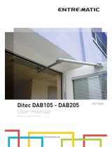
9. User instructions 12
9.1 General safety precautions
12
9.2 Manual release instruction
13
CAPTION
i
This symbol indicates instructions or notes regarding safety issues which require particular attention.
This symbol indicates informations which are useful for correct product function.

3
IP1812EN • 2012-07-10
1. GENERAL SAFETY PRECAUTIONS
This installation manual is intended for professionally competent personnel only.
Installation, electrical connections and adjustments must be performed in accordance with Good Working
Methods and in compliance with applicable regulations.
Before installing the product, carefully read the instructions.
Bad installation could be hazardous.
The packaging materials (plastic, polystyrene, etc.) should not be discarded in the environment or left within
reach of children, as these are a potential source of hazard.
Before installing the product, make sure it is in perfect condition.
Do not install the product in an explosive environment and atmosphere: gas or inammable fumes are a serious
hazard risk.
Before installing the motors, make all structural changes relating to safety clearances and protection or segre-
gation of all areas where there is risk of being crushed, cut or dragged, and danger areas in general.
Make sure the existing structure is up to standard in terms of strength and stability.
The motor manufacturer is not responsible for failure to use Good Working Methods in building the frames to
be motorized or for any deformation occurring during use.
The safety devices (photocells, safety edges, emergency stops, etc.) must be installed taking into account:
applicable laws and directives, Good Working Methods, installation premises, system operating logic and the
forces developed by the motorized gate.
The safety devices must protect any areas where the risk exists of being crushed, cut or gragged, or where
there are any other risks generated by the motorized gate.
Apply hazard area notices required by applicable regulations.
Each installation must clearly show the identication details of the motorized gate.
Before making power connections, make sure the plate details correspond to those of the power mains.
Fit an omnipolar disconnection switch with a contact opening gap of at least 3 mm.
Make sure an adequate residual current circuit breaker and overcurrent cutout are tted upstream of the elec-
trical system.
When necessary, connect the motorized gate to a reliable earth system made in accordance with applicable
safety regulations.
During installation, maintenance and repair, interrupt the power supply before opening the lid to access the
electrical parts.
To handle electronic parts, wear earthed antistatic conductive bracelets.
The motor manufacturer declines all responsibility in the event of component parts being tted that are
not compatible with the safe an correct operation.
For repairs or replacements of products only original spare parts must be used.
The installer shall provide all information relating to automatic, manual and emergency operation of the moto-
rized gate, and provide the user with operating instructions.

4
IP1812EN • 2012-07-10
2. DECLARATION OF INCORPORATION OF PARTLY COMPLETED MACHINERY
(Directive 2006/42/EC, Annex II-B)
The manufacturer DITEC S.p.A. with headquarters in Via Mons. Ban, 3 - 21042 Caronno Pertusella (VA) -
ITALY declares that the automation system for CUBIC swing gates:
- has been constructed to be installed on a manual door to construct a machine pursuant to the Directive
2006/42/EC. The manufacturer of the motorized door shall declare conformity pursuant to the Directive
2006/42/EC (annex II-A), prior to the machine being put into service;
- conforms to applicable essential safety requirements indicated in annex I, chapter 1 of the Directive
2006/42/EC;
- conforms to the Low Voltage Directive 2006/95/EC;
- conforms to the Electromagnetic Compatibility Directive 2004/108/EC;
- technical documentation conforms to Annex VII-B to the Directive 2006/42/EC;
- technical documentation is managed by Renato Calza with ofces in Via Mons. Ban, 3 - 21042 Caronno
Pertusella (VA) - ITALY;
- a copy of technical documentation will be provided to national competent authorities, following a suitably
justied request.
Caronno Pertusella, Silvano Angaroni
29-12-2009
(Managing Director)
2.1 Machinery Directive
Pursuant to Machinery Directive (2006/42/EC) the installer who motorizes a door or gate has the same obliga-
tions as the manufacturer of machinery and as such must:
- prepare the technical le which must contain the documents indicated in Annex V of the Machinery Directive;
(The technical le must be kept and placed at the disposal of competent national authorities for at least
ten years from the date of manufacture of the motorized door);
- draw up the EC Declaration of Conformity in accordance with Annex II-A of the Machinery Directive and
deliver it to the customer;
- afx the EC marking on the motorized door in accordance with point 1.7.3 of Annex I of the Machinery
Directive.

5
IP1812EN • 2012-07-10
3. TECHNICAL DATA
CUBIC6 CUBI6H CUBIC6HV
Power supply 230 V~ 50 Hz 24 V
24 V
Absorption 1,5 A 12 A 12 A
Couple 340 Nm 340 Nm 220 Nm
Capacitor 10 µF - -
Opening time 18 s/90° 12÷25 s/90° 6÷13 s/90°
Max opening 110°-180° (see page 7) 110°-180° (see page 7) 110°-180° (see page 7)
Service class 3 - FREQUENT 4 - INTENSIVE 4 - INTENSIVE
Intermittence
S2 = 15 min
S3 = 25%
S2 = 30 min
S3 = 50%
S2 = 30 min
S3 = 50%
Temperature
min -20° C max +55° C
min -35° C max +55° C
(with NIO enabled)
min -20° C max +55° C
min -35° C max +55° C
(with NIO enabled)
min -20° C max +55° C
min -35° C max +55° C
with NIO enabled
Degree of
protection
IP67 IP67 IP67
Control panel E2 - LOGICM VIVAH VIVAH
Applications
m = leaf width
kg = leaf weight
600 kg
500 kg
400 kg
300 kg
200 kg
100 kg
m 1 2 3 4 5
600 kg
700 kg
800 kg
500 kg
400 kg
300 kg
200 kg
100 kg
m12345
600 kg
500 kg
400 kg
300 kg
200 kg
100 kg
m12345
3.1 Operating instructions
Service class: 3 (minimum 30 cycles a day for 10 years or 60 cycles a day for 5 years).
Use: FREQUENT (For vehicle or pedestrian accesses to town houses or small condominiums with frequent use).
Service class: 4 (minimum 100 cycles a day for 10 years or 200 cycles a day for 5 years)
Use: INTENSIVE (For vehicle or pedestrian accesses to large condominiums, industrial or commercial complexes
and parking lots with very frequent use).
- Performance characteristics are to be understood as referring to the recommended weight (approx. 2/3 of
maximum permissible weight). When used with the maximum permissible weight a reduction in the above
mentioned performance can be expected.
- Service class, running times, and the number of consecutive cycles are to be taken as merely indicative
Having been statistically determined under average operating conditions, and are therefore not necessarily
applicable to speci c conditions of use.
- Each automatic entrance has variable elements such as: friction, balancing and environmental factors,
all of which may substantially alter the performance characteristics of the automatic entrance or curtail
its working life or parts thereof (including the automatic devices themselves). The installer should adopt
suitable safety conditions for each particular installation.
CUBIC6L*
CUBIC6LG**
CUBIC6TIG
CUBIC6TC
[CUBIC6C*] [CUBIC6CG**]

6
IP1812EN • 2012-07-10
4. STANDARD INSTALLATION
Ref. Code Description
1 GOL4 Transmitter
2 LAMPH
LAMP
Flashing light 24 V=
Flashing light 230 V~
3 XEL5
GOL4M
Key selector
Codied via radio control keyboard
4 LAB9 Magnetic loop detection device for trafc monitoring
5 E2
LOGICM
VIVAH
Control panel
6
CUBIC6
CUBIC6H
CUBIC6C
CUBIC6CG
CUBIC6CY
CUBIC6L
CUBIC6LG
CUBIC6TC
CUBIC6TIG
CUBIC6SBL
CUBIC6SBD
CUBIC6FM
CUBIC6FMTI
Geared motor 230 V~
Geared motor 24 V=
Foundation casing
Oversize foundation casing
Stainless steel foundation casing
Lever mechanism kit
Oversize lever mechanism kit
Chain-operated lever mechanism kit
Oversize gear-operated lever mechanism kit
Lever-operated release kit
Key-operated release kit
Magnetic limit switch kit
Magnetic limit switch kit for lever mechanism
7 XEL2
LAB4
Photocells
Photocells IP55
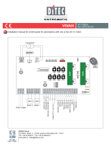
A Connect the power supply to an approved omnipolar switch with an opening distance
of the contacts of at least 3mm (not supplied).
The connection to the mains must be made via an independent channel, separated
from the connections to command and safety devices.
i
NOTE: the given operating and performance features can only be guaranteed with the use of DITEC
accessories and safety devices.
TX - 4x0.5 mm²
TX - 4x0.5 mm²
RX - 4x0.5 mm²
RX - 4x0.5 mm²
4x0.5 mm²
*
* 3x0,75 mm² + 1x1,5 mm² [CUBIC6]
2x1,5 mm² [CUBIC6H]
*
3x1.5 mm²
1
7
7
3
2
5
6
2x1.5 mm²
7
7
6
4
A

7
IP1812EN • 2012-07-10
5. Examples applications
max 110°
max 180°
max 180°
CUBIC6L - CUBIC6LG
CUBIC6TC
CUBIC6TIG

8
IP1812EN • 2012-07-10
6. INSTALLATION
Unless otherwise specied, all measurements are expressed in millimetres (mm).
6.1 Preliminary checks
Check that the structure is sufciently sturdy and that the hinge pivots are properly lubricated. Provide an
opening and closing stop.
Note: if the gate wing is more than 2.5 m wide, an electric lock should be installed.
6.2 Foundation case installation
Install the foundation case as indicated in the relevant manual.
6.3 Lever mechanisms installation
Choose and install the lever mechanisms as indicated in the relevant manual.
6.4 Wing release installation
Choose and install the door release mechanisms as indicated in the relevant manual.
WARNING: to install the releases more easily, we advise you to position the gate at the centre of the foundation
casing and remove the lid, in such a way as to have enough space for xing the screws.
6.5 Geared motor installation
After installing the foundation casing, the respective lever and release mechanisms go before the installation
of the gear motor as shown in the gure. NOTE: the gure shows the motor installed on the right door wing.
Carefully clean the bottom of the foundation casing from dirt or cement to guarantee an even laying of the
gearmotor.

9
IP1812EN • 2012-07-10
6.6 Installation with CUBIC6L-CUBIC6LG
Insert lever [A] on the gearmotor and position the mechanical stop [B] and [C] and adjust it, as shown in the gure.
NOTE: the gure shows the motor installed on the right door wing.
B
C
A
6.7 Installation with CUBIC6TC
Insert pinion [A] and join the two pinions by means of the chain [B], as shown in the gure.
Lubricate the chain and the lever mechanism as indicated in the gure.
B
A
WARNING: fasten the motor to the foundation case after connecting the chain.

10
IP1812EN • 2012-07-10
6.8 Installation with CUBIC6TIG
Fix the plate [A], then insert, x and lubricate the gears [B], [C] and [D]. Position the sphere [E] as shown in
the gure.
A
E
C
D
B
6.9 CUBIC6FM-CUBIC6FMTI installation
It is possible to limit the travel of the wing by means of magnetic limit switches.
Choose and install the magnetic limit switches as indicated in the relative manual.
Make the electrical connections as shown in the control panel.
WARNING: the magnetic limit switches cannot interrupt the power supply to the motor.

11
IP1812EN • 2012-07-10
7. ELECTRICAL CONNECTIONS
Before connecting the power supply, make sure the plate data correspond to that of the mains power supply.
An omnipolar disconnection switch with minimum contact gaps of 3 mm must be included in the mains supply.
Check that upstream of the electrical installation there is an adequate residual current circuit breaker and a
suitable overcurrent cutout.
WARNING: the electrical connections for the extension of the motor cables must be made on the outside of the
foundation casing in an appropriate junction box (not supplied).
In the CUBIC6 gearmotors, the blue wire corresponds to the common contact of the motor phases, and must
be connected to the W or Z terminals of the control panel.
The CUBIC6 gearmotor can be connected to the E2 and LOGICM control panels.
The CUBIC6H and CUBIC6VH gearmotors can be connected to the VIVAH control panel.
The electrical connections and the start-up of the gearmotors are shown in the installation manuals of the E2,
LOGICM and VIVAH control panels.
8. ROUTINE MAINTENANCE PLAN
Perform the following operations and checks every 6 months according to intensity of use of the automation.
Without 230 V~ power supply and batteries if present:
- Lubricate the levers of the gearmotor.
- Lubricate the rotation pivot of the gate leaf.
- Lubricate the gate leaf hinges.
- Check the good conditions of the electric connection.
- Check that the xing screws of the gearmotor are rmly tightened.
- Clean the inside of the cases and check that drain is not clogged.
- Check the value of the capacity of the motor condenser.
Reconnect the 230 V~ power supply and batteries if present:
- Check the power adjustment.
- Check the good operation of all command and safety functions (photocells).
- Check the good operation of the release system.
NOTE: For spare parts, see the spares price list.
i

12
IP1812EN • 2012-07-10

13
IP1812EN • 2012-07-10
DETACH AND DELIVER TO THE CUSTOMER
9.1 General safety precautions
The following precautions are an integral and essential part of the product and must be supplied to the user.
Read them carefully since they contain important information on safe installation, use and maintenance.
These instructions must be kept and forwarded to all possible future users of the system.
This product must only be used for the specic purpose for which it was designed.
Any other use is to be considered improper and therefore dangerous.
The manufacturer cannot be held responsible for any damage caused by improper, incorrect or unreasonable use.
Avoid operating in the proximity of the hinges or moving mechanical parts.
Do not enter within the operating range of the motorized door while it is moving.
Do not block the movement of the motorized door since this may be dangerous.
Do not allow children to play or stay within the operating range of the motorized door.
Keep remote controls and/or any other control devices out of the reach of children in order to avoid possible
involuntary activation of the motorized door.
In the event of fault or malfunctioning of the product, turn off the power supply switch, do not attempt to repair
or intervene directly and contact only professionally competent personnel.
Failure to comply with the above may cause a dangerous situation.
All cleaning, maintenance or repair work must be carried out by professionally competent personnel.
To ensure that the system works efciently and correctly, the manufacturer’s indications must be complied with
and routine maintenance of the motorized door must be performed by professionally competent personnel.
In particular, regular checks are recommended in order to verify that the safety devices are operating correctly.
All installation, maintenance and repair work must be documented and made available to the user.
For the correct disposal of electric and electronic equipment, waste batteries and accumulators, the user
must take such products to the designated municipal collection facilities.
CUBIC6
9. Operating instructions

14
IP1812EN • 2012-07-10
DETACH AND DELIVER TO THE CUSTOMER
In the event of failure or if there is no voltage:
CUBIC6SBL: insert the lock release lever and rotate by 180° (g.1). Release any electric lock. Manually open
the gate.
CUBIC6SBD: insert the lock release key in the lock and rotate by 180° (g.2). Release any electric lock. Ma-
nually open the gate.
To block the door wings again: rotate the lock release lever or key by 180°. Move the door wing manually until
it is completely reattached.
WARNING: the door wing block and release operations must be performed with the motor idle.
9.2 Manual release instructions
Fig. 1 Fig. 2
Installer:
DITEC S.p.A.
Via Mons. Ban, 3
21042 Caronno Pertusella (VA) - ITALY
Tel. +39 02 963911 - Fax +39 02 9650314
www.ditec.it - [email protected]
TM

15
IP1812EN • 2012-07-10

TM
DITEC S.p.A. Via Mons. Ban, 3 21042 Caronno P.lla (VA) Italy Tel. +39 02 963911 Fax +39 02 9650314
www.ditec.it [email protected]
DITEC BELGIUM LOKEREN Tel. +32 9 3560051 Fax +32 9 3560052 www.ditecbelgium.be DITEC DEUTSCHLAND OBERURSEL
Tel. +49 6171 914150 Fax +49 6171 9141555 www.ditec-germany.de DITEC ESPAÑA ARENYS DE MAR Tel. +34 937958399
Fax +34 937959026 www.ditecespana.com DITEC FRANCE MASSY Tel. +33 1 64532860 Fax +33 1 64532861 www.ditecfrance.com
DITEC GOLD PORTA ERMESINDE-PORTUGAL Tel. +351 22 9773520 Fax +351 22 9773528/38 www.goldporta.com DITEC SWITZERLAND
BALERNA Tel. +41 848 558855 Fax +41 91 6466127 www.ditecswiss.ch DITEC ENTREMATIC NORDIC LANDSKRONA-SWEDEN
Tel. +46 418 514 50 Fax +46 418 511 63 www.ditecentrematicnordic.com DITEC TURCHIA ISTANBUL Tel. +90 21 28757850
Fax +90 21 28757798 www.ditec.com.tr DITEC AMERICA ORLANDO-FLORIDA-USA Tel. +1 407 8880699 Fax +1 407 8882237
www.ditecamerica.com DITEC CHINA SHANGHAI Tel. +86 21 62363861/2 Fax +86 21 62363863 www.ditec.cn
/