Simplicity 1695411 Owner's manual
- Category
- Snow throwers
- Type
- Owner's manual

Bimpliuitq
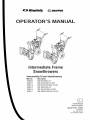
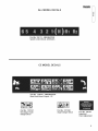
0 P E RATO UAL
Jn rrne ia Frame
Snowthrowers
intermediate Frame Snowthrowers
IVlfg. No.
1695302
1695311
1695410
1695313
1695314
1695411
Description
SM11924E B&S 24
SM11924EX B&S 24 (CE)
SM11924RX MS B&S 24 (CE)
SNP 1924EB&S 24
SNP 11924EXB&S 24 (CE)
SNP 1924RXMS B&S 24 (CE)
CAUTION:Readand
followallinstructions.
ManualPartNo.1734501
Revision 01
Rev.Date08/2007
TP 100-4609-01-1W-SN

SAVETHESEiNSTRUCTiONS
READTHEMANUAL
Theoperator'smanualcontainsimportantsafetyinformationyouneedtobeawareofBEFOREyouoperateyourunitas
wellasDURINGoperation.
Safe operating techniques, an explanation of the product's features and controls, and maintenance
information is included to help you get the most out of your equipment investment,
Failure to obey the safety rules could result in loss of control of the unit, severe personal injury or death to
you, or bystanders, or damage to property or equipment,
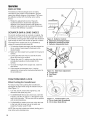
Safety icons
Thealert symbol,i_ is usedto identify safety information
about hazardsthat can result inpersonal injury. A signal
word (DANGER,WARNING,or CAUTION)is usedwith the
alert symbol to indicatethe likelihood and the potential
severity of the injury. In addition, a hazardicon may be used
to representthe type of hazard. An explanationof hazard
levels and icons are asfollows:
DANGER
This indicates a hazardwhich, if not avoided, will resultin
seriousinjuryor death.
WARNING
This indicates a hazardwhich, if not avoided, couldresult in
seriousinjuryor death.
CAUTION
This indicates a hazardwhich, if not avoided, might result in
minor or moderate injury.
WARNING
You must read, understand and comply with all
safety and operating instructions in this
manual before attempting to set-up and
operate your snowthrower.
Failure to comply with all safety and operating
instructions can result in loss of machine
control, serious personal injury to you and/or
bystanders, and risk of equipment and
property damage. The triangle in the text
signifies important cautions or warnings which
must be followed.
WARNING
Engine exhaust from this product contains
chemicals known, in certain quantities, to
cause cancer, birth defects, or other
reproductive harm.
SAFETY DECALS
This unit has been designed and manufactured to
provide you with the safety and reliability you would
expect from an industry leader in outdoor power
equipment manufacturing.
Although reading this manual and the safety
instructions it contains will provide you with the
necessary basic knowledge to operate this equipment
safely and effectively, we have placed several safety
labels on the unit to remind you of this important
information while you are operating your unit.
All DANGER, WARNING, CAUTION and
instructional messages on your product should be
carefully read and obeyed, Personal bodily injury can
result when these instructions are not followed, The
information is for your safety and it is important,
If any decals are lost or damaged, replace them at
once. See your local dealer for replacements.
These labels are easily applied and will act as a
constant visual reminder to you, and others who may
use the equipment, to follow the safety instructions
necessary for safe, effective operation.
Read and obey a// operation and warning decals.

Table of Contents
Operator Safety .......................................... 2
Readthe Manual ............................................. 2
SafetyRules and information.................................... 4
SafetyDecals................................................ 8
Safetyicons ................................................ 10
identification Numbers........................................ 11
Features & Controls ...................................... 12
Control Locations............................................ 12
Operation ............................................. 14
GeneralOperation ........................................... 14
Starting Controls ............................................ 15
Starting the Engine........................................... 16
Stopping the Engine.......................................... 17
Operatingthe Snowthrower.................................... 17
Ground SpeedSelector ....................................... 17
EngineSpeed............................................... 17
Deflector .................................................. 18
Scraper Bar& Skid Shoes..................................... 18
Traction Drive Lock .......................................... 18
Clearinga CloggedDischargeChute ............................. 19
After EachUse.............................................. 19
Storage ................................................... 19
Maintenance ........................................... 20
MaintenanceSchedule........................................ 21
CheckingTire Pressure ....................................... 21
Auger GearCaseLubrication ................................... 21
Lubrication................................................. 21
RegularMaintenance......................................... 22
Troubleshooting, Adjustment, and Service ....................... 24
Troubleshooting............................................. 24
Adjustments ............................................ 26
Auger Drive Adjustment....................................... 26
Traction Drive CableAdjustment ................................ 26
Run-in Adjustment........................................... 27
BeltAdjustment ............................................. 28
Shear Pin Replacement....................................... 29
Belt GuideAdjustment ........................................ 29
Belt Replacement............................................ 30
Specifications .......................................... 35
Parts and Accessories ............................... BackCover
Parts .......................................................
Maintenanceitems.............................................
TechnicalManuals.............................................
Co
d)
"1"1
CP
r-
Cb
©
©
60
O
-C_
d)
©
d_
O
d)
f---.,
-q
©
C
CT
©
©
¢O
r-
B
d)
Co
d_
<
O
d)
Co
-O
d)
_o
O
m.
©
3

ill
O9
g
Congratulations on purchasing a superior-quality piece of
lawn and garden equipment. Our products are designed
and manufactured to meet or exceed all industry
standards for safety.
Power equipment is only as safe as the operator. If it is
misused, or not properly maintained, it can be dangerous!
Remember, you are responsible for your safety and that of
those around you.
Use common sense, and think through what you are
doing. If you are not sure that the task you are about to
perform can be safely done with the equipment you have
chosen, ask a professional: contact your local authorized
dealer.
The operator's manual contains important safety
information you need to be aware of BEFORE you operate
your unit as well as DURING operation.
Safe operating techniques, an explanation of the product's
features and controls, and maintenance information is
included to help you get the most out of your equipment
investment.
Be sure to completely read the Safety Rules and
Information found on the following pages. Also completely
read the Operation section.
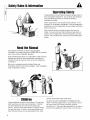
DII
Tragic accidents can occur with children. Do not allow
them anywhere near the area of operation. Children
are often attracted to the unit and snowthrowing
activity. Never assume that children will remain where
you last saw them. If there is a risk that children may
enter the area where you are operating the unit, have
another responsible adult watch them.
DO NOT ALLOW CHILDREN TO OPERATE THIS
UNIT! This encourages them to come near the unit in
the future while it is running, and they could be
seriously hurt. They may then approach the unit when
you are not expecting it, and you may run over them.
4

SaletyRulesandInfomatm
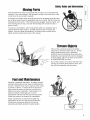
N0vJng
This equipment has many moving parts that can injure you or someone else.
However, ifyou are standing in the operator's position, and follow all the rubs
in this book, the unit issafe to operate.
The auger and impeller have spinning parts that can amputate hands and feet.
Do not allow anyone near the equipment while it is running! DO NOT clear the
discharge chute by hand. If the chute becomes plugged, stop the engine, wait
for all moving parts to stop, and clear the blockage with a clean-out tool or
piece of wood.
To help you, the operator, use this equipment safely, it is equipped with an
operator-present safety system. Do NOT attempt to alter or bypass the
system. See your dealer immediately if the system does not pass all the
safety interlock system tests found in this manual.
Co
,--t-
Thrown ects
This unit has a spinning auger and impeller.
They pick up and throw snow and ice. Thrown
debris could seriously injure a bystander.
ALWAYS direct the discharge chute away from
bystanders and property that could be damaged
by frying debris. Be sure to clean up the area to
be cleared BEFORE you start.
Do not allow anyone in the area while the unit is
running! If someone does enter the area, shut
the unit off immediately until they leave.
Gasoline is extremely flammable. Its vapors are also
extremely flammable and can travel to distant ignition
sources. Gasoline must only be used as a fuel, not as
a solvent or cleaner. It should never be stored any
place where its vapors can build up or travel to an
ignition source like a pilot light. Fuel belongs in an
approved, plastic, sealed gas can, or in the
snowthrower fuel tank with the cap securely closed.
Spilled fuel needs to be cleaned up immediately.
Proper maintenance is critical to the safety and
performance of your unit. Be sure to perform the
maintenance procedures listed in this manual,
especially periodically testing the safety system.
5

SafetyRules& Informtm
_j
This machine is capable to amputating hands and feet and throwing objects. Read these safety rules
and follow them closely. Failure to obey these rules could result in loss of control of unit, severe
personal injury or death to you, or bystanders, or damage to property or equipment. _The triangle in
text signifies important cautions or warnings which must be followed.
TRAINING
1. Read, understand, and follow all instructions on the
machine and in the manuals before operating this
unit. Be thoroughly familiar with the controls and
the proper use of the equipment. Know how to
stop the unit and disengage the controls quickly.
2. Never allow children to operate the equipment.
Never allow adults to operate the equipment
without proper instruction.
3. Keep the area of operation clear of all persons,
particularly small children and pets.
4. Exercise caution to avoid slipping or falling
especially when operating in reverse.
PREPARATION
1. Thoroughly inspect the area where the equipment
is to be used and remove all doormat, sleds,
boards, wires, and other foreign objects.
2. Disengage all clutches and shift into neutral before
starting engine (motor).
3. Do not operate the equipment without wearing
adequate winter outer garments. Wear footwear
that will improve footing on slippery surfaces.
Avoid loose fitting clothing that can get caught in
moving parts.
4. Handle fuel with care; it is highly flammable.
(a) Use an approved fuel container.
(b) Never add fuel to a running engine or hot
engine.
(c) Fill fuel tank outdoors with extreme care. Never
fill fuel tank indoors. Replace fuel cap securely
and wipe up spilled fuel.
(d) Never fill containers inside a vehicle or on a
truck or trailer bed with a plastic liner. Always
place containers on the ground, away from your
vehicle, before filling.
(e) When practical, remove gas-powered
equipment from the truck or trailer and refuel it on
the ground. If this is not possible, then refuel such
on a trailer with a portable container, rather than
from a gasoline dispenser nozzle.
(f) Keep nozzle in contact with the rim of the fuel
tank or container opening at all times, until
refueling is complete. Do not use a nozzle lock-
open device.
(g) Replace gasoline cap securely and wipe up
spilled fuel.
(h) If fuel is spilled on clothing, change clothing
immediately.
5. Use extension cords and receptacles as specified
by the manufacturer for all units with electric drive
motors or electric starting motors.
6. Adjust the collector housing height to clear gravel
or crushed rock surfaces.
7. Never attempt to make any adjustments while the
engine (motor)is running (except when specifically
recommended by the manufacturer).
8. Let engine (motor) and machine adjust to outdoor
temperatures before starting to clear snow.
9. Always wear safety glasses or eye shields during
operation or while performing an adjustment or
repair to protect eye from foreign objects that may
be thrown from the machine.
OPERATION
1. Do not put hands or feet near or under rotating
parts. Keep clear of the discharge opening at all
times.
2. Exercise extreme caution when operating on or
crossing gravel drives, walks, or roads. Stay alert
for hidden hazards or traffic.
3. After striking a foreign object, stop the engine
(motor), remove the wire from the spark plug,
disconnect the cord on electric motors, thoroughly
inspect the snowthrower for any damage, and
repair the damage before restarting and operating
the snowthrower.
4. If the unit should start to vibrate abnormally, stop
the engine (motor) and check immediately for the
cause. Vibration is generally a warning of trouble.
5. Stop the engine (motor) whenever you leave the
operating position, before unclogging the
collector/impeller housing or discharge guide, and
when making any repairs, adjustments, or
inspections.
6. When cleaning, repairing, or inspecting make
certain the collector/impeller and all moving parts
have stopped. Disconnect the spark plug wire and
keep the wire away from the plug to prevent
accidental starting.
7. Do not run the engine indoors except for starting
the engine or for transporting the snowthrower in or
out of the building. Open the outside doors;
exhaust fumes are dangerous.
8. Exercise extreme caution when operating on
slopes. Do not attempt to clear steep slopes.
9. Never operate the snowthrower without proper
guards plates, or other safety protective devices in
place and working.
10. Never direct the discharge toward people or areas
where property damage can occur. Keep children
and others away.
11. Do not overload the machine capacity by
attempting to clear snow at too fast a rate.
12. Never operate the machine at high transport
speeds on slippery surfaces. Look behind and use
care when operating in reverse.
13. Disengage power to the collector/impeller when
snowthrower is transported or not in use.
14. Use only attachments and accessories approved
by the manufacturer of the snowthrower (such as
wheel weights, counterweights, or cabs).
15. Never operate the snowthrower without good
visibility or light. Always be sure of your footing,
and keep a firm hold on the handles. Walk, never
run.
16. Never touch a hot engine or muffler.
17. Never operate the snowthrower near glass
enclosures, automobiles, window wells, drop-offs,
and the like without proper adjustment of the
6

discharge angle.
18. Never direct discharge at bystanders or allow
anyone in front of the unit.
19. Never leave a running unit unattended. Always
disengage the auger and traction controls, stop
engine, and remove keys.
20. Do not operate the unit while under the influence of
alcohol or drugs.
21. Keep in mind the operator is responsible for
accidents occurring to other people or property.
22. Data indicates that operators, age 60 years and
above, are involved in a large percentage of power
equipment-related injuries. These operators
should evaluate their ability to operate the unit
safely enough to protect themselves and others
from injury.
23. DO NOT wear long scarves or loose clothing that
could become entangled in moving parts.
24. Snow can hide obstacles. Make sure to remove all
obstacles from the area to be cleared.
CHILDREN
Tragic accidents can occur if the operator is not alert to
the presence of children. Children are often attracted to
the unit and the operating activity. Never assume that
children will remain where you last saw them.
1. Keep children out of the area and under the
watchful care of another responsible adult.
2. Be alert and turn unit off if children enter the area.
3. Never allow children to operate the unit.
4. Use extra care when approaching blind corners,
shrubs, trees, or other objects that may obscure
vision.
CLEARING A CLOGGED DISCHARGE
CHUTE
Hand contact with the rotating impeller inside the
discharge chute is the most common cause of injury
associated with snowthrowers. Never use your hand
to clean out the discharge chute.
To clear the chute:
1. SHUT OFF THE ENGINE.
2. Wait 10 seconds to be sure the impeller blades
have stopped rotating.
3. Always use a clean out tool, not your hands.
SERVICE, MAINTENANCE, AND STORAGE
1. Check shear bolts and other bolts at frequent
intervals for proper tightness to be sure the
equipment is in safe working condition.
2. Never store the machine with fuel in the fuel tank
inside a building where ignition sources are present
such as hot water and spacer heaters, or clothes
dryers. Allow the engine to cool before storing in
any enclosure.
3. Always refer to the operator's manual for important
details if the snowthrower is to be stored for an
extended period.
4. Maintain or replace safety and instruction labels as
necessary.
5. Run the machine a few minutes after throwing
snow to prevent freeze-up of the collector/impeller.
6. If fuel is spilled, do not attempt to start the engine
but move the machine away from the area of
spillage and avoid creating any source of ignition
SafetyRulesaridIflfematm
until fuel vapors have dissipated.
7. Always observe safe refueling and fuel handling
practices when refueling the unit after
transportation or storage.
8.Always follow the engine manual instructions for
storage preparations before storing the unit for
both short and long term periods.
9. Always follow the engine manual instructions for
proper start-up procedures when returning the unit
to service.
10. Maintain or replace safety and instruction labels as
necessary.
11. Keep nuts and bolts tight and keep equipment in
good condition.
12. Never tamper with safety devices. Check their
proper operation regularly and make necessary
repairs if they are not functioning properly.
13.Components are subject to wear, damage, and
deterioration. Frequently check components and
replace with manufacturer's recommended parts,
when necessary.
14.Check control operation frequently. Adjust and
service as required.
15. Use only factory authorized replacement parts
when making repairs.
16.Always comply with factory specifications on all
settings and adjustments.
17.Only authorized service locations should be utilized
for major service and repair requirements.
18. Never attempt to make major repairs on this unit
unless you have been properly trained. Improper
service procedures can result in hazardous
operation, equipment damage and voiding of
manufacturer's warranty.
19.Check shear bolts and other bolts at frequent
intervals for proper tightness to be sure the
equipment is in safe working condition.
EMISSIONS
1. Engine exhaust from this product contains
chemicals known, in certain quantities, to cause
cancer, birth defects, or other reproductive harm.
2. If available, look for the relevant Emissions
Durability Period and Air Index information on the
engine emissions label.
IGNITION SYSTEM
1. This spark ignition system complies with Canadian
ICES-002.
Co
,--.4-
7

>,
O9
_j
DECALS
This unit has been designed and manufactured to
provide you with the safety and reliability you would
expect from an industry leader in outdoor power
equipment.
Although reading this manual and safety instructions it
contains will provide you with the necessary basic
knowledge to operate this equipment safely and
effectively, we have placed several safety labels on
the unit to remind you of this important information
while you are operating your unit.
All WARNING, CAUTION, and instructional messages
on your unit should be carefully read and obeyed.
Personal bodily injury can result when these
instructions are not followed. The information is for
your safety and it is important.
The safety decals below are on your unit.
If any of these decals are lost or damaged, replace
them at once. See your local dealer for replacements.
These labels are easily applied and will act as a
constant visual reminder to you, and others who may
use the equipment, to follow the safety instructions
necessary for safe, effective, operation.
NOTE. Engine operation and safety decals are
supplied by the engine manufacturer.
NORTH AMERICAN MODEL DECALS
Carbonmonoxide hazard
Thisengineemitspoisonouscarbonmonoxidegas
-Avoidhlha_ingexhaustfumes
-0n_yoperateou_doms
_ Fire hazard
# Gasolineisflm_/mablo.
-klbw engineto coo_for at_east3 minu_esbefore
refuding
• Keeparea ofoperation clearof
all persons,especiallychildren.
• Keepmachine maintained • Neverallow children to
and guards inplace, operatethesnow';hrower.
• Stopengine anddisconnect • Always direct dischargechuteso
spark plug wire before as toavoid iniury to personsor
servicing the unit• damagetoproperty.
Part No. 1734499 - DASH SMI/SNAPPER
Main Dash Decal, North American
,_ • The lubrication poir0s s]mW4Hlere mtlSt be lubricated .__xb ,t_"
w4th_0weightoil_,_r_'101,oursofope_t_on,and
• be_o,_u,ingthe..,itaf_,S_o,age,_aiiLi,_toiub,i_at_
Part No. 1733526
Lubrication Decal
_j Amputation hazard
I'_ pKeephandsfeetandd0thing I
]...........................!:!:_!!:1!'1:!_!_!::_:':
DGCBIS
ALL MODEL DECALS
Part No. 724172 - SMI/SNAPPER
Speed Control Decal, All Models
Co
,<
CE MODEL DECALS
Part No. 1734591 - SMI/SNAPPER
Main Dash Decal, Export - CE
Part No. 1727207
Discharge Chute
Danger Decal
Part No. 1727208
Auger Danger Decal
Part No. 728183
important
Over Adjustment
9

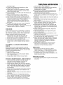
SAFETY iCONS
WARNING: READ OPERATOR'S
MANUAL.
Read and understand the
Operator's Manual before using this
machine.
DANGER: THROWN OBJECTS.
This machine is capable of throwing
objects and debris, Keep
bystanders away,
WARNING: REMOVE KEY BEFORE
SERVICING.
Remove the key, disconnect spark
plug wire, and consult technical
literature before performing repairs
or maintenance,
iiiiiili_i_!i!;_........._ii!i!i!i!iii_i!ii!i!ii_!!iiii!!i!!iiiiii
WARNING: DISMEMBERMENT.
This machine can amputate limbs.
Keep bystanders and children away
when engine is running.
DANGER:D|SMEMBERMENT.
The auger can amputate limbs.
Keep hands and feet away from
auger and rotating parts.
DANGER:DISMEMBERMENT.
The impeller can amputate limbs.
Stop the engine, remove the key,
and disconnect spark plug wire
before clearing the discharge chute
or performing service work. Keep
hands and feet away from impeller
and rotating parts.
10

""='_ _[_piicity Manufacturing, inc.
=\_ W_"_ington WJ 53074-0997 USA
Illllllllllllllllllll_4i_._lllllllllH
!!!!!!!!!!!!!!!!!!!!!!!;x?
North American /
CE Models
CE Models
(Only)
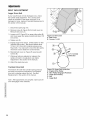
When contacting your authorized dealer for
replacement parts, service, or information you
MUST have these numbers.
Record your model name/number, manufacturer's
identification numbers, and engine serial numbers in
the space provided for easy access. These numbers
can be found in the locations shown.
NOTE: For location of engine identification numbers,
refer to the engine owner's manual.
CE Models: Place the extra copy of the identification
tag in the manual
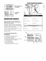
CE IDENTIFICATION TAG
MARKINGS
A. Manufacturer's Identification Number
B. Manufacturer's Serial Number
C. Power Rating in Kilowatts
D. Maximum Engine Speed in Rotations per Minute
E. Manufacturer's Name and Address
F. Year of Manufacture
G. CE Compliance Logo
H. Mass of Unit in Kilograms
I. Guaranteed Sound Power in Decibels
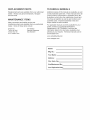
ProductIdentificationNumbers
Serial Sticker
Model Description Name/Number
Unit MFGNumber Unit SERIAL Number
Mower Deck MFG Number Mower Deck SERIAL Number
Dealer Name Date Purchased
¢,
'Part No. xxxxxxx
IIIIIIIIIIIIIIIIIIIIIIIIIII
XXXXXXXXXXXXXXX
Serial No. xxxxxxxxxx
IllllllHIIIIIIIIHHIIIIIIII
XXXXXXXXXXXXXXXXXXXXXXX
:::::::::::::::::::::::(g
xxxxxxxxxxxxxxxxxxxxx(_ 20%
CO
,'-4-
'<
11

¢o
©
,+_
c
©
L)
o5
¢o
dJ
(6
d)
LL
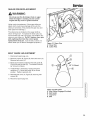
Festures
Please take a moment
and familiarize
yourseff with the
name, location, and
function of these
controls so that you will
better understand the
safety and operating
instructions provided in
this manual.
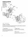
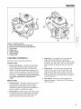
Figure 1. Control Locations
I',l
G'
CONTROL LOCATIONS
The information below briefly describes the function of individual controls. Starting, stopping, and driving require
the combined use of several controls applied in specific sequences. To learn what combination and sequence of
controls to use for various tasks see the OPERATION section.
1_2_,
Speed Selector
Selects forward speeds 1-6 and reverse speeds 1-2.
No neutral position or gate is required, since the
traction drive design automatically provides "neutral"
(no forward or reverse movement), whenever the
Drive Control is released.
_ Auger Control
Engages the auger/impeller when depressed.
Releasing the control stops the auger/impeller.
_ Drive Control
Engages the traction drive to wheels when depressed.
Releasing the control stops the traction drive.
12

_ Chute Direction Control
Rotating the knob to the left will turn the spout to the
left side and rotating the knob to the right will rotate
the spout to the right side.
L_ Chute Deflector Control
Chute Deflector Knob: Locks chute deflector in
desired position. Tilting the chute deflector UP
provides a higher stream and greater distance, while
tilting the deflector DOWN provides a lower stream
and less distance.
'0_0' Traction Locking Pins
Traction Lock Pins: The wheels can be completely
released using the locking pin (see Figure 11). This
allows the unit to be easily moved with the engine off.
| On/Stop Switch
Turn the the switch to the ON position to operate the
engine. Turn the switch to the OFF position to stop
the engine.
(_) Starter
Electric Start (Select Models): Depressing the
starter button activates the electric starter. The
electric start button operates on AC current, which is
provided by connection of the extension cord
provided. Connect this extension cord ONLY to a
properly grounded 3 prong electrical outlet.
Recoil Starter (All Models): Pulling the recoil handle
cranks the engine,
J_ Fuel
Fuel tank filler cap (see illustration). Note: The fuel
shut off valve is located under the fuel tank or on the
front of the engine, Close the valve when the
snowthrower is not in use. Open the valve before
starting.
I"-_- Primer Button
When pressed, the primer button provides initial fuel
to help start a cold engine. Normally, pressing the
primer button twice will provide enough fuel to start a
cold engine.
Features& Controls
Engine Key
The engine key prevents the engine from being
started. The key must be fully inserted into the key
slot for the unit to start. The key can also used to stop
the engine by pulling the key out of the key slot,
I"-I Choke Knob
The choke knob adjusts the air/fuel mixture, and is
used to help start a cold engine by providing a richer
mixture. Once the engine is warm and running
smoothly, the choke knob should be set to the off
position to provide a normal air/fuel mix.
t.-
CD
('b
©
O
13

c
©
.m
,+_
s=,.
(D
o
in
GENERAL OPERATION
CHECKS BEFORE EACH START-UP
1. Make sure all safety guards are in place and all
nuts, bolts and clips are secure.
2. Check to make sure that the clean-out is attached
to the auger housing. Do not operate the machine
without the clean-out tool properly stored on the
auger housing.
3. Check the engine oil level. See your engine
owner's manual for procedure and specifications.
4. Check to make sure spark plug wire is attached
and spark plug is tightened securely. If necessary,
torque spark plug to 15 ft. Ibs.
5. Check the fuel supply. Fill the tank no closer than
1/4 to 1/2 inch of top of tank to provide space for
expansion. See your engine owner's manual for
fuel recommendations.
.
.
.
Check the scraper bar to make sure it is set at the
desired height. Adjust the skid shoes if necessary.
Check the drive control (_,Figure 1), and
auger
(_,Figure 1) for proper operation.
control If
i
adjustment is required, see the service section for
procedures.
Check the chute direction control (_,J
,Figure 1)
for proper operation. The discharge chute should
rotate freely in both directions. See the service
section for adjustment procedures and
troubleshooting.
9. Check the chute deflector (_'_ Figure 1) for
proper operation. The deflector should pivot freely
up and down when knob is loosened.
10. Position the chute at the desired starting direction
and set the deflector at the desired angle.
11. Check the speed selector ( 1,2.,,Figure 1) for
smooth operation. The control must move freely
into each speed position gate and remain in
position when released. If the speed selector does
not move freely into all forward and reverse speed
positions, contact your local authorized dealer for
assistance.
WARNING
This unit is a "two-stage" snowthrower.
The first stage is the auger, which feeds the
snow back into the impeller housing. The
second stage is the impeller, which throws the
snow out the discharge chute. If bodily contact
is made with the auger or impeller when they
are rotating, severe personal injury will occur.
To avoid injury, keep others and yourself away
from the auger and the discharge chute
whenever the engine is running. Read and
follow all of the safety rules and warnings in
this manual.
,I DANGER
Do not clean out discharge chute with hands.
Contact with moving parts inside chute will
cause serious injury. Use clean out tool
provided with machine. Use the following
procedure to remove objects or clear the
chute:
1. Stop the engine. Remove the key
2. Wait 10 seconds to be sure the auger/impeller
blades have stopped rotating.
3. Always use the clean-out tool. DO NOT use your
hands.
WARNING
For your safety, operation on slopes should be
in an up and down direction only. If it becomes
necessary to move across the face of a slope,
use caution and do not blow snow. Be very
careful when changing direction on a slope.
Proper winter footwear is recommended for the
operator to help prevent slipping. Never
attempt to clean snow from excessively steep
slopes. The maximum slope for any operation
is 17.7% (10°).
WARNING
Gasoline is highly flammable and must be
handled with care. Never fill the tank when the
engine is hot or running. Always move
outdoors to fill the tank. Keep snowthrower
and gasoline away from open flame or spark.
14

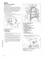
Operation
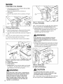
Figure 2. Engine Controls
A. Electric Start Button (Select Models)
B. Electric Start Connection (Select Models)
C. Stop Switch
D. Engine Key
E. Starter Handle
F. Primer Button
G. Choke Knob
STARTING CONTROLS
See Figure 2 for the following instructions.
Electric Start
Electric Start Button - The Electric Start Button
(A) activates an electric starter mounted to the
engine, eliminating the need to pull the starter
handle. The Electric Start Button operates on AC
current, which is provided by connection (B) to the
extension cord provided with units equipped with
this feature. Connect this extension cord ONLY
to a properly grounded 3 prong electrical
outlet.
Manual Start
2. Starter Handle - The starter handle (E) connects
to a starter cord to manually start the engine.
Pulling starter handle rapidly spins the engine
crankshaft, cycles the engine, and generates the
spark necessary for starting the engine.
3. Primer Button - When pressed, the primer button
(F) provides initial fuel to help start a cold engine.
Normally, pressing the primer button twice will
provide enough fuel to start a cold engine.
4_
5_
6_
Engine Key - The engine key (D) prevents the
engine from being started by unauthorized
individuals. The key must be fully inserted into the
key slot for the unit to start. The key is also used to
stop the engine by pulling the key out of the key
slot.
Choke Knob - The choke knob (G) adjusts the
air/fuel mixture, and is used to help start a cold
engine by providing a richer mixture. Once the
engine is warm and running smoothly, the choke
knob should be set to the off position to provide a
normal air/fuel mix.
Stop Switch - Switch (C) to the ON position to
operate the engine. Switch to the OFF position to
stop the engine.
O
,'-4-
O
15

OpepatJon
STARTING THE ENGINE
1. Check the oil level. See the Engine Manual How
to Check/Add Oil section
2. Make sure equipment drive controls are
disengaged.
3. Push the stop switch to the on position (A, Figure
3).
c
©
.m
,+_
_=.
o
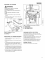
Figure 3. On/Stop Switch
A. On/Stop Switch Selector
4. Insert the engine key (A, Figure 4) into the engine
key slot and push fully in to the RUN position.
5. Turn the choke knob (B) fully clockwise if engine is
cold.
Note: Do not use the choke to start a warm engine.
6. Push the primer button (C) two times.
Note: Do not use the primer to start a warm engine.
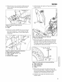
Figure 5. Rewind Start
A. Starter Cord Handle
Note: If the engine does not start after three attempts,
see the Engine Manual Troubleshooting section.
8. Electric Start: First connect the extension cord to
the power cord receptacle and then into a wall
receptacle. If additional extension cord is
required, make sure it is 3-wire.
WARNING
if the extension cord is damaged, it must be
replaced by the manufacturer or its service
agent or a similarly qualified person to avoid to
avoid a hazard.
,
Electric Start: Depress the push button (A, Figure
6). After you start the engine, first disconnect the
extension cord from the wall receptacle and then
from the power cord receptacle (B).
16
Figure 4. Safety Key, Choke, and Primer Button
A. Safety Key
B. Choke Control Knob
C. Primer Button
7. Rewind Start: Firmly hold the starter cord handle
(A, Figure 5). Pull the starter cord handle slowly
until resistance is felt, then pull rapidly.
, WARNING
Rapid retraction of the starter cord (kickback)
will pull your hand and arm toward the engine
faster than you can let go. Broken bones,
fractures, bruises or sprains could result.
When starting engine, pull the starter cord
slowly until resistance is felt and then pull
rapidly to avoid kickback.
Figure 6. Electric Start
A. Starter Push Button
B. Power Cord Receptacle
hLCAUTION
To extend the life of the starter, use short
starting cycles (five seconds maximum.) Wait
one minute between starting cycles.
Note: If the engine does not start after three attempts,
see the Engine Manual Troubleshooting section.

STOPPING THE ENGINE
, WARNING
Gasoline and its vapors are extremely
flammable and explosive.
Fire or explosion can cause severe burns or
death.
DO NOT choke the carborator to stop the
engine.
1. Move the stop switch (A, Figure 7) to the stop
position.
2. Remove the safety key (B). Keep the safety key
out of reach of children.
Operation
0
-0
©
Figure 8. Controls (from operator's position)
A. Speed Selector
B. Traction Control
C. Auger Engage Control
D. Chute Rotator Control
Figure 7. Stopping the Engine
A. On/Stop Switch
B. Safety Key
OPERATING THE SNOWTHROWER
,
2.
3.
,
,
Rotate the discharge chute (D, Figure 8) to the
desired direction.
Set the speed selector (A) to the desired forward
speed.
Fully press and hold the auger engage control (C)
on the right-hand grip to begin auger rotation.
Releasing the auger engage control will disengage
the auger.
Fully press and hold the traction Control lever (B)
on the left-hand grip to engage the traction drive
and begin moving the snowthrower. To disengage
the traction drive, completely release the lever.
Select forward or reverse speeds as needed using
the Speed Selector (A). Release the traction lever
before changing drive speeds.
GROUND SPEED SELECTOR
Use the speed selector (A, Figure 8) to control the
drive speed of the snowthrower. There are six forward
speeds and two reverse speeds.
Use the lower speeds to blow deep or wet snow. Use
the higher speeds to blow light snow or to drive the
snow-thrower without blowing snow.
To change speeds, release the traction control lever
(B), then move the speed selector to the desired
setting. Fully depress the control lever to resume.
ENGINE SPEED
Always run the snowthrower at full throttle.
17

c
©
.m
,+_
_=.
(1)
o
OperaUon
DEFLECTOR
The distance of the discharged snow is mainly
controlled by the position of the deflector. (Engine
speed also affects distance of discharge.) The more
the deflector is tilted UP, the farther snow will be
thrown.
1. Rotate the adjustment knob (C, Figure 9)
counterclockwise to loosen then adjust the
deflector to the desired position and tighten the
deflector adjustment knob by turning it clockwise
to secure the deflector in position.
SCRAPER BAR & SKID SHOES
On smooth surfaces such as concrete or asphalt, the
scraper bar (A, Figure 10) should scrape the surface.
On surfaces such as gravel, the scraper bar should be
high enough so that it will not pick up gravel or debris.
The height of the scraper bar (A) is controlled by
raising or lowering the skid shoes (B).
1. To raise the scraper bar height, rest the scraper bar
(A) on a strip of wood equal in thickness to the
desired height.
2. Make sure the scraper bar is parallel to the ground
surface.
3. Loosen the skid shoe nuts (C) and let the skid
shoes (B) drop to the surface.
4. Tighten the nuts (C), making sure the skid shoes
are adjusted equally and are parallel to the
surface.
5. To lower the height of the scraper bar, raise the
skid shoes.
6. If the scraper bar becomes worn, it can be
replaced by removing the hardware attaching it to
the snowthrower.
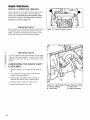
TRACTION DRIVE LOCK
When Pushing the Snowthrower:
For easy turning when pushing the snowthrower,
disengage the right wheel using the traction lock pin
(See Figure 11.)
1. Turn the unit off, remove the engine key, and
disconnect the spark plug wire.
2. To DISENGAGE the traction drive lock, insert the
Traction Lock Pin (A, Figure 11) through the outer
hole in the right axle. The unit can now be pushed
with minimal resistance.
3. To ENGAGE the traction drive lock, align the hole
in the hub with the inner hole in the axle, and
install the Traction Lock Pin (B).
NOTE: Be sure both wheels are locked (locking pin in
inner hole) when clearing snow.
©
/
/
/
/
Figure 9. Deflector Control
A. Maximum Throwing Position
B. Minimum Throwing Position
C. Deflector Adjustment Knob
®
Figure 10. Skid Shoe Adjustment
A. Scraper Bar
B. Skid Shoe
C. Nuts
Figure 11. Traction Drive Lock
A. Pin in Outer Hole (Freewheel)
B. Pin in inner Hole (Drive)
18

CLEARING A CLOGGED
DISCHARGE CHUTE
Hand contact with the rotating auger/impeller inside
the discharge chute is the most common cause of
injury associated with snowthrowers. DO NOT use
your hand to clean out the discharge chute. To clear
the chute:
1. Stop the engine. Remove the key
2. Wait 10 seconds to be sure the auger/impeller
blades have stopped rotating.
3. Use the clean-out tool to remove clogs. DO NOT
use your hands.
Operation
, WARNING
Never store the unit, with gasoline in engine or
fuel tank, in a heated shelter or in enclosed,
poorly ventilated enclosures. Gasoline fumes
may reach an open flame, spark or pilot light
(such as a furnace, water heater, clothes dryer,
etc.) and cause an explosion.
Handle gasoline carefully. It is highly
flammable and careless use could result in
serious fire damage to your person or property.
Drain fuel into an approved container outdoors
away from open flame or sparks.
AFTER EACH USE
Normal use of the snowthrower may result in a build-
up of packed snow in and around the starter cord
housing and around engine controls. Heat from the
engine will usually prevent the snow from freezing
solid while the unit is running, but after the engine is
shut down, some snow may continue melting from
engine heat, and later freeze around some moving
parts as the unit cools.
After each period of use, follow these steps to prevent
freeze-up caused by ice formation in and around the
engine controls and external parts.
1. Before shutting off the engine, pull the starter rope
out 2 - 3 times, and allow it to rewind slowly. This
will help clear packed snow from the starter cord
area. Allow the engine to run for several minutes.
2. Stop the engine by pushing the stop switch (C,
Figure 2) to the off position then pull out the
engine key (D, Figure 2).
3. Brush snow and ice from the snowthrower. Be
sure to clear engine and snowthrower controls,
discharge chute, and chute rod gears, clutch cable
areas, and anywhere else snow has accumulated.
4. Always remove the engine key and store in a safe
place to prevent unauthorized use.
,WARNING
Never store the unit (with fuel) in an enclosed,
poorly ventilated structure. Fuel vapors can
travel to an ignition source (such as a furnace,
water heater, etc.) and cause an explosion.
Fuel vapor is also toxic to humans and
animals.
5. If the snowthrower is kept in a cold shelter, fill the
fuel tank to prevent condensation. Do not store
near sparks or flame.
Note: The Engine Owner's Manual contains further
information on preventing ice formation and freeze-up.
STORAGE
WARNING
Never store the unit (with fuel) in an enclosed,
poorly ventilated structure. Fuel vapors can
travel to an ignition source (such as a furnace,
water heater, etc.) and cause an explosion.
Fuel vapor is also toxic to humans and
animals.
Before you store your unit for the off-season, read the
Maintenance and Storage instructions in the Safety
Rules section, then perform the following steps:
• Perform engine maintenance and storage
measures listed in the engine owner's manual.
This includes draining the fuel system, or adding
stabilizer to the fuel (do not store a fueled unit in
an enclosed structure - see warning).
Before starting the unit after it has been stored:
• Check all fluid levels. Check all maintenance
items.
• Perform all recommended checks and procedures
found in the engine owner's manual.
• Allow the engine to warm up for several minutes
before use.
O
,'--4-
O
19

Beg
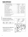
MAINTENANCE SCHEDULE
MAINTENANCE REQUIRED
Check / Lubricate Hand Linkage.
Lubricate snowthrower.
Check tire pressure.
Change engine oil.*+
Clean or replace spark plug.+
Check drive linkage/belt tension.
Lubricate Axle Shafts.
Check auger gear case lubrication.**
Lubricate Auger Shaft.***
* Changeoriginal oil after two hoursof operation.
** Checkgrease leveleach fall and spring.
+ See your engine Owner's Manual.
***Lubricate each fall and spring.
FREQUENCY NOTES
10 Hours 10W Oil
10 Hours 10W Oil and Grease
Monthly 20 psi (1.37 bar)
50 Hours; See Engine Manual
Yearly See Engine Manual
4-6 Hours See page 24
Yearly Lithium Grease
25 Hours Benalene Grease
10 Hours Lithium Grease
O
t-
0_
c
(D
c
c_
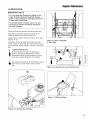
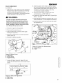
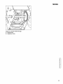
CHECKING TIRE PRESSURE
The air pressure in each tire (Figure 12) should be
equal for both tires for best performance. Be sure to
keep caps on valves to prevent entry of debris into the
valve stem when tires are filled.
Size PSI bar
13 x 5.0 20 1,37
AUGER GEAR CASE LUBRICATION
1. Place the snowthrower on a level surface.
2. Remove the bolt (A, Figure 13).
3. Check the lubricant level. It should be level with
the lower edge of the plug opening. If not, add
Benalene grease.
4. Re-install bolt, and tighten securely.
Figure 12. Checking Tire Pressure
Figure 13. Auger Lubrication
A. Bolt
I
b
2O
Page is loading ...
Page is loading ...
Page is loading ...
Page is loading ...
Page is loading ...
Page is loading ...
Page is loading ...
Page is loading ...
Page is loading ...
Page is loading ...
Page is loading ...
Page is loading ...
Page is loading ...
Page is loading ...
Page is loading ...
Page is loading ...
Page is loading ...
Page is loading ...
-
 1
1
-
 2
2
-
 3
3
-
 4
4
-
 5
5
-
 6
6
-
 7
7
-
 8
8
-
 9
9
-
 10
10
-
 11
11
-
 12
12
-
 13
13
-
 14
14
-
 15
15
-
 16
16
-
 17
17
-
 18
18
-
 19
19
-
 20
20
-
 21
21
-
 22
22
-
 23
23
-
 24
24
-
 25
25
-
 26
26
-
 27
27
-
 28
28
-
 29
29
-
 30
30
-
 31
31
-
 32
32
-
 33
33
-
 34
34
-
 35
35
-
 36
36
-
 37
37
-
 38
38


Simplicity 1695411 Owner's manual
- Category
- Snow throwers
- Type
- Owner's manual
Ask a question and I''ll find the answer in the document
Finding information in a document is now easier with AI
Related papers
-
Simplicity SIMPLICITY DUAL STAGE SNOWTHROWER, 9.0 TP, 24 INCH User manual
-
-
-
Briggs & Stratton SNW, DS, STEERABLE User guide
-
-
-
Simplicity SNOWTHROWER, DS CRAFTSMAN MD CANADA User manual
-
-
-
Other documents
-
-
 Craftex CT103N Owner's manual
-
-
Snapper 520E User manual
-
Murray 1695886 User manual
-
-
-
-
-
