Crestron IM-FTCC-M Installation guide
- Category
- PC/workstation barebones
- Type
- Installation guide
This manual is also suitable for

Crestron IM-FTCC-M
iMedia Fliptop Computer Center
Operations & Installation Guide

This document was prepared and written by the Technical Documentation department at:
Crestron Electronics, Inc.
15 Volvo Drive
Rockleigh, NJ 07647
1-888-CRESTRON
All brand names, product names and trademarks are the property of their respective owners.
©2007 Crestron Electronics, Inc.

Crestron IM-FTCC-M iMedia FlipTop Computer Center
Contents
iMedia FlipTop Computer Center: IM-FTCC-M 1
Introduction ..........................................................................................................1
Features and Functions...........................................................................1
Applications ...........................................................................................3
Internal Block Diagram..........................................................................4
Specifications .........................................................................................4
Physical Description...............................................................................5
Industry Compliance ............................................................................10
Setup...................................................................................................................11
Network Wiring ...................................................................................11
IM Wiring ............................................................................................11
Installation............................................................................................12
Hardware Hookup ................................................................................17
Operation............................................................................................................19
Problem Solving.................................................................................................20
Troubleshooting ...................................................................................20
Reference Documents ..........................................................................20
Further Inquiries...................................................................................21
Future Updates .....................................................................................21
Appendix: International Receptacles..................................................................22
Return and Warranty Policies.............................................................................23
Merchandise Returns / Repair Service .................................................23
CRESTRON Limited Warranty ...........................................................23
Operations & Installation Guide – DOC. 6610A Contents • i


Crestron IM-FTCC-M iMedia FlipTop Computer Center
Operations & Installation Guide – DOC. 6610A iMedia FlipTop Computer Center: IM-FTCC-M • 1
iMedia FlipTop Computer Center:
IM-FTCC-M
Introduction
Crestron's iMedia provides an extremely simple and affordable multimedia
presentation solution for small conference rooms and training rooms. No
comparable solution comes close to matching iMedia's speed and ease of
installation, intuitive operation, and incredibly low cost.
The IM-FTCC-M (120 VAC version) and the IMI-FTCC-M (220 VAC version)
are functionally identical, except for the power requirements. References
throughout the manual to the IM-FTCC-M apply equally to both units unless
specified otherwise.
Features and Functions
•
Flush-mount tabletop computer interface
• Streamlined user controls for foolproof operation
• iMedia Transport for fast and easy single cable installation
• Supports XGA resolution up to 84 feet (25.6 m), UXGA
maximum up to 34 feet (10.4 m)
• Easy pull-out cables and AC power outlet
• One iMedia RJ-45 output connector (on the bottom side)
• Power on/off SELECT button and indicator
• Rotary volume control adjusts local level as well as level for
wireless microphone (wireless microphone input is located on the
IM-RXV1-M or IM-RXV3-M)
• Lid flips open 180 degrees for easy access
• Includes cable management kit with VGA and audio cables
•
Com
p
lete s
y
stem setu
p
in minutes usin
g
iMedia Wizard Software

iMedia FlipTop Computer Center Crestron IM-FTCC-M
The iMedia Transport
The iMedia (IM) transport utilizes a single CAT5e* type cable to transmit
computer RGB, video, and stereo audio signals to a single projector or plasma
display. A typical XGA signal (1024 X 768 pixels at 60 Hz) can be transmitted
up to 84 feet (25.6 m) using iMedia, while higher resolutions up to 1600 x 1200
can be handled over shorter distances. Audio is transmitted digitally at 20-bit, 48
kHz resolution. Control and power signals are also contained on the same wire,
eliminating the need for separate control or power cables.
* For optimum performance, Crestron strongly recommends using CRESCAT-IM cable,
available from Crestron. Other high-quality/low skew (15 ns per 100 m maximum)
CAT5e/CAT6 wiring may also be used with varying performance.
FlipTop Computer Interface
The IM-FTCC-M is an iMedia transmitter designed to install flush in a tabletop
surface to provide a convenient and low profile interface solution. Beneath the
"FlipTop" lid, a recessed compartment contains easy pull out RGB and audio
cables to facilitate the connection of a single computer source. The cables stow
neatly within the compartment when not in use. Excess cable simply drops out
of sight below the box through grommeted holes provided in the bottom plate.
An additional hole is available to accommodate a third party LAN cable if
needed.
For complete connectivity, the IM-FTCC-M also includes an AC power
receptacle. Installing wiring for the IM-FTCC-M is extremely simple requiring
just a single CresCAT-IM cable for audio and video. Up to three IM-FTCC-Ms,
or other IM transmitters, may be installed as part of a complete system to
provide multiple input locations within the room.
Foolproof Operation
Every iMedia system is easy and intuitive to use. A single press of the large
SELECT button inside the compartment lowers the screen or lift, turns on the
projector (or plasma, etc.) and routes the connected computer signal to the
appropriate input. The front panel volume control affords easy adjustment of the
audio level, or wireless microphone level, and the entire system can be turned
off at any time by simply holding the SELECT button for five seconds.
For systems having more than one IM transmitter, selecting an input at a given
input location overrides the previously selected input at any other location. The
audio level for each input location is controlled individually by its respective
volume control.
2 • iMedia FlipTop Computer Center: IM-FTCC-M Operations & Installation Guide - DOC. 6610A

Crestron IM-FTCC-M iMedia FlipTop Computer Center
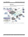
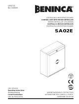
Applications
The IM-FTCC-B is an IM transmitter. As shown in the following diagram, IM
transmitters provide input points for video and PC sources on an IM receiver.
Typical Installation for Media Presentation (IM-FTCC-M is shown at Bottom)
Operations & Installation Guide – DOC. 6610A iMedia FlipTop Computer Center: IM-FTCC-M • 3

iMedia FlipTop Computer Center Crestron IM-FTCC-M
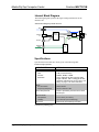
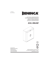
Internal Block Diagram
The following diagram represents the signal routing and functions of the
IM-FTCC-M.
Internal Block Diagram of the IM-FTCC-M
SELECT
LED
VOLUME
BUTTON
VGA
COMPUTER
AUDIO
IM
Output
A/D
Power
Supply
Power
Micro-
processor
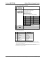
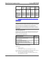
Specifications
Specifications for the IM-FTCC-M are given in the following table.
IM-FTCC-M Specifications
SPECIFICATION DETAILS
RGB
Gain
Formats
Resolution
0 dB (75 Ω termination)
RGBHV, RGBS, or RG
s
B
1024 x 768 @ 60 Hz with maximum cable
length of 84 feet, 1600 x 1200 @ 60 Hz with
maximum cable length of 34 feet; refer to “IM
Wiring” on page 11 for other resolutions
Audio
A-D Conversion
Frequency Response
20-bit, 48 kHz
20 Hz to 20 kHz ±1 dB
Power Requirements
Power is provided by the IM receiver via the
IM transport
Environmental
Temperature
Humidty
41º to 104º F (5º to 40º C)
10 to 90% RH (non-condensing)
Enclosure Black metal; flush tabletop mountable
(Continued on following page)
4 • iMedia FlipTop Computer Center: IM-FTCC-M Operations & Installation Guide - DOC. 6610A

Crestron IM-FTCC-M iMedia FlipTop Computer Center
IM-FTCC-M Specifications (Continued)
SPECIFICATION DETAILS
Dimensions
IM-FTCC-M
Height
Width
Depth
4.63 in (11.76 cm) with lid closed
6.84 in (17.38 cm)
5.62 in (14.28 cm) without mounting brackets
IMI-FTCC-M
Height
Width
Depth
5.43 in (13.79 cm) with lid closed
8.34 in (21.19 cm)
6.20 in (15.74 cm) without mounting brackets
Weight
IM-FTCC-M
IMI-FTCC-M
3.65 lbs (1.66 kg) with cables
4.42 lbs (2.01 kg) with cables
International Adaptors for
IMI-FTCC-M Models
Refer to “Appendix: International
Receptacles” on page 22
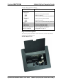
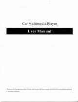
Physical Description
This section provides information on the connections, controls and indicators
available on your IM-FTCC-M.
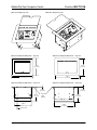
IM-FTCC-M Physical View
Operations & Installation Guide – DOC. 6610A iMedia FlipTop Computer Center: IM-FTCC-M • 5

iMedia FlipTop Computer Center Crestron IM-FTCC-M
IM-FTCC-M Open Top View IMI-FTCC-M Open Top View
SELECT
IM-FTCC-M Physical Dimensions – Top View IMI-FTCC-M Physical Dimensions – Top View
5.
62 in
(
14.
28 cm)
6
.
84
in
(1 7. 3 8
cm
)
6.20
in
(
15.74 cm
)
8.
34
in
(21.
19 cm)
IM-FTCC-M Physical Dimensions – Front View IMI-FTCC-M Physical Dimensions – Front View
Rests on
Table
Surface
0.14 in
(0.36 cm)
4.49 in
(11.41 cm)
5.38 in
(13.67 cm)
Power Cord
6.88 in
(17.48 cm)
0.14 in
(0.36 cm)
5.
29
in
(13.44 cm)
6 • iMedia FlipTop Computer Center: IM-FTCC-M Operations & Installation Guide - DOC. 6610A

Crestron IM-FTCC-M iMedia FlipTop Computer Center
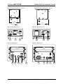
IM-FTCC-M Physical Dimensions – Side View IMI-FTCC-M Physical Dimensions – Side View
4.19 in
(10.65 cm)
Power Cord
4.77 in
(12.11 cm)
IM-FTCC-M Front Face View IMI-FTCC-M Front Face View
SELECT
1
2
3
1
2
3
IM-FTCC-M Bottom View IMI-FTCC-M Bottom View
4 5 6 7 8 4 5 6 7 8
Operations & Installation Guide – DOC. 6610A iMedia FlipTop Computer Center: IM-FTCC-M • 7

iMedia FlipTop Computer Center Crestron IM-FTCC-M
Connectors, Controls & Indicators
# CONNECTORS,
CONTROLS &
INDICATORS
DESCRIPTION
1 125VAC 10A
(1) 3-prong grounded AC socket, AC
power pass-thru outlet;
Maximum Load: 10 Amps @ 125 Volts
AC, 50/60 Hz.
250V 10A
(1) 3-prong grounded AC socket, AC
power pass-thru outlet;
Specify socket type (refer to “Appendix:
International Receptacles” on page 22);
Maximum Load: 10 Amps @ 250 Volts
AC, 50/60 Hz.
2 SELECT
SELECT
(1) Pushbutton with green LED;
Momentary press initiates “system power
on” command and selects local
COMPUTER input; press and hold for 5
seconds or more initiates “system power
off”.
3 VOLUME
(1) Rotary knob, adjusts audio levels for
local input. Microphone level is adjusted
by holding the SELECT button and
turning the VOLUME knob.
4 125V
(1) 6 ft grounded AC line cord;
Passes through to front panel AC power
outlet.
MAX 250V
(1) IEC socket;
Passes through to front panel AC power
outlet.
5 AUDIO
(1) 3.5mm TRS mini phone jack;
Unbalanced stereo line-level audio input;
Maximum input level: 2 V
rms
;
Input impedance: 10 kΩ;
Connects to 6 ft mini-TRS audio patch
cable (included).
6 IM
1, 2, 3
(1) 8-wire RJ-45 female, iMedia output
port;
Connects to IM input port of an iMedia
receiver via CresCAT-IM cable.
(Continued on following page)
8 • iMedia FlipTop Computer Center: IM-FTCC-M Operations & Installation Guide - DOC. 6610A

Crestron IM-FTCC-M iMedia FlipTop Computer Center
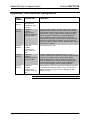
Connectors, Controls & Indicators (Continued)
# CONNECTORS,
CONTROLS &
INDICATORS
DESCRIPTION
7
COMPUTER
PIN 1
PIN 6
PIN 15
(1) DB15HD female, RGB(VGA) input;
Formats: RGBHV, RGBS, RG
s
B;
Input impedance: 75 Ω;
Sync impedance: 1 kΩ;
Maximum input level: 1 V
p-p
;
Maximum sync level: 5 V
p-p
;
Connects to 6 ft VGA patch cable (included).
PIN FUNCTION PIN FUNCTION
1 Red Video 9 No Connect
2 Green Video 10 Ground
3 Blue Video 11 No Connect
4 Reserved 12 Monitor Sense 1
5 Ground 13 Horizontal Sync
6 Red Ground 14 Vertical Sync
7 Green Ground 15 Monitor Sense 2
8 Blue Ground
8 GROUND
(1) 6-32 screw, chassis ground lug
4
.
1. The eight-pin RJ-45 iMedia port accepts CresCAT-IM or CAT5E/CAT6 carrying video, audio,
power and control signals. Refer to the following table for connector pinouts. Power is supplied to
pins 4 and 5 from the IM receivers.
PIN WIRE COLORS (EIA 568B)
iMEDIA ASSIGNMENT:
RGB AND AUDIO
1 WHITE/ORANGE
- RGB RED
2 ORANGE
+ RGB RED
3 WHITE/GREEN
- RGB GREEN
4 BLUE
+ AUDIO / POWER
5 WHITE/BLUE
- AUDIO / POWER
6 GREEN
+ RGB GREEN
7 WHITE/BROWN
- RGB BLUE
8 BROWN
+ RGB BLUE
2. For optimum performance, Crestron strongly recommends using CRESCAT-IM cable, available
from Crestron. Other high-quality/low skew (15 ns per 100 m maximum) CAT5e/CAT6 wiring may
also be used with varying performance.
3. To determine which is pin 1 on the cable, hold the cable so that the end of the eight pin modular jack
is facing away from you, with the clip down and copper side up. Pin 1 is on the far left.
4. Ensure that the unit is properly grounded.
Operations & Installation Guide – DOC. 6610A iMedia FlipTop Computer Center: IM-FTCC-M • 9

iMedia FlipTop Computer Center Crestron IM-FTCC-M
Industry Compliance
As of the date of manufacture, the IM-FTCC-M has been tested and found to
comply with specifications for CE marking and standards per EMC and
Radiocommunications Compliance Labelling.
NOTE: This device complies with part 15 of the FCC rules. Operation is subject
to the following two conditions: (1) this device may not cause harmful
interference, and (2) this device must accept any interference received, including
interference that may cause undesired operation.
This equipment has been tested and found to comply with the limits for a Class B
digital device, pursuant to part 15 of the FCC Rules. These limits are designed to
provide reasonable protection against harmful interference in a residential
installation. This equipment generates, uses and can radiate radio frequency energy
and, if not installed and used in accordance with the instructions, may cause
harmful interference to radio communications. However, there is no guarantee that
interference will not occur in a particular installation. If this equipment does cause
harmful interference to radio or television reception, which can be determined by
turning the equipment off and on, the user is encouraged to try to correct the
interference by one or more of the following measures:
Reorient or relocate the receiving antenna.
Increase the separation between the equipment and receiver.
Connect the equipment into an outlet on a circuit different from that to which the
receiver is connected.
Consult the dealer or an experienced radio/TV technician for help.
10 • iMedia FlipTop Computer Center: IM-FTCC-M Operations & Installation Guide - DOC. 6610A

Crestron IM-FTCC-M iMedia FlipTop Computer Center
Setup
Network Wiring
When wiring the network, consider the following:
• Use Crestron Certified Wire.
• Use Crestron power supplies for Crestron equipment.
• Provide sufficient power to the system.
CAUTION: Insufficient power can lead to unpredictable results or
damage to the equipment.
IM Wiring
Using a proprietary signal routing solution, RGBHV, audio, power and control
signals are all transported using a single cable solution called iMedia.
The iMedia transport system port is capable of managing computer RGB and
audio signals simultaneously through one CresCAT-IM cable, simplifying
installations.
Routing CresCAT-IM cable (low-skew CAT5e) is less expensive and a much
simpler solution for wiring iMedia systems than routing multi-colored,
multi-conductor coax cable. All Crestron products using the iMedia transport
system are capable of sending and receiving iMedia signals via CresCAT-IM
cable. Installation of any iMedia device is as simple as installing one iMedia
cable from output to input. Installations are affordable and fast.
The receiver can accomplish frequency compensation on each input to achieve
correct operation. This compensation scheme is effective for CresCAT-IM
cables as long as the maximum skew of 15 ns per 100 meters is not exceeded.
NOTE: For optimum performance, Crestron strongly recommends using
CRESCAT-IM cable, available from Crestron. Other high-quality/low skew
(15 ns per 100 m maximum) CAT5e/CAT6 wiring may also be used with
varying performance.
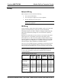
Maximum Resolution and Cable Length
RESOLUTION REFRESH
RATE
(HZ)
PIXEL
RATE
(MHZ)
PIXEL
TIME (NS)
MAX
LENGTH
(FEET)
VGA 60 25.18 39.7 218.5
(640 X 480) 72 31.50 31.7 174.6
85 36.00 27.8 152.8
SVGA 56 36.00 27.8 152.8
(800 X 600) 72 50.00 20.0 110.0
85 56.25 17.8 97.8
XGA 60 65.00 15.4 84.6
(1024 X 768) 70 75.00 13.3 73.3
85 94.50 10.6 58.2
(Continued on following page)
Operations & Installation Guide – DOC. 6610A iMedia FlipTop Computer Center: IM-FTCC-M • 11

iMedia FlipTop Computer Center Crestron IM-FTCC-M
Maximum Resolution and Cable Length (Continued)
RESOLUTION REFRESH
RATE
(HZ)
PIXEL
RATE
(MHZ)
PIXEL
TIME (NS)
MAX
LENGTH
(FEET)
SXGA 60 108.00 9.3 50.9
(1280 X 1024) 75 135.00 7.4 40.7
85 157.50 6.3 34.9
UXGA 60 162.00 6.2 34.0
(1600 X 1200) 70 189.00 5.3 29.1
85 229.50 4.4 24.0
COMPOSITE
VIDEO
218.5
For more information on CresCAT and other wire products, visit the Crestron
website (www.crestron.com/downloads/pdf/product_line_overviews/overview-
wire_and_cable.pdf).
Installation
NOTE: To prevent overheating, do not operate this product in an area that
exceeds the environmental temperature range listed in the table of specifications.
Consideration must be given if installed in a closed or multi-unit rack assembly,
inside a closed desk or in a closed podium since the operating ambient
temperature of these rack environments may be greater than the room ambient
temperature. Contact with thermal insulating materials should be avoided on all
sides of the unit.
Cable Management Kit
The IM-FTCC-M is shipped with a cable management kit that includes a cable
management plate, a 6-foot VGA cable, a 6-foot audio cable, and associated
hardware as listed in the following table.
Parts Supplied with Cable Management Kit
PART DESCRIPTION QUANTITY
Small Cable Bushing, 5/16” ID, 0.5” OD 2
Large Cable Bushing, 0.55” ID, 0.80” OD 1
Cable Support Plate 1
4-40 x ¼ inch Phillips Head Screws 4
Computer RGB Cable, VGA to VGA, 6 ft long 1
Computer Audio Cable, 3.5 mm Stereo, 6 ft long 1
Tie Wraps 3
Complete the following instructions for installation.
Tools Required
• Phillips screwdriver
• Small flat blade screwdriver (for connecting the VGA cable)
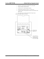
The cable support plate must be installed before mounting the IM-FTCC-M to a
surface. The cables are looped through the cable support plate.
1. Place the bushings on the cables (three bushings supplied). Use the
large bushing for the VGA cable.
12 • iMedia FlipTop Computer Center: IM-FTCC-M Operations & Installation Guide - DOC. 6610A

Crestron IM-FTCC-M iMedia FlipTop Computer Center
2. Thread the cables through the appropriate slots on the plate.
3. Snap the bushings into the plate slots.
4. Feed all the excess cable through the opening.
5. Attach the plate using the four #4-40 x ¼” black screws.
6. Connect the cables to the appropriate connectors on the bottom of the
IM-FTCC-M.
7. The cables may be secured to the bottom bar using tie wraps.
Cable Plate Installation (IM-FTCC-M Shown)
Screws (4)
#4-40 x ¼”
Large Bushing
Small Bushing
Operations & Installation Guide – DOC. 6610A iMedia FlipTop Computer Center: IM-FTCC-M • 13

iMedia FlipTop Computer Center Crestron IM-FTCC-M
Cable Loops Through the Cable Plate (IM-FTCC-M Shown)
Allow approximately
40 inches for cable clearence
RGB Cable
Audio Cable
Power Cord
NOTE: Ensure that the cables have sufficient clearance to enable smooth
movement. Allow approximately 40 inches (102 cm) from the top surface of the
FlipTop box mounting to surface.
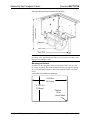
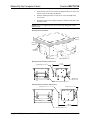
Mounting to Surface
The IM-FTCC-M is designed to mount in a horizontal surface, such as a desk
top, lectern, or podium. The following diagram illustrates the required opening
size to accommodate the IM-FTCC-M. Use the supplied template to make the
cutout.
Cutout Dimensions for IM-FTCC-M (4007291)
65/16in
(161 mm
)
4 11/16 in
(118 mm)
Radius
1/8 in
(4 mm) Max
14 • iMedia FlipTop Computer Center: IM-FTCC-M Operations & Installation Guide - DOC. 6610A

Crestron IM-FTCC-M iMedia FlipTop Computer Center
Cutout Dimensions for IMI-FTCC-M (4007909)
Radius
1/8in
(
4
mm
)
51/8in
(131 mm)
713/16in
(198 mm )
NOTE: Before inserting the IM-FTCC-M in the mounting hole, ensure that all
required cables have been installed.
Mounting Parts Supplied with the IM-FTCC-M
PART DESCRIPTION QUANTITY
Screw #6-32, Pan Head, Phillips 4
Screw #10-32, Pan Head, Phillips 4
Mounting Bracket 2
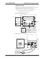
1. Install the four supplied #6-32 screws, but do not tighten (four screws
on the rear are installed). All eight screws are used to secure the front
and rear mounting brackets.
2. Position the IM-FTCC-M in the mounting hole.
Mounting Bracket Screw Locations
#6-32 Screws
#6-32 Screws
Surface
Cutout
Screws (4)
#6-32 x 3/16“
Surface
Cutout
Screws (4)
#6-32 x 3/16“
Operations & Installation Guide – DOC. 6610A iMedia FlipTop Computer Center: IM-FTCC-M • 15

iMedia FlipTop Computer Center Crestron IM-FTCC-M
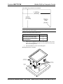
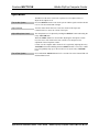
3. Install the four #10-32 screws in the mounting brackets (two screws per
bracket). Refer to the following diagram.
4. Slide the mounting brackets over the #6-32 screws and tighten the
#6-32 screws.
5. Turn the four #10 screws equally until they contact the underside of the
mounting surface.
NOTE: Do not over-tighten the #10 screws as this may damage the surface
and/or the unit.
Mounting Bracket Installation
Mounting
Bracket
Screws (2)
#10-32 x 2"
Mounting Bracket
Screws (2) #10-32 x 2"
Mounting
Surface
Mounting Brackets Installed - IM-FTCC-M
(4)
#10-
32 x 2
"
SCREWS
6. 77 in
(17. 20 cm)
MOUNTING BRACKETS (2)
SCREWS (8)
#6-32 x 3/16"
Mounting Brackets Installed - IMI-FTCC-M
7. 34 in
(18. 64 cm)
MOUNTING BRACKETS (2)
(4)
#10-
32 x 2
"
SCREWS
SCREWS (8) #6-32 x 3/16"
16 • iMedia FlipTop Computer Center: IM-FTCC-M Operations & Installation Guide - DOC. 6610A
Page is loading ...
Page is loading ...
Page is loading ...
Page is loading ...
Page is loading ...
Page is loading ...
Page is loading ...
Page is loading ...
-
 1
1
-
 2
2
-
 3
3
-
 4
4
-
 5
5
-
 6
6
-
 7
7
-
 8
8
-
 9
9
-
 10
10
-
 11
11
-
 12
12
-
 13
13
-
 14
14
-
 15
15
-
 16
16
-
 17
17
-
 18
18
-
 19
19
-
 20
20
-
 21
21
-
 22
22
-
 23
23
-
 24
24
-
 25
25
-
 26
26
-
 27
27
-
 28
28


Crestron IM-FTCC-M Installation guide
- Category
- PC/workstation barebones
- Type
- Installation guide
- This manual is also suitable for
Ask a question and I''ll find the answer in the document
Finding information in a document is now easier with AI
Related papers
-
Crestron IMI-FTCC-B Installation guide
-
-
-
-
-
-
-
-
-
Other documents
-
 Peerless Lighting Cord Manager Installation guide
-
ATEN 2X-031G Quick start guide
-
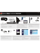 DigiSender iMedia SmartSender Quick Manual
-
Packard Bell DT.U8EEG.005 Datasheet
-
Ideal 85-372 Operating instructions
-
-
 Beninca SA02E Owner's manual
-
 Beninca DA96AE User guide
-
 Crestron electronic TPS Series User manual
-
 Chinavision CVABR-C389 User manual


