Smeg A4-6 Datasheet

Category
Cookers
Type
Datasheet

This manual is also suitable for

Smeg A4-6 is a multifunctional gas and electric appliance with a multitude of cooking and baking options. Equipped with a gas hob featuring different burner sizes and capacities, including a rapid burner for fast cooking and a fish burner for delicate dishes. The electric ovens offer various cooking functions, including traditional baking, grilling, and a dedicated "Pizza" function for crispy homemade pizzas. The appliance also includes a storage compartment for conveniently storing cookware and accessories.

Smeg A4-6 is a multifunctional gas and electric appliance with a multitude of cooking and baking options. Equipped with a gas hob featuring different burner sizes and capacities, including a rapid burner for fast cooking and a fish burner for delicate dishes. The electric ovens offer various cooking functions, including traditional baking, grilling, and a dedicated "Pizza" function for crispy homemade pizzas. The appliance also includes a storage compartment for conveniently storing cookware and accessories.

Table of Contents
1. PRECAUTIONS FOR SAFETY AND USE ___________________________ 46
2. INSTALLING THE APPLIANCE ___________________________________ 48
3. ADAPTATION TO DIFFERENT TYPES OF GAS______________________ 51
4. FINAL OPERATIONS ___________________________________________ 53
5. DESCRIPTION OF CONTROLS___________________________________ 55
6. USING THE HOB ______________________________________________ 62
7. USING THE OVENS ____________________________________________ 64
8. USING THE "PIZZA" FUNCTION __________________________________ 65
9. ACCESSORIES AVAILABLE _____________________________________ 67
10. COOKING ADVICE _____________________________________________ 69
11. CLEANING AND MAINTENANCE _________________________________ 75
12. EXTRAORDINARY MAINTENANCE _______________________________ 81
THESE INSTRUCTIONS ONLY APPLY TO THE COUNTRIES OF DESTINATION WHOSE
IDENTIFICATION SYMBOLS ARE LISTED ON THE COVER OF THIS MANUAL.
INSTRUCTIONS FOR THE INSTALLER: these are intended for the
qualified engineer who is to check the gas supply system and install,
commission and test the appliance.
INSTRUCTIONS FOR THE USER: these provide recommendations for
use, a description of the controls and the correct procedures for
cleaning and maintaining the appliance.
45
Presentation
1. PRECAUTIONS FOR SAFETY AND USE
THIS MANUAL IS AN INTEGRAL PART OF THE APPLIANCE. TAKE GOOD
CARE OF IT AND KEEP IT TO HAND THROUGHOUT THE COOKER'S LIFE
CYCLE. USERS ARE ADVISED TO READ THIS MANUAL AND ALL THE
INSTRUCTIONS IT CONTAINS BEFORE USING THE COOKER. ALSO KEEP
THE SET OF NOZZLES PROVIDED IN A SAFE PLACE. INSTALLATION MUST
BE CARRIED OUT BY QUALIFIED STAFF IN COMPLIANCE WITH THE
RELEVANT REGULATIONS. THIS APPLIANCE IS INTENDED FOR
HOUSEHOLD USE AND COMPLIES WITH THE EEC DIRECTIVES CURRENTLY
IN FORCE. THE APPLIANCE IS BUILT TO PROVIDE THE FOLLOWING
FUNCTION: COOKING AND HEATING FOODS; ALL OTHER USES ARE TO BE
CONSIDERED IMPROPER.
THE MANUFACTURER DECLINES ALL LIABILITY FOR USES OTHER THAN
THOSE STATED ABOVE.
NEVER LEAVE PACKAGING RESIDUES UNATTENDED IN THE HOME.
SEPARATE WASTE PACKAGING MATERIALS BY TYPE AND CONSIGN THEM
TO THE NEAREST SEPARATE DISPOSAL CENTRE.
THE APPLIANCE MUST BE CONNECTED TO EARTH IN COMPLIANCE WITH
ELECTRICAL SYSTEM SAFETY REGULATIONS.
THE PLUG TO BE CONNECTED TO THE POWER SUPPLY LEAD AND THE
RELATIVE SOCKET MUST BE OF THE SAME TYPE AND COMPLY WITH THE
RELEVANT REGULATIONS.
THE POWER SUPPLY SOCKET MUST BE ACCESSIBLE EVEN AFTER THE
APPLIANCE HAS BEEN BUILT-IN.
NEVER DISCONNECT THE PLUG BY PULLING ON THE POWER SUPPLY
LEAD.
IMMEDIATELY AFTER INSTALLATION, CARRY OUT A QUICK TEST ON THE
APPLIANCE FOLLOWING THE INSTRUCTIONS PROVIDED LATER IN THIS
MANUAL. IF THE APPLIANCE FAILS TO OPERATE, DISCONNECT IT FROM
THE ELECTRICAL MAINS AND CONTACT YOUR NEAREST SERVICE CENTRE.
NEVER ATTEMPT TO REPAIR THE APPLIANCE YOURSELF.
AFTER EACH USE OF THE APPLIACE, ALWAYS CHECK THAT THE CONTROL
KNOBS ARE TURNED TO
(OFF).
NEVER PLACE FLAMMABLE OBJECTS IN THE OVENS: IF THEY SHOULD
ACCIDENTALLY BE SWITCHED ON, THIS MIGHT CAUSE A FIRE.
46
Presentation
THE NAMEPLATE WITH THE TECHNICAL DATA, SERIAL NUMBER AND MARK
IS IN A VISIBLE POSITION IN THE STORAGE COMPARTMENT.
THE NAMEPLATE MUST NEVER BE REMOVED.
NEVER PLACE PANS WITH BOTTOMS WHICH ARE NOT PERFECTLY FLAT
AND SMOOTH ON THE HOB PAN STANDS.
THE APPLIANCE BECOMES VERY HOT DURING USE. TAKE CARE NOT TO
TOUCH THE HEATING ELEMENTS INSIDE THE OVEN.
THIS APPLIANCE MUST NEVER BE INSTALLED ON A STAND.
INSTALL THE APPLIANCE SO THAT WHEN DRAWERS OR DOORS OF UNITS
INSTALLED AT HOB HEIGHT ARE OPENED, ACCIDENTAL CONTACT WITH
PANS ON THE HOB IS NOT POSSIBLE.
NEVER USE PANS OR GRIDDLE PLATES WHICH PROJECT BEYOND THE
OUTSIDE EDGE OF THE HOB.
THE APPLIANCE IS INTENDED FOR USE BY ADULTS. KEEP CHILDREN AT A
SAFE DISTANCE AND NEVER ALLOW THEM TO PLAY WITH IT.
THIS APPLIANCE IS TAGGED UNDER EUROPEAN DIRECTIVE 2002/96/EC ON
WASTE ELECTRICAL AND ELECTRONIC EQUIPMENT (WEEE).
THIS DIRECTIVE CONTAINS THE REGULATIONS GOVERNING THE
COLLECTION AND RECYCLING OF DECOMMISSIONED APPLIANCES
THROUGHOUT THE EUROPEAN UNION.
BEFORE THE APPLIANCE IS PUT INTO OPERATION, ALL THE LABELS AND
PROTECTIVE FILMS APPLIED INSIDE OR OUTSIDE MUST BE REMOVED.
The manufacturer declines all responsibility for injury or damage
caused by failure to comply with the above regulations or deriving from
tampering with even just one part of the appliance and the use of non-
original spare parts.
47
Instructions for the Installer
48
2. INSTALLING THE APPLIANCE
Installation must be carried out by a qualified engineer in compliance
with the relevant regulations.
It may be installed against walls one of which is higher than the worktop
surface, at least 50 mm from the side of the appliance, as shown in the
installation class drawings A and B. Wall units or extractor hoods
installed above the appliance's work-top must be at least 750 mm above
it.
A
B
Built-in Appliance Free-Standing Installation
2.1 Positioning and levelling the appliance
The appliance is equipped with wheels and adjustable feet to simplify the
positioning procedure. To use the front wheels, screw in the foot as
shown here, so that the appliance rests on the front wheels. However, to
allow the appliance to be moved freely it must be lifted at the back. To
do this, proceed as follows:
use a 10 socket wrench to screw in
the 2 hex nuts underneath the oven
compartment: this raises the
appliance either to level it or to
allow it to be moved around.
Once all procedures are complete,
retighten the front feet and the hex
nuts to set the cooker stable and
level.
Instructions for the Installer
2.2 Electrical connection
Check that the voltage and size of the power supply line are as specified
on the nameplate inside the storage compartment.
This nameplate must never be removed.
The plug on the end of the power supply cable and the wall socket must
be of the same type (in compliance with the relevant national standards).
Check that the power supply line is properly earthed. The use of
reductions, adapters or junctions is not recommended.
The appliance's power supply line must be fitted with an omnipolar
breaking device with contact gap of at least 3 mm, located in an easily
accessible position close to the appliance itself.
The appliance has a terminal board on
its rear.
To access it, remove the back cover.
Make the electrical connection in
accordance with the wiring diagram
shown below.
Operation at 380-415V3N~: use a H05RR-F
or H05RN-F five-wire cable (cable of 5 x 1.5
mm2).
Operation at 380-415V2N~: use a H05RR-F
or H05RNF four-wire cable (cable of 4 x 2.5
mm2).
Operation at 220-240 V~: use a H05RR-F /
H05RNF three-wire cable (cable of 3 x 6
mm2).
The earth wire (yellow-green) must be at
least 20 mm longer than the other wires at
the end for connection to the appliance.
The manufacturer declines all responsibility for injury or damage
caused by failure to comply with the above regulations or deriving from
tampering with even just one part of the appliance.
49
Instructions for the Installer
50
2.3 Ventilation requirements
The room containing the appliance should have an air supply in accordance with
B.S. 5440 part 2 1989.
1. All rooms require an opening window or equivalent, and some rooms will
require a permanent vent as well.
2. For room volumes up to 5 m
3
an air vent of 100 cm
2
is required.
3. If the room has a door that opens directly to the outside, and the room
exceeds 1 m
3
no air vent is required.
4. For room volumes between 5 m
3
and 10 m
3
an air vent of 50 cm
2
is required.
5. If there are other fuel burning appliances in the same room B.S. 5440 part 2
1989 should be consulted to determine the air vent requirements.
6. This appliance must not be installed in a bed sitting room of less than 20 m
3
or in a bathroom or shower room.
Windows and permanent vents should therefore not be blocked or removed
without first consulting a Corgi gas installer.
Failure to install appliances correctly is dangerous and could lead to
prosecution.
Connecting to natural and LPG gas (Please see connection
diagram)
2.4
Make the connection to the appliance using flexible bayonet
style hose in accordance to B.S. 669. The hose connection at
the rear of the appliance has a 1/2" BSP internal thread.
Please use seal C between the flexible connection L and the
appliance supply tube B. When making the connection, make
sure that no stress of any kind is applied to the cooker and
that the hose does not touch any sharp edges.
If connecting to LPG the bayonet hose must have red
bands on it.
Instruction for wall fixing (only on some models) 2.5
1) Fix the screw to the wall and hook the chain (B);
2) Hook the chain to the hole positioned at the rear of the cooker by the gas
pipe (A);
3) Once the chain is in position, push the cooker against the wall;
4) The height of the screw hole from floor level must not exceed 800 mm (C).
A
B
C
Instructions for the Installer
3. ADAPTATION TO DIFFERENT TYPES OF GAS
Before performing any cleaning or maintenance work, switch off the
power supply to the appliance.
The cooking hob of the cooker is preset for G20 natural gas at a
pressure of 20 mbar. In the case of functioning with other types of gas the
burner nozzles must be changed and the minimum flame adjusted on the
gas taps. Replace the burner nozzles as indicated in the table of the gas
to be used.
Changing nozzles 3.1
1. Extract the grids and remove all the caps and flame-spreader
crowns;
2. unscrew the burner nozzles with a 7 mm socket wrench;
3. proceed with replacing the burner nozzles in accordance with the
table for the gas in question.
51
Instructions for the Installer
52
3.2
Burner and nozzle characteristics table
Burner
Rated
heating
capacity
(kW)
LPG G30/G31 28/37 mbar
(drawing ref. X238)
Nozzle
diameter
1/100 mm
By-pass
Mm
1/100
Reduced
flowrate
(W)
Flowrate
g/h G30
Flowrate
g/h G31
Auxiliary 1.05 50 30 400 76 75
Semi rapid 1.8 65 33 500 131 129
Rapid 3.0 85 45 800 218 215
Fish Burner 1.9 68 45 800 138 136
Ultra rapid 4.0 100 65 1600 291 286
Burner
Rated
heating
capacity
(kW)
NATURAL GAS – G20 20 mbar
Nozzle diameter
1/100 mm
Drawing
Ref.
Reduced flowrate
(W)
Auxiliary 1.05 72 (X) 400
Semi rapid 1.8 97 (Z) 500
Rapid 3.0 115 (Y) 800
Fish Burner 1.9 94 (X) 800
Ultra rapid 4.0 135 (K) 1600
3.3 Hob burner layout
BURNERS
1 Auxiliary
2 Semi rapid
3 Rapid
4 Ultra rapid
5 Fish
Instructions for the Installer
4. FINAL OPERATIONS
After changing the nozzles, put the pan stands, the burner caps and
flame diffuser rings back in place.
After adjusting for use of a gas other than the gas used for testing the
appliance, replace the gas setting label on the appliance with the label
for the new gas. The label is supplied in the bag with the nozzles.
4.1 Adjusting the minimum setting for town gas and natural
gas
Light the burner and turn it to the minimum
setting
Remove the gas tap knob and adjust the
regulator screw inside or beside the tap rod
(depending on the model) until an even minimum
flame is obtained. Put the knob back in place and
check the stability of the burner flame (the flame
must not go out when the knob is turned quickly
from the maximum to the minimum setting). Repeat
the operation on all the gas taps.
4.2 Adjusting the minimum for bottled gas
To adjust the minimum level when using bottled gas, the adjuster screw
inside or beside the tap rod must be turned fully clockwise (depending on
the models).
The diameters of the bypasses for each individual burner are stated in
point "3.2 Burner and Nozzle Data Tables".
53
Instructions for the Installer
54
4.3
Fitting the rear splash-back
Place the splash-back on the hob, aligning the holes A with the holes
B.
Fix the splash-back to the hob by tightening the screws C.
Instructions for the User
5.1
5. DESCRIPTION OF CONTROLS
The front panel
All the cooker's control and monitoring devices are placed together on the
front panel.
At first use after a power blackout, press the middle knob for 1 / 2
seconds to enable oven cooking operations.
KEY TO SYMBOLS
FRONT LEFT-HAND
BURNER
REAR LEFT-HAND
BURNER
FRONT CENTRAL
BURNER
REAR CENTRAL BURNER
FRONT RIGHT-HAND
BURNER
REAR RIGHT-HAND
BURNER
BARBECUE ELEMENT
RIGHT-HAND OVEN
TIMER
LEFT-HAND
OVEN THERMOSTAT
RIGHT-HAND
OVEN THERMOSTAT
LEFT-HAND OVEN
FUNCTIONS
RIGHT-HAND OVEN
FUNCTIONS
LEFT-HAND OVEN THERMOSTAT KNOB
The cooking temperature is selected by turning the knob
clockwise to the required setting, between 50° and 250°C.
The light comes on to indicate that the oven is heating up.
This light goes out when the set temperature is reached.
When it flashes at regular intervals, the temperature inside
the oven is being kept constantly at the set level.
55
Instructions for the User
56
LEFT-HAND OVEN FUNCTION SELECTOR KNOB
Turn the knob to select one of the following functions:
NO FUNCTION SET
GRILL ELEMENT + FAN
TOP AND BOTTOM
HEATING ELEMENTS
TOP AND BOTTOM
HEATING ELEMENTS + FAN
BOTTOM HEATING ELEMENT
+ FAN
GRILL ELEMENT
BOTTOM HEATING ELEMENT +
FAN HEATING ELEMENT
FAN HEATING ELEMENT + FAN
DEFROSTING
HOB BURNER CONTROL KNOB
To light the flame, press the knob and turn it anti-
clockwise to the maximum flame symbol . To adjust
the flame, turn the knob to the zone between the
maximum and the minimum settings. To turn off
the burner, turn the knob to the position.
BARBECUE ELEMENT POWER REGULATOR
KNOB
This knob is used to set the power of the barbecue
griddle on the hob. Turn the knob to any setting
between “1” and “9” to switch on the heating element.
The light comes on to indicate that the element is
heating up.
To switch off the element, return the knob back to the
“0” setting.
WARNING: after it has been in operation for some time, the griddle
remains hot even after the heating element has been switched off:
keep children at a safe distance.
Instructions for the User
RIGHT-HAND OVEN THERMOSTAT KNOB
The cooking temperature is set by turning the knob
clockwise to the value required, between 50° and 280°
( )C.
The light comes on to indicate that the oven is heating
up. This light goes out when the set temperature is
reached. When it flashes at regular intervals, the
temperature inside the oven is being kept constantly at
the set level.
RIGHT-HAND OVEN FUNCTION SELECTOR KNOB
Turn the knob to select one of the following functions:
NO FUNCTION SET
GRILL ELEMENT + FAN
TOP AND BOTTOM
HEATING ELEMENTS
GRILL ELEMENT
TOP AND BOTTOM
HEATING ELEMENTS + FAN
PIZZA FUNCTION
BOTTOM HEATING ELEMENT
+ FAN
RIGHT OVEN TIMER KNOB
Allows to select manual cooking or the minute minder;
the oven switches off automatically at the end of
cooking.
If no selection of a cooking duration is made, the
timer knob must be positioned on the symbol
57
Instructions for the User
58
5.2 Electronic Analogue Clock
LIST OF FUNCTIONS
MINUTE-MINDER BUTTON
END OF COOKING BUTTON
CLOCK ADJUSTMENT AND RESET
VALUE DECREASE BUTTON
VALUE INCREASE BUTTON
5.2.1 Setting the time
When the oven is used for the first time, or after an interruption in the
electricity supply, the display flashes at regular intervals. Press the
key for 1 / 2 seconds to stop the display flashing and start the procedure
for setting the current time. Press the value modification keys or to
increase or decrease the setting by one minute for each pressure.
Press one of the two value modification keys until the current time
appears. 6/7 seconds after the last key is pressed, the clock will start
from the time set.
At the end of each programmed operation 8 beeps will sound 3/4 times
at intervals of about 1 and a half minutes. This sequence can be stopped
at any time by pressing any key.
Instructions for the User
5.2.2 Minute-Minder
- This function does not stop cooking; it simply
activates the buzzer. Press the
key and the
display will light up as shown in figure 1;
1
2
- Within 6/7 seconds, press the or keys to
set the minute-minder. Each time a key is
pressed, 1 outside segment, representing 1
minute of cooking time, will light up or go out.
(figure 2 shows a cooking time of 10 minutes).
- 6/7 seconds after the last key is pressed, the
countdown will start; when it finishes, the buzzer
will sound.
- During the countdown, the current time can be
viewed by pressing the
key once; press it
again to return to the minute minder display.
- At the end of the countdown, the oven must
be switched off manually by turning the
thermostat and function selector knob to 0.
59
Instructions for the User
60
5.2.3 Programming
Cooking duration: the 2nd button
can be pressed to set the cooking
duration. Before it can be set, the thermostat must be turned to the
cooking temperature required and the function selector knob to any
setting. To set the cooking duration, proceed as follows:
- Press the
key for 1 / 2 seconds; the pointer will
locate on 12 (Fig. 1).
- Use the and keys to set the cooking
duration: each pressure on the key adds 1
minute to the cooking duration, and every 12
minutes a new inside segment will light up (figure
2 shows a cooking duration of 1 hour).
- Once the duration required is obtained, cooking
will start about 6 seconds after the last pressure
on
of .
- Once cooking has started the display will show the
current time, represented by the constantly
illuminated segments, and the minutes left to the
end of the cooking time, represented by the
flashing segments (each flashing segment means
12 minutes of cooking time left).
1
2
- At the end of the cooking time the timer will switch the oven heating
elements off, the beeps will start to sound and the numbers on the
dial will flash.
- The duration can also be reset by resetting the program selected:
pressing the central key
for 1 or 2 seconds will delete the duration
set and the oven will have to be switched off in manual mode.
Caution: it is not possible to set cooking durations of more than 6
hours.
Instructions for the User
Starting cooking: as well as setting a cooking duration, the cooking start
time can also be set (with a maximum delay of 12 hours from the current
time). To set the cooking start/end time, proceed as follows:
- Set the cooking duration as described in the previous point.
- Within 6/7 seconds of the last pressure on the
or keys, press
the key again to set the cooking start time. The current time will
appear on the display with internal segments illuminated to show the
end of cooking time. Use the and keys to set the cooking
start time.
- 6/7 seconds after the last key is pressed, the display will show the
current time and the cooking start and end times, which will be
represented by the illuminated inside segments. The display
segments will be constantly illuminated as long as the current time is
not the same as the cooking start time; as soon as the current time
reaches the set starting time, all the inside segments will start to
flash, indicating that the oven has started cooking.
- At the end of the cooking time the timer will switch the oven heating
elements off, the beeps will start to sound and the numbers on the
dial will flash.
- To reset the whole program set, keep the central key
pressed for
1 or 2 seconds: if cooking has already started, the oven will have to
be switched off by hand.
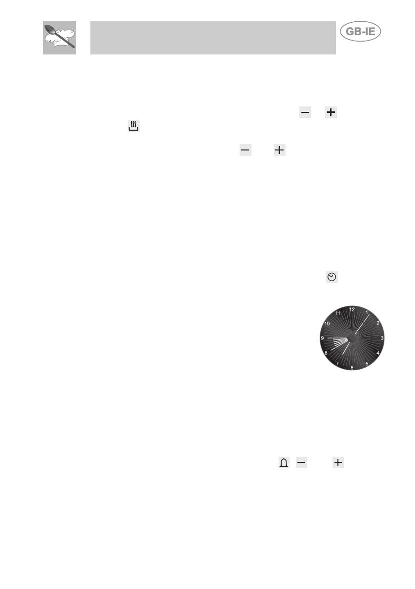
- Here we can see a programming example: the
current time is 7:06 and cooking is programmed to
start at 8:00 and end at 9:00.
- At 8 o'clock the inside segments between 8 and 9
will start to flash, while the hours hand will remain
still.
Caution: for the oven to start cooking operations after the
programming procedures just described, the thermostat and
function selector knob must correctly set on the temperature and
function required.
5.2.4 "DEMO" Function
Models with analogue/digital programmer feature a "DEMO" function
which deactivates the heating elements while leaving the other functions
unchanged. To activate it, simply press the
, , and keys and
keep them held down for 3-4 seconds. A confirmation buzzer will inform
the user that the function is active. When the “DEMO” function is active,
the number 6 on the clock flashes at regular intervals. To deactivate it,
simply repeat the same procedure.
61
Instructions for the User
62
6.1
6. USING THE HOB
Lighting the hob burners
Before lighting the hob burners check that the flame diffuser rings are
correctly in place with their respective burner caps, making sure that the
holes A in the flame diffusers are aligned with the plugs and thermocouples.
The special pan stand B is for use with woks.
The burner it controls is shown next to each knob. The appliance is
equipped with an electronic ignition device. Simply press the knob and turn
it anti-clockwise to the maximum flame symbol
, until the burner lights.
Keep the knob pressed down for about 2 seconds to allow the thermocouple
to heat up. The burner may go out when the knob is released: this means
that the thermocouple has not warmed up enough. Repeat the operation,
keeping the knob pressed down for longer.
If the burners should go out accidentally a safety device will be tripped
about 20 seconds later, cutting off the gas supply even if the gas tap is
open.
Instructions for the User
6.2 Practical hints for using the hob burners
For better burner efficiency and to minimise gas consumption, use pans
with lids of suitable size for the burner, so that flames do not reach up
the sides of the pan (see point "6.3 Pan Diameters"). Once the contents
come to the boil, turn down the flame far enough to prevent the liquid
from boiling over. When cooking, to prevent burns or damage to the hob
all pans or griddle plates must be placed inside the perimeter of the hob.
All pans must have smooth, flat bottoms. Take the greatest care when
using fats or oils since they may catch fire if overheated. If the flame
accidentally goes out, turn off the control knob and wait at least 1 minute
before trying to re-light the burner.
6.3 Pan diameters
BURNERS
1 Auxiliary
2 Semi rapid
3 Rapid
4 Ultra rapid
5 Fish
min. and max. Ø
(in cm)
12-14
16-24
18-26
20-26
Special oval pans
6.4 Using the barbecue griddle
This griddle plate has a non-stick (Teflon) coating. The non-
stick film is very delicate and may be damaged if metal
utensils are used.
Use only utensils made from wood or plastic resistant
to high temperatures.
63
Instructions for the User
64
7.1
7. USING THE OVENS
Precautions and General Advice
When the oven is used for the first time, it should be heated to the
maximum temperature (250-220°C) for long enough to burn off any oily
residues left by the manufacturing process, which might contaminate
foods with unpleasant smells.
If both ovens are in use at the same time, there may be problems with
delicate cooking processes.
During cooking, do not cover the bottom of the oven with aluminium or
tin foil, and do not place pans or trays on it; this may damage the enamel
coating. If you wish to use greaseproof paper, position it so that it does
not interfere with the hot air circulation inside the oven.
To avoid unpleasant contact with any steam
inside the oven, open the door in two stages:
hold it half-open (about 5 cm) for 4-5 seconds,
then open it completely. If you have to carry out
any procedures on foods, leave the door open
for as short a time as possible to prevent a drop
in the oven temperature which will impair the
cooking results.
5 cm
7.2
7.3
7.4
Oven light
It comes on when the function selector is turned to any setting.
Cooling fan system
The appliance is equipped with a cooling system, which comes into
operation as soon as a cooking function is selected. This is also the case
for cooking with the minute minder.
Fans cause a steady outflow of air from the rear top skirtboard on the
rear of the cooking hob, which may continue for a brief period of time
even after the oven has been turned off.
This ventilation system ensures that the temperatures on the outside of
the appliance meet the standards required by the current regulations.
Storage compartment
The storage compartment is in the bottom of
the cooker, underneath the ovens. To open
it, pull on the top of the door. Never use it to
store flammable materials such as rags,
paper, etc.; it is intended to take the
appliance's metal accessories only.
  • Page 1 1
  • Page 2 2
  • Page 3 3
  • Page 4 4
  • Page 5 5
  • Page 6 6
  • Page 7 7
  • Page 8 8
  • Page 9 9
  • Page 10 10
  • Page 11 11
  • Page 12 12
  • Page 13 13
  • Page 14 14
  • Page 15 15
  • Page 16 16
  • Page 17 17
  • Page 18 18
  • Page 19 19
  • Page 20 20
  • Page 21 21
  • Page 22 22
  • Page 23 23
  • Page 24 24
  • Page 25 25
  • Page 26 26
  • Page 27 27
  • Page 28 28
  • Page 29 29
  • Page 30 30
  • Page 31 31
  • Page 32 32
  • Page 33 33
  • Page 34 34
  • Page 35 35
  • Page 36 36
  • Page 37 37
  • Page 38 38

Smeg A4-6 Datasheet

Category
Cookers
Type
Datasheet
This manual is also suitable for

Smeg A4-6 is a multifunctional gas and electric appliance with a multitude of cooking and baking options. Equipped with a gas hob featuring different burner sizes and capacities, including a rapid burner for fast cooking and a fish burner for delicate dishes. The electric ovens offer various cooking functions, including traditional baking, grilling, and a dedicated "Pizza" function for crispy homemade pizzas. The appliance also includes a storage compartment for conveniently storing cookware and accessories.

Ask a question and I''ll find the answer in the document

Finding information in a document is now easier with AI