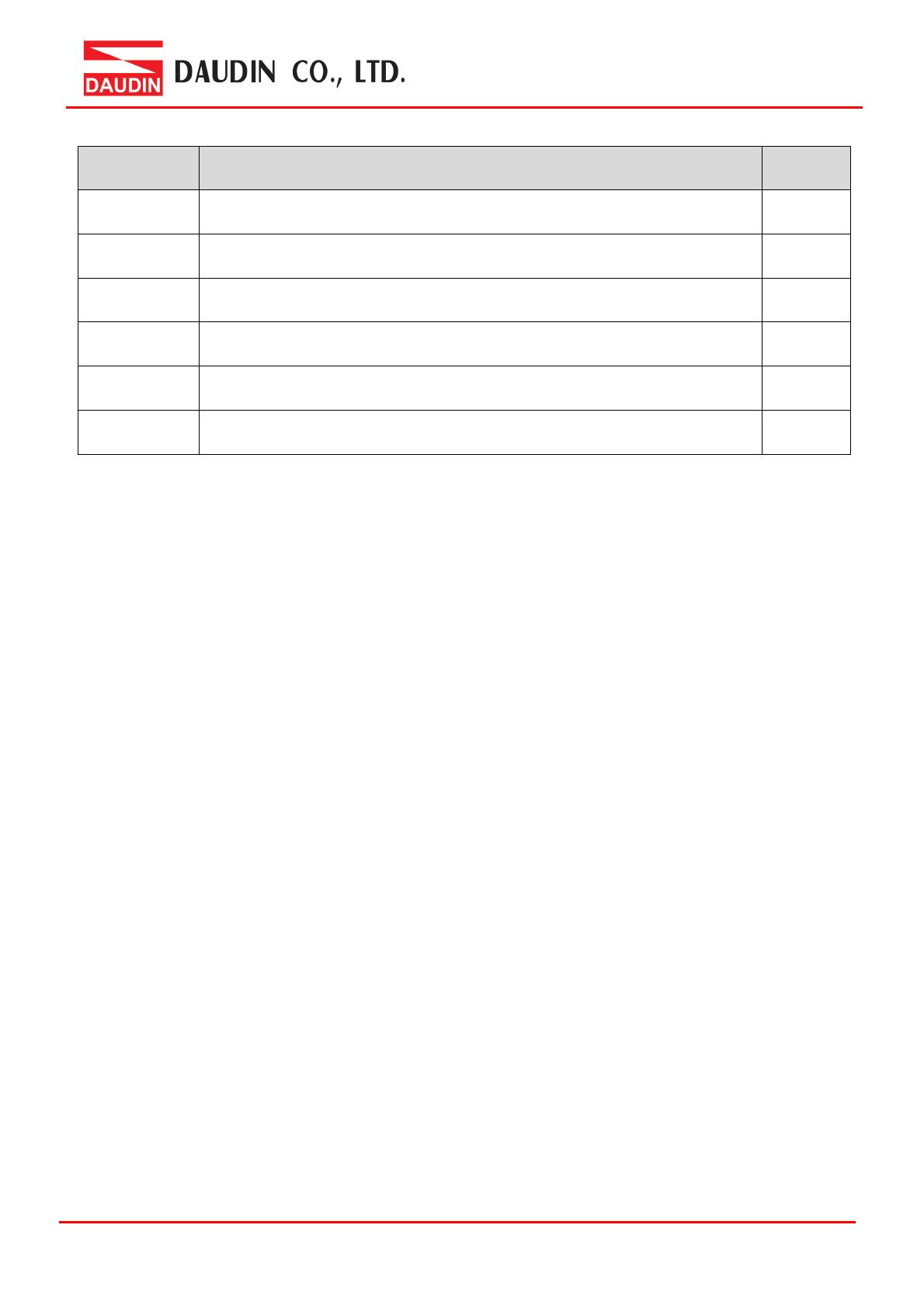
1. Example Remote I/O Module System Configuration List
Part No. Specification Remarks
GF2-C004T PROFINET Coupler
GF2-DI01T 16-channel digital input module, Sink, 24VDC
GF2-DQ01T 16-channel digital output module, Sink, 24VDC
GF2-AI01T 4-channel analog input module (-10… 10VDC, 0…10VDC,0...5VDC)
GF2-AQ01T 4-channel analog output module (-10… 10VDC, 0…10VDC,0...5VDC)
GFPS-0202 Power 24V / 48W
1.1 Product Description
I. The coupler connects to the communication port (PROFINET) on Siemens S7-120
II. The coupler is in charge of the management and dynamic configuration of I/O
parameters and so on.
III. The power module is standard for remote I/Os and users can choose the model or
brand of power module they prefer.


