TECHNICAL DATA
Hardware
Power supply Exchangeable power supply unit (110–230 V, 50–60 Hz)
Power consumption max. 105 watts
Environment Temperature range 0–40°C, humidity 10–90%; non-condensing
Housing Robust metal housing, 19“ 1U (442 x 44 x 375 mm > W x H x D),
network connectors on the front
Number of fans 2 exchangeable fan modules
Interfaces
SFP-DD 4 * SFP-DD (25 / 50 Gbps) stacking ports
QSFP+ / SFP28 2 * QSFP+ (40 Gbps) / 4 * SFP28 (10 / 25 Gbps) FleX uplink ports for connecting higher-level
core switches, content servers, or data centers
SFP+ / TP-Ethernet
Combo-Ports
Each 4 * SFP+ (1 / 10 Gbps) / TP-Ethernet (1 / 2.5 / 5 / 10 Gbps) combo ports for use as
additional downlink ports or for connection to a NAS or router
SFP+ 16 * SFP+ (1 / 10 Gbps) downlink ports for aggregation of subordinate access switches
Console 1 * RJ-45 / 1 * Micro USB
USB 1 * USB
Declaration of Conformity
Hereby, LANCOM Systems GmbH | Adenauerstrasse 20/B2 | D-52146 Wuerselen, declares that this device is in
compliance with Directives 2014/30/EU, 2014/35/EU, 2011/65/EU, and Regulation (EC) No. 1907/2006. The full text of
the EU Declaration of Conformity is available at the following Internet address: www.lancom-systems.com/doc
Package Content
Documentation Quick Reference Guide (DE/EN), Installation Guide (DE/EN)
Mounting material Rack mounting system consisting of 2 mounting brackets for front mounting and 2 slide-in
rails for optional rear mounting of the switch in the rack.
Power supply 1x exchangeable power supply LANCOM SPSU-250
(expandable to 2 exchangeable power supplies for redundancy operation)
Fan modules 2 fan modules LANCOM SFAN-XS6, already mounted
Cables 1 IEC power cord, 1 serial configuration cable, 1 micro USB configuration cable
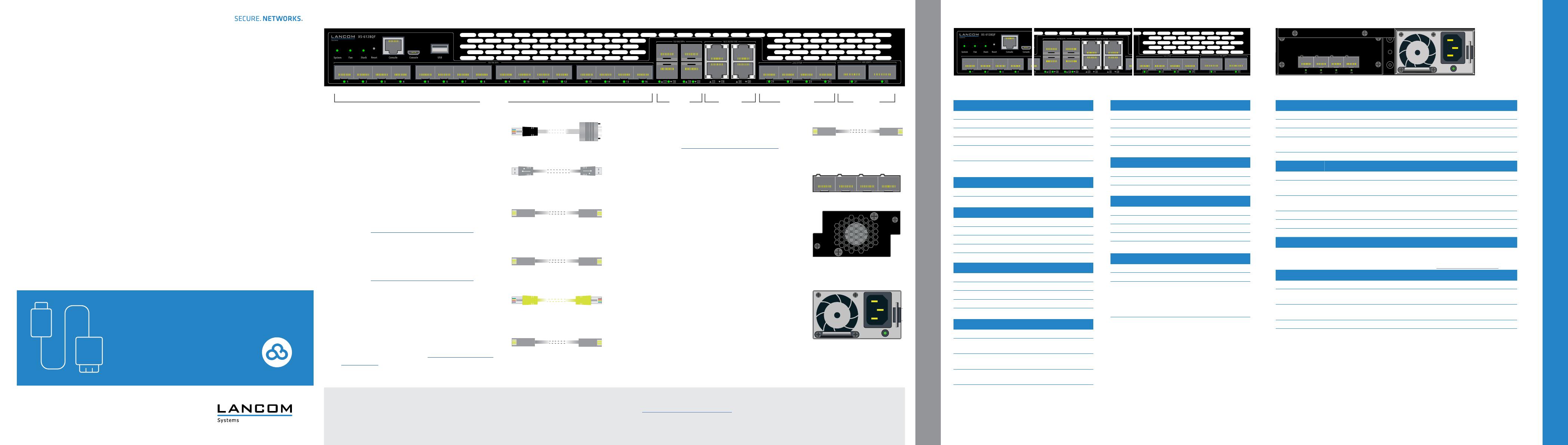
MOUNTING AND CONNECTING THE DEVICE
c SFP+ ports 1G / 10 G
Off Port inactive or disabled
Green Link 10 Gbps
Green, blinking Data transfer, link 10 Gbps
Orange Link 1 Gbps
Orange, blinking Data transfer, link 1 Gbps
a
b
Configuration interfaces RJ-45 & micro USB (Console)
Connect the configuration interface a via the included serial
configuration cable to the serial interface of the device you want to use
for configuring / monitoring the switch. Alternatively use the interface
b with a suitable micro USB cable.
cUSB interface
Connect a USB stick to the USB interface to store general configuration
scripts or debug data.
You can also use this interface to upload a new firmware.
dSFP+ interfaces 1G / 10G
Insert suitable LANCOM SFP modules into the SFP+ interfaces 1
to 12. Choose cables which are compatible with the SFP modules
and connect them as described in the SFP modules mounting
instructions www.lancom-systems.com/SFP-module-MI.
eSFP+ interfaces 1G / 10G (combo ports)
Insert suitable LANCOM SFP modules into the SFP+ interfaces 13
to 14. Choose cables which are compatible with the SFP modules
and connect them as described in the SFP modules mounting
instructions www.lancom-systems.com/SFP-module-MI.
fTP Ethernet interfaces 1G / 2.5G / 5G / 10G (combo ports)
Connect the interfaces 13 to 14 via Ethernet cables to your PC or a LAN
switch.
gSFP28 interfaces 10G / 25G (FleX ports)
Insert suitable LANCOM SFP28 or 10G SFP+ modules into the SFP28
interfaces 21 to 24. Choose cables which are compatible with the
SFP28 / 10G SFP+ modules and connect them as described in the
SFP modules mounting instructions www.lancom-systems.com/
SFP-module-MI.
hQSFP+ interfaces 40G (FleX ports)
Plug suitable LANCOM QSFP+ modules into the QSFP+
interfaces 21 to 22. Select cables suitable for the QSFP+ modules
and connect them as described in the SFP modules mounting
instructions www.lancom-systems.com/SFP-module-MI.
Device back side:
SFP-DD interfaces 25G / 50G
Insert LANCOM SFP-DD-DAC50 stacking cables into the SFP-DD
interfaces 25 to 28. For decentralized stacking scenarios
(stack-member switches are distributed over spatially separated
locations) the use of LANCOM SFP28 modules is recommended.
2 slots for fan modules
To remove a fan module in case of defect, loosen the two knurled
screws of the module and remove the module from the plug-in
unit.
To install a new fan module, push it into the corresponding slot.
Fasten the module to the switch housing with the knurled screws.
Please note that a defective fan should be replaced within 48h.
2 slots for power supply modules with mains connection
socket
To install a power supply module, remove the appropriate module
slot cover by loosening both associated screws and insert the
power supply module.
Supply the device with voltage via the power supply module mains
connector. Use the supplied power cord (not for WW devices) or a
country -specific LANCOM power cord.
To remove a power supply module, disconnect the device from the
power supply and pull the power plug out of the module. Then
push the release lever I to the left. Now you can pull the module
out of the device by the handle J.
LANCOM XS-6128QF
Quick Reference Guide
Cloud-ready
b Reset button
~5 sec. pressed Device restart
7~12 sec. pressed Configuration reset and device restart
a System / Fan / Stack
System: green Device operational
System: red Hardware error
Fan: red Fan error
Stack: off No connection
Stack: green As master device: port activated and
connected to slave device
Stack: orange As slave device: port activated and con-
nected to master device
LANCOM, LANCOM Systems, LCOS, LANcommunity and Hyper Integration are registered trademarks. All other names or descriptions used may be trademarks or registered trademarks of their owners. This docu-
ment contains statements relating to future products and their attributes. LANCOM Systems reserves the right to change these without notice. No liability for technical errors and / or omissions. 111947/12/21
e TP Ethernet ports 1G / 2.5G / 5G / 10G (combo ports)
Off Port inactive oder disabled
Green Left LED: Link 10 Gbps
Right LED: Link 1 Gbps
Green, blinking Left LED: Data transfer, link 10 Gbps
Right LED: Data transfer, link 1 Gbps
Orange Left LED: Link 2.5 / 5 Gbps
Right LED: Link 100 Mbps
Orange, blinking Left LED: Data transfer, link 2.5 / 5 Gbps
Roght LED: Data transfer, link 100 Mbps
g QSFP+ ports 40G (FleX ports)
Off Port inactive or disabled
Green Link 40 Gbps
Green, blinking Data transfer, link 40 Gbps
d SFP+ ports 1G / 10G (combo ports)
Off Port inactive or disabled
Green Link 10 Gbps
Green, blinking Data transfer, link 10 Gbps
Orange Link 1 Gbps
Orange, blinking Data transfer, link 1 Gbps
Please observe the following when setting up the device
AThe mains plug of the device must be freely accessible.
ADo not rest any objects on top of the device.
AKeep the ventilation slots of the device clear of obstruction.
AMount the device with the enclosed rack mounting system in a free 19” slot of an appropriate server rack.
Both slide-in rails are attached as shown in the accompanying installation instructions
www.lancom-systems.com/slide-in-MI.
APlease note that support for third-party accessories (SFP and DAC) is not provided.
Before initial startup, please make sure to take notice of the information regarding the intended use in the enclosed installation guide!
Operate the device only with a professionally installed power supply at a nearby power socket that is freely accessible at all times.
i Power supply unit LED
Off No primary voltage supply
Green Secondary voltage supply OK
Orange Critical power supply event that causes a
shutdown: OCP, OVP, fan failure
In case of parallel primary voltage supply
by second power supply unit: power cable
disconnected or power failure
Orange, blinking Power supply warning event in which the
power supply continues to operate: high
temperature, high power, high current
consumption, slow fan
I
J
dc
ab
fe g h i
ab c
d e gf hf SFP28 ports 1G / 10G / 25G (FleX ports)
Off Port inactive oder disabled
Green Link 25 / 10 Gbps
Green, blinking Data transfer, link 25 / 10 Gbps
Orange Link 1 Gbps
Orange,blinking Data transfer, link 1 Gbps
h SFP-DD stacking ports 25G (SFP28) / 50G
Off Port inactive or disabled
Green Link 50 Gbps
Green, blinking Data transfer, link 50 Gbps
Orange Link 25 / 10 Gbps
Orange,blinking Data transfer, link 25 / 10 Gbps
