Page is loading ...

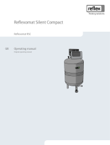
Variomat Giga with Touch controller 06.07.2016 - Rev. B
hydraulic modules:
GH 50 / GH 70 / GH 90 / GH 100
control modules
GS 1.1 / GS 3
GB
Operating manual
Original operating manual


Contents
Variomat Giga with Touch controller — 06.07.2016 - Rev. B English —
3
English
Variomat Giga with Touch controller
06.07.2016 - Rev. B
Contents
1
Notes on the operating manual..................................................................................................................................................... 5
2
Liability and guarantee................................................................................................................................................................... 5
3
Safety................................................................................................................................................................................................ 6
3.1 Explanation of symbols ........................................................................................................................................................................ 6
3.1.1 Symbols and notes used ................................................................................................................................................... 6
3.2 Personnel requirements ...................................................................................................................................................................... 7
3.3 Personal protective equipment .......................................................................................................................................................... 7
3.4 Intended use .......................................................................................................................................................................................... 7
3.5 Inadmissible operating conditions..................................................................................................................................................... 7
3.6 Residual risks ......................................................................................................................................................................................... 8
4
Description of the device................................................................................................................................................................ 9
4.1 Description ............................................................................................................................................................................................. 9
4.2 Overview ................................................................................................................................................................................................ 9
4.3 Identification ....................................................................................................................................................................................... 10
4.3.1 Nameplate ........................................................................................................................................................................ 10
4.3.2 Type code .......................................................................................................................................................................... 10
4.4 Function ............................................................................................................................................................................................... 11
4.5 Scope of delivery ................................................................................................................................................................................. 13
4.6 Optional equipment and accessories .............................................................................................................................................. 13
5
Technical data ............................................................................................................................................................................... 14
5.1 Control unit .......................................................................................................................................................................................... 14
5.2 Hydraulic module ................................................................................................................................................................................ 14
5.2.1 Dimensions and connections ........................................................................................................................................ 14
5.2.2 Pressures and mechanical assemblies.......................................................................................................................... 14
5.3 Tanks ..................................................................................................................................................................................................... 15
6
Installation ..................................................................................................................................................................................... 16
6.1 Installation conditions ....................................................................................................................................................................... 17
6.1.1 Incoming inspection ....................................................................................................................................................... 17
6.2 Preparatory work ................................................................................................................................................................................ 17
6.3 Execution .............................................................................................................................................................................................. 18
6.3.1 Positioning........................................................................................................................................................................ 18
6.3.2 Installation of add-on components for the tanks ....................................................................................................... 19
6.3.3 Tank installation .............................................................................................................................................................. 20
6.3.4 Hydraulic connection ...................................................................................................................................................... 21
6.3.5 Fitting the thermal insulation........................................................................................................................................ 26
6.3.6 Fitting the level sensor ................................................................................................................................................... 27
6.4 Make-up and degassing variants ..................................................................................................................................................... 28
6.4.1 Function ............................................................................................................................................................................ 28
6.5 Electrical connection .......................................................................................................................................................................... 34
6.5.1 Terminal plan, connection component ........................................................................................................................ 35
6.5.2 Terminal plan, operating unit ........................................................................................................................................ 37
6.5.3 RS-485 interface............................................................................................................................................................... 38
6.5.4 I/O module interface ....................................................................................................................................................... 40
6.6 Installation and commissioning certificate ..................................................................................................................................... 41
7
Commissioning.............................................................................................................................................................................. 42
7.1 Checking the requirements for commissioning ............................................................................................................................. 42
7.2 Determining the P0 minimum operating pressure for the controller ......................................................................................... 42

Contents
4 — English Variomat Giga with Touch controller — 06.07.2016 - Rev. B
7.3 Modifying the controller's start routine .......................................................................................................................................... 44
7.4 Filling the tanks with water............................................................................................................................................................... 47
7.4.1 Filling with a hose ........................................................................................................................................................... 47
7.4.2 Filling with the solenoid valve in the make-up .......................................................................................................... 47
7.5 Commissioning the pumps ............................................................................................................................................................... 48
7.6 Venting the pump .............................................................................................................................................................................. 49
7.6.1 Checking the pumps' direction of rotation ................................................................................................................. 49
7.6.2 Building up pump pressure ........................................................................................................................................... 50
7.6.3 Setting the pump delivery volume ............................................................................................................................... 50
7.7 Setting the minimum pressure limiter ............................................................................................................................................ 50
7.8 Parametrising the controller in the Customer menu .................................................................................................................... 51
7.9 Starting Automatic mode .................................................................................................................................................................. 51
8
Operation ...................................................................................................................................................................................... 52
8.1 Automatic mode ................................................................................................................................................................................. 52
8.2 Manual mode ...................................................................................................................................................................................... 53
8.3 Stop mode............................................................................................................................................................................................ 54
8.4 Summer operation.............................................................................................................................................................................. 55
8.5 Restarting ............................................................................................................................................................................................. 55
9
Controller ...................................................................................................................................................................................... 56
9.1 Operator panel .................................................................................................................................................................................... 56
9.2 Calibrating the touch screen ............................................................................................................................................................. 57
9.3 Configuring settings in the controller ............................................................................................................................................. 58
9.3.1 Customer menu ............................................................................................................................................................... 58
9.3.2 Service menu .................................................................................................................................................................... 61
9.3.3 Default settings ............................................................................................................................................................... 61
9.3.4 I/O module default setting ............................................................................................................................................. 62
9.3.5 Setting degassing programmes .................................................................................................................................... 64
9.3.6 Degassing programmes – overview ............................................................................................................................. 66
9.4 Messages .............................................................................................................................................................................................. 67
10
Maintenance ................................................................................................................................................................................. 71
10.1 Maintenance schedule ....................................................................................................................................................................... 72
10.2 External tightness and function test ................................................................................................................................................ 72
10.3 Cleaning the dirt trap ......................................................................................................................................................................... 73
10.4 Cleaning the tanks .............................................................................................................................................................................. 74
10.5 Checking switching points ................................................................................................................................................................ 75
10.6 Maintenance certificate ..................................................................................................................................................................... 77
10.7 Inspection ............................................................................................................................................................................................ 78
10.7.1 Pressure-bearing components ...................................................................................................................................... 78
10.7.2 Inspection prior to commissioning ............................................................................................................................... 78
10.7.3 Inspection intervals ......................................................................................................................................................... 78
11
Disassembly .................................................................................................................................................................................. 79
12
Annex ............................................................................................................................................................................................ 80
12.1 Reflex Customer Service .................................................................................................................................................................... 80
12.2 Conformity and standards ................................................................................................................................................................. 81
12.3 Certificate No. of the CE type test ..................................................................................................................................................... 82
12.4 Guarantee ............................................................................................................................................................................................ 82

Notes on the operating manual
Variomat Giga with Touch controller — 06.07.2016 - Rev. B English —
5
1
Notes on the operating manual
This operating manual is an important aid for ensuring the safe and reliable functioning of the device.
The operating manual will help you to:
• avoid any risks to personnel.
• become acquainted with the device.
• achieve optimal functioning.
• identify and rectify faults in good time.
• avoid any faults due to improper operation.
• cut down on repair costs and reduce the number of downtimes.
• improve the reliability and increase the service life of the device.
• avoid causing harm to the environment.
Reflex Winkelmann GmbH accepts no liability for any damage resulting from failure to observe the information in this operating manual.
In addition to the requirements set out in this operating manual, national statutory regulations and provisions in the country of
installation must also be complied with (concerning accident prevention, environment protection, safe and professional work practices,
etc.).
This operating manual describes the device with basic equipment and interfaces for optional equipment with additional functions. For
optional equipment and accessories, see chapter 4.6 "Optional equipment and accessories" on page 13 .
Note!
Every person installing this equipment or performing any other work at the equipment is required to carefully read this
manual prior to commencing work and to comply with its instruct
ions. The manual is to be provided to the device operator
and must be stored near the device for access at any time.
2
Liability and guarantee
The device has been built according to the state of the art and recognised safety rules. Nevertheless, its use can pose a risk to life and
limb of personnel or third persons as well as cause damage to the system or other property.
It is not permitted to make any modifications at the device, such as to the hydraulic system or the circuitry.
The manufacturer shall not be liable nor shall any warranty be honoured if the cause of any claim results from one or more of the
following causes:
• Improper use of the device.
• Unprofessional commissioning, operation, service, maintenance, repair or installation of the device.
• Failure to observe the safety information in this operating manual.
• Operation of the device with defective or improperly installed safety/protective equipment.
• Failure to perform maintenance and inspection work according to schedule.
• Use of unapproved spare parts or accessories.
Prerequisite for any warranty claims is the professional installation and commissioning of the device.
Note!
Arrange for Reflex Customer Service to carry out commissioning and annual
maintenance, see chapter 12.1 "Reflex
Customer Service
" on page 80 .

Safety
6
— English Variomat Giga with Touch controller — 06.07.2016 - Rev. B
3
Safety
3.1
Explanation of symbols
3.1.1
Symbols and notes used
The following symbols and signal words are used in this operating manual.
DANGER
• Danger of death and/or serious damage to health
• The sign, in combination with the signal word 'Danger', indicates imminent danger; failure to observe the safety information will
result in death or severe (irreversible) injuries.
WARNING
Serious damage to health
• The sign, in combination with the signal word 'Warning', indicates imminent danger; failure to observe the safety information can
result in death or severe (irreversible) injuries.
CAUTION
Damage to health
• The sign, in combination with the signal word 'Caution', indicates danger; failure to observe the safety information can result in
minor (reversible) injuries.
ATTENTION
Damage to property
• The sign, in combination with the signal word 'Attention', indicates a situation where damage to the product itself or objects within
its vicinity can occur.
Note!
This symbol, in combination with the signal word 'Note', indicates useful
tips and recommendations for efficient handling
of the product.

Safety
Variomat Giga with Touch controller — 06.07.2016 - Rev. B English —
7
3.2
Personnel requirements
Only specialist personnel or specifically trained personnel may install and operate the equipment.
The electric connections and the wiring of the device must be executed by a specialist in accordance with all applicable national and
local regulations.
3.3
Personal protective equipment
When working at the system, wear the stipulated personal equipment such as hearing and eye protection, safety boots, helmet,
protective clothing, protective gloves.
See the national regulation of your country for personal protective equipment required.
3.4
Intended use
The device is a pressure maintaining station for heating and cooling water systems. It is intended to maintain the water pressure and to
add water within a system. The devices may be used only in systems that are sealed against corrosion and with the following water
types:
• Non-corrosive
• Chemically non-aggressive
• Non-toxic
The ingress of atmospheric oxygen by permeation into the entire heating and cooling water system, make-up water and similar must be
reliably minimised during operation.
3.5
Inadmissible operating conditions
The device is not suitable for the following applications:
• Mobile system operation.
• Outdoor operation.
• For use with mineral oils.
• For use with flammable media.
• For use with distilled water.
Note!
It is not permitted to make any modifications to the hydraulic system or the circuitry.

Safety
8
— English Variomat Giga with Touch controller — 06.07.2016 - Rev. B
3.6
Residual risks
This device has been manufactured to the current state of the art. However, some residual risk cannot be excluded.
CAUTION
Risk of burns on hot surfaces
Hot surfaces in heating systems can cause burns to the skin.
• Wear protective gloves.
• Please place appropriate warning signs in the vicinity of the device.
CAUTION
Risk of injury due to pressurised liquid
If installation, removal or maintenance work is not carried out correctly, there is a risk of burns and other injuries at the connection
points, if pressurised hot water or hot steam suddenly escapes.
• Ensure proper installation, removal or maintenance work.
• Ensure that the system is de-pressurised before performing installation, removal or maintenance work at the connection points.
WARNING
Risk of injury due to heavy weight
The devices are heavy. Consequently, there is a risk of physical injury and accidents.
• Use suitable lifting equipment for transportation and installation.

Description of the device
Variomat Giga with Touch controller — 06.07.2016 - Rev. B English —
9
4
Description of the device
4.1
Description
The Variomat Giga GS 1.1 / GS3 is a pump-controlled pressure maintaining, make-up and degassing station for heating and cooling
water systems. The Variomat is essentially a controller with pumps and at least one expansion tank. The expansion tank is fitted with a
diaphragm to divide the tank into an air space and a water space. preventing the ingress of atmospheric oxygen into the expansion
water.
The Variomat Giga GS 1.1 / GS3 provides the following safety features:
• Optimisation of all pressure maintaining, degassing and make-up processes.
– No direct intake of air thanks to a regulation of the pressure maintenance with automatic make-up.
– No circulation issues caused by free bubbles in the circuit water.
– Reduced corrosion damage due to oxygen removal from fill and make-up water.
4.2
Overview
1 "PAZ" Minimum pressure limiter 10 Secondary tank (optional)
2 “TAZ” temperature limiter, set to 70° C for protection of
the diaphragms
11 Primary tank
12 "LIS" pressure pick-up for level sensing
3 Overflow valve (motor ball valve) 13 "WV" make-up valve
4 "PU" pump 14 Overflow valve (motor ball valve)
5 "PU" pump 15 "FC" throttle valve with secured shut-off device
6 "AC" actuator for "PAZ" minimum pressure limiter 16 "ST" dirt trap
7 "SV" safety valve 17 "ST" dirt trap
8 "VE" aeration and de-aeration 18 "PIS" pressure transducer
9 "DV" degassing valve

Description of the device
10
— English Variomat Giga with Touch controller — 06.07.2016 - Rev. B
4.3
Identification
4.3.1
Nameplate
The nameplate provides information about the manufacturer, the year of manufacture, the manufacturing number and the technical
data.
Information on nameplate
Meaning
Type Device name
Serial No. Serial number
min. / max. allowable pressure P Minimum/maximum
permissible pressure
max. continuous operating
temperature
Maximum temperature for
continuous operation
min. / max. allowable temperature
/ flow temperature TS
Minimum / maximum
permissible temperature /
TS flow temperature
Year built Year of manufacture
min. operating pressure set up on
shop floor
Factory-set minimum
operating pressure
at site Set minimum operating
pressure
max. pressure saftey valve factory -
aline
Factory-set opening
pressure of the safety
valve
at site Set opening pressure of
the safety valve
4.3.2
Type code
No.
Type code (example)
1 Device designation
2 Hydraulic module Variomat Giga GH 50, GS 1.1, GG 5000 l, GF 5000 l
3 Control module 1 2 3 4 5 6
4 Primary tank
5 Nominal volume
6 Secondary tank

Description of the device
Variomat Giga with Touch controller — 06.07.2016 - Rev. B English —
11
4.4
Function
1
Expansion line
DNe
Expansion line diameter
2 Control unit DNG Pump intake line diameter
3 Primary tank WC Make-up line
4 Secondary tank (optional) EC Expansion line connection
• Gas-rich water inlet
• Degassed water outlet
The device is a pressurisation station for heating and cooling water systems. It is used for maintaining pressure, making-up and
degassing the water in heating and cooling systems. The device essentially comprises a controller and at least one expansion tank.
Expansion tank
The expansion tank is used to degas the system water. One primary tank and multiple optional secondary tanks (expansion tanks) may
be connected. Diaphragms separate the tanks into an air and a water space, preventing the penetration of atmospheric oxygen into the
expansion water. The "VE" line connects the air space with the atmosphere. The primary tank is hydraulically flexibly connected to the
hydraulic module.
Control unit
The control unit comprises a control module and a hydraulic module.
• Control module
– comprising the Control Touch controller and the power connection unit. All pressurisation, degassing and make-up processes
within the hydraulic module are monitored and controlled by the Control Touch controller.
• Hydraulic module
– The hydraulic module contains the "PU" pumps, the "PV" overflow valves, the "MV" make-up valve and the "AC" actuator for
limiting the minimum pressure.
The "PIS" pressure transducer records the pressure and the "LIS" pressure pick-up registers the level; both values are displayed at Control
Touch. Interfaces enable the use of additional Control Touch functions, see chapter 6.5.3 "RS-485 interface" on page 38 .

Description of the device
12
— English Variomat Giga with Touch controller — 06.07.2016 - Rev. B
Maintaining pressure
The equipment equalises the expansion water and constantly maintains the pressure with a tolerance of ± 0.2 bar.
– The pressure in the system rises when the water is heated. When the pressure set at Control Touch is exceeded, the "PV" overflow
valve opens and drains water from the system into the primary tank, using the "EC" expansion line. The pressure within the system
drops.
– The pressure in the system drops when the water cools. When the pressure drops below the set value, the "PU" pump is activated
and uses the "EC" expansion line to transport water from the primary tank back into the system. The pressure in the system again
rises.
The control unit ensures that the pressure is maintained. The Control Touch regulates a constant pressure. Additional "MAG" expansion
tanks support a constant pressure.
Degassing
Two "EC" expansion lines are required to degas the system water.
– One line for gas-rich water from the system to the hydraulic module.
– One return line for degassed water from the hydraulic module to the system.
During the degassing action, the "PU" pump and the "PV" overflow valve are in operation. This transports a gas-rich partial flow of the
system water through the de-pressurised primary tank. The free and dissolved gases in the system water are separated by the difference
between the atmospheric pressure in the primary tank's air space and the pressure of the system water. The separated gases are
removed from the primary tank via the "DV" degassing valve. The control unit ensures the hydraulic equalisation by regulating the stroke
of a motor ball valves used as "PV" overflow valves. You may select from the three degassing programmes (Continuous, Interval or Run-
on degassing) stored in the Control Touch controller.
Make-up
The Control Touch also regulates the make-up with water for the system. Depending on the water level in the primary tank, the "WV"
make-up valve is opened or closed.
– The system determines the water level with the "LIS" pick-up at the primary tank base.
– The values triggering a make-up with water for the system are stored in Control Touch and may changed, if required see chapter 7.8
"Parametrising the controller in the Customer menu" on page 51 .
The system monitors the number of requests for make-up over a specific time interval. It also monitors the make-up time within a cycle.
In combination with a contact water meter, the system can monitor the individual make-up quantities within a cycle and the total make-
up quantity.

Description of the device
Variomat Giga with Touch controller — 06.07.2016 - Rev. B English —
13
4.5
Scope of delivery
The scope of delivery is described in the shipping document and the content is shown on the packaging. Immediately after receipt of the
goods, please check the shipment for completeness and damage. Please notify us immediately of any transport damage.
Basic pressurisation equipment:
• Control unit
– "GS" control module and "GH" hydraulic module, pre-assembled as the control unit.
• Primary tank
– Accessories are provided as a package at the tank base.
• "VE" aeration and de-aeration
• "DV" degassing valve
• Reducing sleeve
• "LIS" pressure pick-up
4.6
Optional equipment and accessories
The following optional equipment and accessories are available for this device:
• Thermal insulation for the primary tank.
• Secondary tanks
– Accessories are provided as a package at the tank base
• "VE" aeration and de-aeration
• "DV" degassing valve
• Reducing sleeve
• Accessories with BOB pipe for "TAZ+" temperature limiter
• Fillset for make-up with water.
– Fillset with integrated back flow preventer, water meter, dirt trap, and locking mechanisms for the "WC" make-up line.
• Fillset Impulse with FQIRA+ contact water meter for make-up with water.
• Servitec for make-up and degassing.
• Fillsoft for softening the make-up water from the public water network.
– The Fillsoft is installed between the Fillset and the device. The device controller evaluates the make-up quantities and signals
the required replacement of the softening cartridges.
• Enhancements for the device controller:
– I/O module for standard communication.
– Communication module for external operation of the controller
– Master-Slave-Connect for master controllers for maximum 10 devices.
– Combined switching to increase capacity and parallel switching of 2 hydraulically directly connected systems
– Bus modules:
• Lonworks Digital
• Lonworks
• Profibus DP
• Ethernet
• Diaphragm rupture monitor.
Note!
Separate operating instructions are supplied with accessories.
Note!
The I/O module is optional for the Variomat Giga with GS 1.1 control module.
–
Order the optional I/O module from the Reflex Customer Service, see chapter 12.1 "Reflex Customer Service" on
page 80 .

Technical data
14
— English Variomat Giga with Touch controller — 06.07.2016 - Rev. B
5
Technical data
5.1
Control unit
Note!
The following values apply for all control units:
–
Permissible flow temperature:
–
Permissible operating temperature:
–
Permissible ambient temperature:
120 °C
70 °C
0 °C – 45 °C
Type
Power
output
(kW)
Power supply
(V / Hz , A)
Degree of
protection
Number of RS-
485 interfaces
I/O
module
Electrical voltage
control unit
(V, A)
Noise level
(dB)
Weight
(kg)
GS 1.1 2.2 230 / 50, 16 IP 54 2 Optional 230, 2 55 8.0
GS 3 6.6 230 / 50, 20 IP 54 2 Yes 230, 2 55 9.1
5.2
Hydraulic module
5.2.1
Dimensions and connections
Type
Weight
(kg)
Height
(mm)
Width
(mm)
Depth
(mm)
Primary tank
connection
System
connection
Make-up
connection
GH 50 195 1200 1170 830 2 × DN 80 /
PN 6
2 × DN 80 /
PN 16
Rp ½
GH 70 206 1200 1170 830 2 × DN 80 /
PN 6
2 × DN 80 /
PN 16
Rp ½
GH 90 270 1200 1170 830 2 × DN 80 /
PN 6
2 × DN 80 /
PN 16
Rp ½
GH 100 275 1200 1170 830 2 × DN 80 /
PN 6
2 × DN 80 /
PN 16
Rp ½
5.2.2
Pressures and mechanical assemblies
Type
Permissible
operating
overpressure
(bar)
p0 Primary
tank( bar)
Number of
pumps
Number of
overflow
valves
Number of
actuators
Number of
make-up
valves
Number of
safety valves
GH 50 16 ≤ 4.0 bar 2 2 1 1 1
GH 70 16 ≤ 6.0 bar 2 2 1 1 1
GH 90 16 ≤ 8.0 bar 2 2 1 1 1
GH 100 16 ≤ 9.5 bar 2 2 1 1 1

Technical data
Variomat Giga with Touch controller — 06.07.2016 - Rev. B English —
15
5.3
Tanks
The tanks are manufactured from steel with exterior coating. A diaphragm prevents the direct contact of the expansion water with the
inner tank wall.
Note!
The DIN 4807 T3 compliant diaphragm can be replaced.
Primary tank Secondary tank
Type
Diameter Ø "D"
(mm)
Weight
(kg)
Connection
(inches)
Height "H"
(mm)
Height "h"
(mm)
Height "h1"
(mm)
Giga - 1000 1000 330 DN 65 / PN 6 2130 285 305
Giga - 1500 1200 465 DN 65 / PN 6 2130 285 305
Giga - 2000 1200 565 DN 65 / PN 6 2590 285 305
Giga - 3000 1500 795 DN 65 / PN 6 2590 314 335
Giga - 4000 1500 1080 DN 65 / PN 6 3160 314 335
Giga - 5000 1500 1115 DN 65 / PN 6 3695 314 335

Insta
llation
16
— English Variomat Giga with Touch controller — 06.07.2016 - Rev. B
6
Installation
DANGER
Risk of serious injury or death due to electric shock.
If live parts are touched, there is risk of life-threatening injuries.
• Ensure that the system is voltage-free before installing the device.
• Ensure that the system is secured and cannot be reactivated by other persons.
• Ensure that installation work for the electric connection of the device is carried out by an electrician, and in compliance with
electrical engineering regulations.
CAUTION
Risk of injury due to pressurised liquid
If installation, removal or maintenance work is not carried out correctly, there is a risk of burns and other injuries at the connection
points, if pressurised hot water or hot steam suddenly escapes.
• Ensure proper installation, removal or maintenance work.
• Ensure that the system is de-pressurised before performing installation, removal or maintenance work at the connection points.
CAUTION
Risk of burns on hot surfaces
Hot surfaces in heating systems can cause burns to the skin.
• Wear protective gloves.
• Please place appropriate warning signs in the vicinity of the device.
CAUTION
Risk of injury due to falls or bumps
Bruising from falls or bumps on system components during installation.
• Wear personal protective equipment (helmet, protective clothing, gloves, safety boots).
Note!
Confirm that installation and start
-up have been carried out correctly using the installation, start-up and maintenance
certificate. This ac
tion is a prerequisite for the making of warranty claims.
–
Have the Reflex Customer Service carry out commissioning and the annual maintenance.

Installation
Variomat Giga with Touch controller — 06.07.2016 - Rev. B English —
17
6.1
Installation conditions
6.1.1
Incoming inspection
Prior to shipping, this device was carefully inspected and packed. Damages during transport cannot be excluded.
Proceed as follows:
1. Upon receipt of the goods, check the shipment for
• completeness and
• possible transport damage.
2. Document any damage.
3. Contact the forwarding agent to register your complaint.
6.2
Preparatory work
Condition of the delivered device:
• Check all screw connections of the device for tight seating. Tighten the screws as necessary.
Preparing the device installation:
• No access by unauthorised personnel.
• Frost-free, well-ventilated room.
– Room temperature 0 °C to 45 °C (32 °F to 113 °F).
• Level, stable flooring.
– Ensure sufficient bearing strength of the flooring before filling the tanks.
– Ensure that the control unit and the tanks are installed on the same level.
• Filling and dewatering option.
– Provide a DN 15 filling connection according to DIN 1988 - 100 and En 1717.
– Provide an optional cold water inlet.
– Prepare a drain for the drain water.
• Electric connection, see chapter 5 "Technical data" on page 14 .
• Use only approved transport and lifting equipment.
– The load fastening points at the tanks must be used only as installation resources.

Installation
18
— English Variomat Giga with Touch controller — 06.07.2016 - Rev. B
6.3
Execution
ATTENTION
Damage due to improper installation
Additional device stresses may arise due to the connection of pipes or system equipment.
• Ensure that pipes are connected from the device to the system without stresses being induced.
• If necessary, provide support structures for the pipes or equipment.
For installation, proceed as follows:
• Position the device.
• Complete the primary tank and the optional secondary tanks.
• Create the water-side connections of the control unit to the system.
• Create the interfaces according to the terminal plan.
• Install the water connections between optional secondary tanks to each other and to the primary tank.
Notice!
For installation, note the operability of the valves and the inlet options of the connecting lines.
6.3.1
Positioning
Determine the device position.
1 Control unit 3 Secondary tank (optional)
2 Primary tank EC Connection line
Install the control unit and the tanks at the same level. In addition to its base plate, the control unit has adjustable mounts for accurate
adjustment.
Note!
•
Do not exceed the maximum length of 10 metres for the "EC" connecting lines, see chapter 6.3.4 "Hydraulic
connection" on page 21 .
•
Ensure a continuously rising "EC" connecting line between the pump connection of the control unit and the primary
tank.

Installation
Variomat Giga with Touch controller — 06.07.2016 - Rev. B English —
19
6.3.2
Installation of add-on components for the tanks
The add
-on components are packed in plastic bags and
attached to the base of the
devices.
•
Pressure compensation elbow (1).
•
Reflex Exvoid with pre-fitted check valve (2)
•
"LIS" pressure pick-up
For add
-on components, proceed as follows:
1
. Install the Reflex Exvoid (2) at the connection of the
corresponding tank.
2
. Remove the protective cap from the degassing
valve.
3
. Use the compression fitting to install the pressure
compensation elbow (1) for aeration and
ventilation at the tanks.
Note!
Install the "LIS" pressure pick
-up only after finalising the installation of the primary tank, see chapter 6.3.6 "Fitting the
level sensor
" on page 27 .
Note!
To ensure fault
-free operation, do not seal off the aeration and ventilation.

Installation
20
— English Variomat Giga with Touch controller — 06.07.2016 - Rev. B
6.3.3
Tank installation
ATTENTION
Damage due to improper installation
Additional device stresses may arise due to the connection of pipes or system equipment.
• Ensure that pipes are connected from the device to the system without stresses being induced.
• If necessary, provide support structures for the pipes or equipment.
Comply with the following notes regarding the installation of
the primary tank and the secondary tanks:
•
All flange openings at the tanks are viewing and
maintenance openings.
– Place the tanks with sufficient distances to sides and
ceiling.
•
Install the tanks on a level surface.
•
Ensure rectangular and free-standing position of the tanks.
•
Use only tanks of the same type and dimensions when
using secondary tanks.
•
Ensure proper functioning of the "LIS" level sensor.
ATTENTION
Property damage caused by overpressure. Do
not attach the tanks firmly to the floor.
•
Install the control unit on the same level as the tanks.
/