
Dell OpenManage
SNMP Reference Guide for iDRAC8

Notes, Cautions, and Warnings
NOTE: A NOTE indicates important information that helps you make better use of your computer.
CAUTION: A CAUTION indicates either potential damage to hardware or loss of data and tells you
how to avoid the problem.
WARNING: A WARNING indicates a potential for property damage, personal injury, or death.
Copyright © 2014 Dell Inc. All rights reserved. This product is protected by U.S. and international copyright and
intellectual property laws. Dell
™
and the Dell logo are trademarks of Dell Inc. in the United States and/or other
jurisdictions. All other marks and names mentioned herein may be trademarks of their respective companies.
2014 - 09
Rev. A00

Contents
1 Introduction........................................................................................................... 5
What’s New in This Release...................................................................................................................5
Supported SNMP Versions.................................................................................................................... 5
Managed Object Used in This Document............................................................................................ 6
Server Administrator Remote Access MIB............................................................................................6
Dell Remote Access Controller Out-of-Band MIB...............................................................................7
How This Guide Defines Technical Terms........................................................................................... 7
Basic Terminology.................................................................................................................................8
Frequently Used Terms in Variable Names.......................................................................................... 8
Tables.....................................................................................................................................................8
SNMP Tables....................................................................................................................................8
Other Documents You May Need...................................................................................................... 10
2 SNMP Traps.......................................................................................................... 11
Trap Variables.......................................................................................................................................11
Understanding The Trap Description..................................................................................................13
Understanding Trap Severity...............................................................................................................16
RAC Traps............................................................................................................................................ 16
BMC Traps............................................................................................................................................18
3 iDRAC8 MIB..........................................................................................................22
Supported Systems............................................................................................................................. 22
Rack and Tower Servers................................................................................................................22
iDRAC8 Supported SNMP Versions.................................................................................................... 22
iDRAC8 SNMP Data Security Features............................................................................................... 23
iDRAC8 Out-of-Band Group..............................................................................................................23
RAC Information Group................................................................................................................ 23
Chassis Information Group...........................................................................................................25
System Information Group........................................................................................................... 25
Status Group..................................................................................................................................28
Systems Details Group.................................................................................................................. 29
Storage Details Group...................................................................................................................29
iDRAC8 Traps...................................................................................................................................... 29
Trap Variables................................................................................................................................30
System Trap Group........................................................................................................................32
Storage Trap Group...................................................................................................................... 40
Updates Trap Group......................................................................................................................43
Audit Trap Group...........................................................................................................................43

Configuration Trap Group............................................................................................................ 44
4 Standard Data Type Definitions.......................................................................45
Common Data Types..........................................................................................................................45
Variables with Data Types of State Capabilities and State Capabilities Unique................................45
Dell Status Data Types........................................................................................................................ 46
Dell Date.............................................................................................................................................. 47
Full Dates.......................................................................................................................................48

1
Introduction
This reference guide provides information about Simple Network Management Protocol (SNMP)
Management Information Base (MIB) which are released with the current version of Dell iDRAC8.
Sections in this guide follow MIB groups and provide explanations and definitions for the terms used to
define MIB objects. All essential Simple Network Management Protocol (SNMP) terms are defined in this
guide. Some of the vocabulary may seem complex and unfamiliar to system administrators who are using
SNMP for the first time
What’s New in This Release
This release of Dell iDRAC8 SNMP introduces the following new features:
New enhancement in iDRAC8 with SNMP v3 traps supported.
• Added new trap objects under iDRAC8
– Changes in sub group are:
System Trap Group
* Added new Traps for
RAC Trap
and
System Performance Trap
Updated Trap Group
* Added new Trap for :
Update Trap
Audit Trap Group
* Added new Trap for :
User Tracking Traps
Supported SNMP Versions
iDRAC version SNMP Alerts / Traps SNMP Gets
iDRAC7 SNMP v1 ,v2, v1,v2,v3
iDRAC8 SNMP v1,v2,v3 v1,v2,v3
5

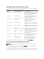
Managed Object Used in This Document
The MIB is divided into several major groups. The following table provides information about the MIB
names, name of the agent that uses each MIB and the purpose:
MIB Name Agent / Hardware Supported Purpose of the MIB
10892.mib Server Administrator Provides the information about the systems
monitored by Server Administrator
instrumentation software. This is the primary
MIB for PowerEdge systems.
dcs3fru.mib Server Administrator Provides the information about the system
Field Replaceable Unit (FRU) to SNMP
management applications.
dcstorag.mib Server Administrator Storage
Management
Provides the information about the storage
hardware components and RAID
configurations monitored by Server
Administrator.
iDRAC-SMIv1.mib iDRAC7 and iDRAC 8 Provides information about the SNMP data,
and traps, supported by the iDRAC7. This is
for SMv1.
iDRAC-SMIv2.mib iDRAC7 and iDRAC 8 Provides information about the SNMP data,
and traps, supported by the iDRAC7. This is
for SMv2.
dcs3rmt.mib Dell Remote Access controller 5
(DRAC 5)
Provides information about remote access
components monitored by the Server
Administrator Remote Access Service.
rac_host.mib Remote access out-of-band
agent
Provides information about the components
monitored by the remote access out-of-
band software agent.
DELL-RAC-MIB.txt Chassis Management Controller
(CMC)
Provides information about components
monitored by the Chassis Management
Controller for modular chassis.
DcAsfSrv.mib Baseboard Management
Controller (BMC)
Provides information about Dell server
Platform Event Traps generated by the
Baseboard Management Controller.
For further details see Release Notes for Management Information Base readme_mibs.txt.
Server Administrator Remote Access MIB
NOTE: This section contains information that is applicable only if the Server Administrator is
installed in the system.
The Server Administrator Remote Access MIB ( filename dcs3rmt.mib ) provides in-band information
about remote access hardware that may be present in your system.
The Server Administrator Remote Access MIB structures its MIB objects into groups of scalar objects or
MIB tables that provide related information. Table below describes each Server Administrator Remote
6

Access MIB group and lists the MIB group number assigned to the MIB group. The Server Administrator
Remote Access MIB groups are identified by the SNMP OID 1.3.6.1.4.1.674.10892.1.<MIB group number>
where <MIB group number> is the MIB group number assigned to the MIB group. See the relevant section
for more information about the MIB objects defined in a MIB group.
Table 1. Server Administrator Remote Access MIB Sections in This Guide
Section Topic MIB Group Numbers
19 Remote Access Group — provides information about
remote access hardware that may be present in your
system and defines variables for administrative users,
SNMP trap destinations, modem configuration for dial-up
networking, dial-in configuration, and dial-out
destinations
1700
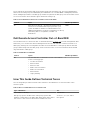
Dell Remote Access Controller Out-of-Band MIB
The Dell Remote Access Controller Out-of-Band MIB (filename dellRAC.mib) provides management data
that allows you to monitor the Chassis Management Controller. This MIB also contains information on
RAC legacy alerting. The following table describes each Dell RAC Out-of-Band group and lists the MIB
group number assigned to the MIB group. See the relevant section for more information about the MIB
objects defined in a MIB group.
Table 2. Dell RAC Out-of-Band MIB
Section Topics MIB Group Number
25 The Dell RAC Out-of-Band MIB consists of information
for the following groups:
• Product Information
• Chassis Status
• Chassis Power
• CMC Power Information
• CMC PSU Information
• Chassis Alerts
• Legacy Alerting
2
How This Guide Defines Technical Terms
The following table provides information about where to find definitions for technical terms in this
reference guide.
Table 3. Where to Find Definitions for Technical Terms
Type of Definition See
Basic SNMP vocabulary. Introduction
MIB-group-specific variable values. MIB-group-specific MIB
variables contain links to the tables that define these values in the
last section of the section in which these variables are used.
Sections 3, 5, 7, 8, 9, and 11
through 18.
7

Type of Definition See
Systems management terms, acronyms, and commonly managed
components referred to in this reference guide.
Glossary available on the Dell
Support web site at dell.com/
support/manuals.
Server Administrator-standard data types that specify variable
values in this reference guide.
Appendix A, Standard Data Type
Definitions.
Basic Terminology
It is important to have a good understanding of the key technical terms used in this guide. This guide
provides definitions for all essential terms used in describing the Server Administrator MIBs. For definitions
on all essential terms and acronyms, see the Glossary available on the Dell Support website at dell.com/
support/manuals.
Frequently Used Terms in Variable Names
The following terms are frequently used in the name of a MIB variable:
Capability refers to the actions an object can perform, or to actions that can be taken by the object. Hot-
pluggable is an example of a capability. If a card is hot-pluggable, it can be replaced while a system is
running. Capability settings refer to the capabilities of the object that the user can select from and
activate if desired. Capability settings allow users of the server administrator to predetermine how an
object behaves under specific conditions.
Settings are the conditions of a manageable object that determine what happens when a certain value is
detected in a component. For example, a user can set the upper critical threshold of a temperature probe
to 75 degrees Celsius. If the probe reaches that temperature, the setting causes an alert to be sent to the
management console. Some settings, when reached, can trigger a system shutdown or other response to
prevent damage to the system.
State refers to the condition of an object that has more than one condition. For example, an object may
be in a not ready or in an enabled state.
Status refers to the health of an object or how the object is functioning. For example, the status of a
temperature probe that is measuring acceptable temperatures would be reported as normal. When the
probe begins reading temperatures that exceed limits set by the user, it reports a critical status.
Tables
This reference guide contains two types of tables: tables that are used to organize and define variable
values and tables that define MIB objects. Readers must understand the difference between these two
types of tables.
SNMP Tables
Most of the MIB objects defined in this reference guide are organized into SNMP tables. SNMP tables
organize data into two-dimensional structural arrays. In SNMP, objects that have a relationship to other
objects are called columnar objects. Columnar objects are objects used to form lists and tables. When a
MIB group is divided into one or more discrete tables, the word table has a technical meaning. An
8

example is the section of this reference guide entitled Universal Unique Identifier (UUID). The UUID object
has a type and a value that uniquely identifies an object such as a chassis. The table defines all of the
variables that comprise the managed object UUID.
The following table is an example of an SNMP table. The table contains variables that must occur in a
definite sequence. In the example table the defined variables are UUID Chassis Index, UUID Index, UUID
Type, and UUID Value.
These objects comprise the Server Administrator definitions for the UUID.
Table 4. UUID Table
Name
uUIDTable
Object ID 1.3.6.1.4.1.674.10892.1.300.20
Description Defines the UUID table.
Syntax SEQUENCE OF UUIDTableEntry
Access Not accessible
Table 5. UUID Table Entry
Name
uUIDTableEntry
Object ID 1.3.6.1.4.1.674.10892.1.300.20.1
Description Defines the UUID table entry.
Syntax UUIDTableEntry
Access Not accessible
Index
uUIDIndex
,
uUIDchassisIndex
Table 6. UUID Chassis Index
Name
uUIDchassisIndex
Object ID 1.3.6.1.4.1.674.10892.1.300.20.1.1
Description Defines the index (one-based) of this chassis.
Syntax DellObjectRange
Access Read-only
Table 7. UUID Index
Name
uUIDIndex
Object ID 1.3.6.1.4.1.674.10892.1.300.20.1.2
Description Defines the index of the UUID in a specified chassis.
Syntax DellObjectRange
9

Access Read-only
Table 8. UUID Type
Name
uUIDType
Object ID 1.3.6.1.4.1.674.10892.1.300.20.1.3
Description Defines the type of the UUID for this chassis.
Syntax DellUUIDType
Access Read-only
Table 9. UUID Value
Name
uUIDValue
Object ID 1.3.6.1.4.1.674.10892.1.300.20.1.4
Description Defines the value of the UUID for this chassis.
Syntax Octet String (SIZE[16])
Access Read-only Read-only
Other Documents You May Need
In addition to this guide, you can access the following guides available on the Dell Support website at
dell.com/support/manuals. On the Manuals page, click Software Systems Management. Click the
appropriate product link on the right-side to access the documents.
• The Server Administrator Messages Reference Guide lists the messages that you can receive on your
systems management console or on your operating system’s event viewer. This guide explains the
text, severity, and cause of each message that the server administrator issues.
• The Server Administrator CIM Reference Guide documents the Common Information Model (CIM)
provider, an extension of the standard management object format (MOF) file. The Server-
Administrator CIM provider documents supported classes of management objects.
• The Glossary provides information on the terms used in this document.
10

2
SNMP Traps
SNMP is frequently used to monitor systems for fault conditions such as temperature violations, hard
drive failures, and so on. Management applications can monitor for these conditions by polling the
appropriate OIDs with the Get command and analyzing the returned data. This method has its drawbacks.
If it is done frequently, significant amounts of network bandwidth can be consumed. If it is done
infrequently, the response to the fault condition may not occur in a timely fashion. SNMP traps avoid
these limitations of the polling method.
An SNMP trap is an asynchronous event indicating that something significant has occurred. This is
analogous to a pager receiving an important message, except that the SNMP trap frequently contains all
the information needed to diagnose a fault.
Two drawbacks to SNMP traps are that they are sent using UDP, which is not a guaranteed delivery
mechanism, and that they are not acknowledged by the receiver.
An SNMP trap message contains the trap’s enterprise OID, the agent IP address, a generic trap ID, the
specific trap ID, a time stamp, and zero or more variable bindings (varbinds). The combination of an
enterprise OID and a specific trap ID uniquely identifies each Server Administrator-defined trap. A varbind
consists of an OID and its value and provides additional information about the trap.
In order for a management system to receive SNMP traps from a managed system, the node must be
configured to send traps to the management system. Trap destination configuration is dependent on the
operating system. When this configuration is done, a management application on the management
system can wait for traps and act on them when received.
For a list of traps supported by the Server Administrator Instrumentation Service, see Instrumentation
Traps. For information on Server Administrator Storage Management traps, see Storage Management
Alert Reference.
For a list of traps supported by the Remote Access Controller, see RAC Traps, BMC Traps and iDRAC7
Traps.
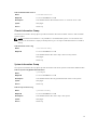
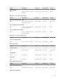
Trap Variables
This section describes the variables both on Traditional and Enhanced varbinds that are sent to the
management console to provide additional information about a trap or alert generated by some event on
your system. The trap variables presented here apply to all Instrumentation and RAC traps. Trap variables
are sent in the order listed and are reserved for use only in traps. When a varbind is created for a trap
variable, a zero is appended to the object ID (OID) to create the OID for the varbind.
The messages associated with each alertMessage varbind are available in the Message Reference Guide
and can be found by matching the alert ID in the MIB to the event ID in the Message Reference Guide.
11

Table 10. Trap Variables
Variable Name
alertSystem
Object ID 1.3.6.1.4.1.674.10892.1.5000.10.1
Description Identifies the system generating the alert.
Syntax DisplayString
Table 11. Table Index OID
Variable Name
alertTableIndexOID
Object ID 1.3.6.1.4.1.674.10892.1.5000.10.2
Description Specifies the object identifier for the index attribute in the table that
contains the object causing the alert. Uniquely identifies the object
causing the alert and can be used to correlate different alerts caused by
the same object.
Syntax
OBJECT IDENTIFIER
Table 12. Message
Variable Name
alertMessage
Object ID 1.3.6.1.4.1.674.10892.1.5000.10.3
Description Describes the alert.
Syntax DisplayString
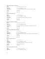
Table 13. Current Status
Variable Name
alertCurrentStatus
Object ID 1.3.6.1.4.1.674.10892.1.5000.10.4
Description Specifies the current status of the object causing the alert.
Syntax DellStatus
Table 14. Previous Status
Variable Name
alertPreviousStatus
Object ID 1.3.6.1.4.1.674.10892.1.5000.10.5
Description Specifies the previous status of the object causing the alert.
Syntax DellStatus
Table 15. Data
Variable Name
alertData
Object ID 1.3.6.1.4.1.674.10892.1.5000.10.6
Description Provides Server Administrator-defined data related to the alert.
12

Syntax Octet String
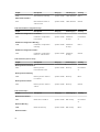
The following variables show the Enhanced varbinds:
Table 16. Message ID
Variable Name
alertMsgID
Object ID 1.3.6.1.4.1.674.10892.4.5000.10.7
Description Specifies the enhanced message ID for the object generating the alert.
Syntax DisplayString
Table 17. System FQDN
Variable Name
alertSystemFQDN
Object ID 1.3.6.1.4.1.674.10892.4.5000.10.8
Description Specifies fully qualified domain name of the system generating the alert.
Syntax DisplayString
Table 18. Service Tag
Variable Name
alertServiceTag
Object ID 1.3.6.1.4.1.674.10892.4.5000.10.9
Description Specifies the system service tag of the system generating the alert.
Syntax DisplayString
Table 19. Chassis Service Tag
Variable Name
alertChassisServiceTag
Object ID 1.3.6.1.4.1.674.10892.4.5000.10.10
Description Specifies the chassis service tag of the system generating the alert.
Syntax DisplayString
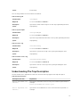
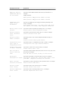
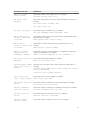
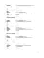
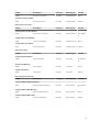
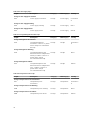
Understanding The Trap Description
The below table lists in alphabetical order each line item that may appear in the trap description.
Table 20. Trap Description
Description Line Item Explanation
Action performed was:
<Action>
Specifies the automatic server recovery action that was performed, for
example:
Action performed was: Power cycle
Action requested was:
<Action>
Specifies the user initiated host control action that was requested, for
example:
13

Description Line Item Explanation
Action requested was: Reboot, shutdown OS first
Additional details:
<Additional details
for the events>
Specifies possible additional details about the specified device, for
example:
Additional details:
Memory device: DIMM_1A Serial number: 11111111
Memory device: DIMM_1B Serial number: 22222222
<Additional power
supply status
information>
Specifies any additional power supply information pertaining to the
event, for example:
Power supply input AC is off, Power supply POK (power
OK) signal is not normal, Power supply is turned off
Battery sensor status:
<status>
Specifies the status reported by the battery sensor, for example:
Battery sensor status: Predictive failure
Chassis intrusion
state: <Intrusion
state>
Specifies the chassis intrusion state (open or closed), for example:
Chassis intrusion state: Open
Chassis location:
<Name of chassis>
Specifies the name of the chassis that generated the message, for
example:
Chassis location: Main System Chassis
Configuration error
type: <type of
configuration error>
Specifies the type of configuration error that occurred, for example:
Configuration error type: Revision mismatch
Current sensor value
(in Amps): <Reading>
Specifies the current sensor value in amps, for example:
Current sensor value: 7.853
Date and time of
action: <Date and
time>
Specifies the date and time that an automatic server recovery action was
performed, for example:
Date and time of action: Fri May 30 23:55:44 2003.
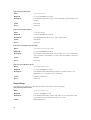
Description:
<Description of event>
Specifies the description of the event that occurred, for example:
Description: Chipset Err: Critical Event sensor, front
panel NMI / diagnostic interrupt was asserted.
Device location:
<Location in chassis>
Specifies the location of the device in the specified chassis, for example:
Device location: Mem Card A
Discrete current
state: <State>
Specifies the state of the current sensor, for example:
Discrete current state: Good
Discrete temperature
state: <State>
Specifies the state of the temperature sensor, for example:
Discrete temperature state: Good
14

Description Line Item Explanation
Discrete voltage
state: <State>
Specifies the state of the voltage sensor, for example:
Discrete voltage state: Good
Fan sensor value:
<Reading>
Specifies the fan speed in revolutions per minute (RPMs) or On/Off, for
example:
Fan sensor value (in RPM): 2600
Fan sensor value: Off
Log type: <Log type>
Specifies the type of hardware log, for example:
Log type: Embedded Server Management (ESM)
Memory device bank
location: <Bank name
in chassis>
Specifies the name of the memory bank in the system that generated
the message, for example:
Memory device bank location: Bank_1
Memory device
location: <Device name
in chassis>
Specifies the location of the memory module in the chassis, for
example:
Memory device location: DIMM_A
Number of devices
required for full
redundancy: <Number>
Specifies the number of power supply or cooling devices required to
achieve full redundancy, for example:
Number of devices required for full redundancy: 4
Peak value (in Watts):
<Reading>
Specifies the peak value in Watts, for example:
Peak value (in Watts): 125
Possible memory module
event cause: <list of
causes>
Specifies a list of possible causes for the memory module event, for
example:
Possible memory module event cause: Single bit warning
error rate exceeded
Single bit error logging disabled
Power Supply type:
<type of power supply>
Specifies the type of power supply, for example:
Power Supply type: VRM
Pre-failure state was:
<State>
Specifies the status of the previous memory message, for example:
Pre-failure state was: Failed
Previous redundancy
state was: <State>
Specifies the status of the previous redundancy message, for example:
Previous redundancy state was: Lost
Previous state was:
<State>
Specifies the previous state of the sensor, for example:
Previous state was: OK (Normal)
Processor sensor
status: <status>
Specifies the status of the processor sensor, for example:
15

Description Line Item Explanation
Processor sensor status: Configuration error
Redundancy unit:
<Redundancy location
in chassis>
Specifies the location of the redundant power supply or cooling unit in
the chassis, for example:
Redundancy unit: Fan Enclosure
SD card device type:
<Type of SD card
device>
Specifies the type of SD card device, for example:
SD card device type: Hypervisor
SD card state: <State
of SD card>
Specifies the state of the SD card, for example:
SD card state: Present, Failed
Sensor location:
<Location in chassis>
Specifies the location of the sensor in the specified chassis, for example:
Sensor location: CPU1
Temperature sensor
value (in degrees
Celsius): <Reading>
Specifies the temperature in degrees Celsius, for example:
Temperature sensor value (in degrees Celsius): 30
Voltage sensor value
(in Volts): <Reading>
Specifies the voltage sensor value in volts, for example:
Voltage sensor value: 1.693
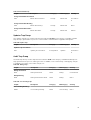
Understanding Trap Severity
Traps often contain information about values recorded by probes or sensors. Probes and sensors monitor
critical components for values such as amperage, voltage, and temperature. When an event occurs on
your system, the Server Administrator sends information about one of the following event types to the
system management console:
• Information/Informational—An event that describes the successful operation of a unit, such as a
power supply turning on or a sensor reading returning to normal.
• Warning — An event that is not necessarily significant, but may indicate a possible future problem,
such as crossing a warning threshold.
• Critical/Error — A significant event that indicates actual or imminent loss of data or loss of function,
such as crossing a failure threshold or a hardware failure.
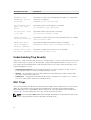
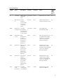
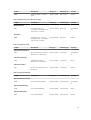
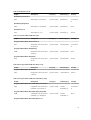
RAC Traps
This section describes the traps that are generated by the SNMP agent of the Remote Access Controller
(RAC). All of the enterprise-specific traps documented in this section belong to the MIB enterprise
identified by OID 1.3.6.1.4.1.674.10892.2 and are sent with all of the trap variables documented in the
section Traps . The trap variables are sent in the order in which they are listed.
NOTE: The PowerEdge M1000e CMC and PowerEdge VRTX CMC do not generate the traps in this
section. They generate the traps documented in the CMC Traps.
16

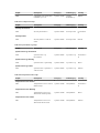
Table 21. RAC Traps
TrapID Name Description Severity Category Cause Support
ed by
RAC
Platfor
m
0 CodeStart SNMP agent is
initializing
itself
Informatio
n
Status RAC power on or reset. All
1 Authenticati
on
Failure
Request
received with
an invalid
community
name
Critical Error SNMP request with an
invalid community name.
All
1001 alertDrscTe
st TrapEvent
The RAC
generated a
test trap event
in response to
a user request
Informatio
n
Status A test SNMP trap
generated by a RAC.
All
1002 alertDrscAut
h Error
RAC
Authenticatio
n failures
during a time
period have
exceeded a
threshold
Minor Error RAC login failure caused
by authentication failure,
number of concurrent
logins exceed limit, or
permission denied.
All
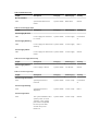
1015 alertDrscSE
L
Warning The
RAC has
detected a
new event in
the System
Event Log
with Severity:
Warning
Major Error RAC detected a new
system event log with
warning severity (detailed
log info is in drsAlert
Message varbind).
All
1016 alertDrscSE
L
Critical The
RAC has
detected a
new event in
the System
Event Log
with Severity:
Critical
Critical Error RAC detected a new
system event log with
critical severity (detailed
log info is in drsAlert
Message varbind).
All
1017 alertDrscSE
L 80
percentFull
The RAC
system event
log is 80% full
Major Status RAC detected system
event log is 80% full.
All
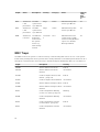
17

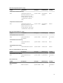
TrapID Name Description Severity Category Cause Support
ed by
RAC
Platfor
m
1018 alertDrscSE
L 90
percentFull
The RAC
system event
log is 90% full
Major Status RAC detected system
event log is 90% full.
All
1018 alertDrscSE
L 90
percentFull
The RAC
system event
log is 90% full
Major Status RAC detected system
event log is 90% full.
All
1020 alertDrscSE
L Normal
The RAC has
detected a
new event in
the System
Event Log
with Severity:
Normal
Informatio
n
Error RAC detected a new
system event log with
normal severity (detailed
log info is in drsAlert
Message varbind).
All
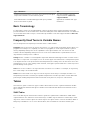
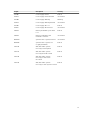
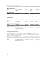
BMC Traps
The BMC monitors the system for critical events by communicating with various sensors on the system
board and by sending alerts and log events when certain parameters exceed their preset thresholds. All of
the traps documented in this section belong to the MIB enterprise identified by OID 1.3.6.1.4.1.3183.1.1.1.
TrapID Description Severity
262402 Generic Critical Fan Failure Critical
262530 Generic Critical Fan Failure
Cleared
Information
131330 Under-Voltage Problem (Lower
Critical - going low)
Critical
131458 Under-Voltage Problem Cleared Information
131841 Generic Critical Voltage Problem Critical
131840 Generic Critical Voltage Problem
Cleared
Information
65792 Under-Temperature Warning
(Lower non-critical, going low)
Warning
65920 Under-Temperature Warning
Cleared
Information
65794 Under-Temperature Problem
(Lower Critical - going low)
Critical
65922 Under-Temperature Problem
Cleared
Information
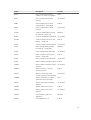
18

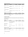
TrapID Description Severity
65799 Over-Temperature warning
(Upper non-critical, going high)
Minor
65927 Over-Temperature warning
Cleared
Information
65801 Over-Temperature Problem
(Upper Critical - going high)
Critical
65929 Over-Temperature Problem
Cleared
Information
131328 Under-Voltage Warning (Lower
Non Critical - going low)
Warning
131456 Under-Voltage Warning Cleared Information
131330 Under-Voltage Problem (Lower
Critical - going low)
Critical
131458 Under-Voltage Problem Cleared Information
131335 Over-Voltage Warning (Upper
Non Critical - going high)
Warning
131463 Over-Voltage Warning Cleared Information
131337 Over-Voltage Problem (Upper
Critical - going high)
Critical
131465 Over-Voltage Problem Cleared Information
131841 Generic Critical Voltage Problem Critical
131840 Generic Critical Voltage Problem
Cleared
Information
356096 Chassis Intrusion - Physical
Security Violation
Critical
356224 Chassis Intrusion (Physical
Security Violation) Event Cleared
Information
262400 Generic Predictive Fan Failure
(predictive failure asserted)
Minor
262528 Generic Predictive Fan Failure
Cleared
Information
262402 Generic Critical Fan Failure Critical
262530 Generic Critical Fan Failure
Cleared
Information
264962 Fan redundancy has been
degraded
Warning
264961 Fan Redundancy Lost Critical
19

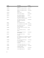
TrapID Description Severity
264960 Fan redundancy has returned to
Normal
Information
2715392 Battery Low (Predictive Failure) Warning
2715520 Battery Low (Predictive Failure)
Cleared
Information
2715393 Battery Failure Critical
2715521 Battery Failure Cleared Information
487169 CPU Thermal Trip (Over
Temperature Shutdown)
Critical
487297 CPU Thermal Trip (Over
Temperature Shutdown) Cleared
Information
487168 CPU Internal Error Critical
487296 CPU Internal Error
Cleared
Information
487173 CPU Configuration Error Critical
487301 CPU Configuration Error Cleared Information
487175 CPU Presence (Processor
Presence detected)
Information
487303 CPU Not Present (Processor Not
Present)
Critical
487170 CPU BIST (Built In Self Test)
Failure
Critical
487298 CPU BIST (Built In Self Test)
Failure Cleared
Information
487176 CPU Disabled (Processor
Disabled)
Critical
487304 CPU Enabled (Processor Enabled) Information
487178 CPU Throttle (Processor Speed
Reduced)
Warning
487306 CPU Throttle Cleared (Normal
Processor Speed)
Information
527106 Power Supply Redundancy
Degraded
Warning
527105 Power Supply Redundancy Lost Critical
527104 Power Supply Redundancy has
returned to Normal
Information
552704 Power Supply Inserted Information
552832 Power Supply Removed Warning
20
Page is loading ...
Page is loading ...
Page is loading ...
Page is loading ...
Page is loading ...
Page is loading ...
Page is loading ...
Page is loading ...
Page is loading ...
Page is loading ...
Page is loading ...
Page is loading ...
Page is loading ...
Page is loading ...
Page is loading ...
Page is loading ...
Page is loading ...
Page is loading ...
Page is loading ...
Page is loading ...
Page is loading ...
Page is loading ...
Page is loading ...
Page is loading ...
Page is loading ...
Page is loading ...
Page is loading ...
Page is loading ...
-
 1
1
-
 2
2
-
 3
3
-
 4
4
-
 5
5
-
 6
6
-
 7
7
-
 8
8
-
 9
9
-
 10
10
-
 11
11
-
 12
12
-
 13
13
-
 14
14
-
 15
15
-
 16
16
-
 17
17
-
 18
18
-
 19
19
-
 20
20
-
 21
21
-
 22
22
-
 23
23
-
 24
24
-
 25
25
-
 26
26
-
 27
27
-
 28
28
-
 29
29
-
 30
30
-
 31
31
-
 32
32
-
 33
33
-
 34
34
-
 35
35
-
 36
36
-
 37
37
-
 38
38
-
 39
39
-
 40
40
-
 41
41
-
 42
42
-
 43
43
-
 44
44
-
 45
45
-
 46
46
-
 47
47
-
 48
48


Dell OpenManage Server Administrator Version 8.0.1 Owner's manual
- Type
- Owner's manual
- This manual is also suitable for
Ask a question and I''ll find the answer in the document
Finding information in a document is now easier with AI
Related papers
-
Dell OpenManage Server Administrator Version 8.3 Owner's manual
-
-
-
-
-
Dell PowerEdge MX7000 Owner's manual
-
-
-
-