Page is loading ...

OPERATOR'S MANUAL
Liquid Propane Gas (LPG) Grill
Model CGE06ALP
NOTE TO ASSEMBLER / INSTALLER:
Leave this manual with the consumer.
NOTE TO CONSUMER:
Keep this manual for future reference.
RECORD YOUR SERIAL # __________________
(see silver CSA label on main body of grill)
Manual # P80170001A - Date:2006/01/17
Grill Information Center:
Call us first if you have any problem with this
product. We can help you with questions about
assembly and grill operation or if there are
damaged or missing parts when you unpack this
unit from the shipping box. Please call before
returning to the store.
1-800-761-5456
8am-4:30pm CST, Monday through Friday
Ÿ
Ÿ
IMPORTANT:
Ÿ
FOR YOUR SAFETY
Do not store or use gasoline or other
flammable vapors or liquids in the
vicinity of this or any appliance.
!
!
Before using this gas appliance read
all instructions and perform all gas
leak-check procedures even if the
product was pre-assembled by the
retailer or manufacturer.
Improper installation, adjustment,
alteration, service or maintenance can
cause property damage, injury or death.
Read the installation, operating and
maintenance instructions thoroughly
before installing or servicing this equip-
ment.
WARNING

2
Table of Contents
Primary Safety Warnings...........................1-3
Warranty Terms and Conditions..................2
Pre-Assembly Instructions..............................3
Part Diagrams and Lists..........................4-7
Assembly Instructions...............................8-11
Use & Care Instructions:
• Gas Safety and Leak Tests..........12-14
• Lighting Instructions................................15
• Troubleshooting.........................................16
• Cleaning and Maintenance...............17-18
• Frequently Asked Questions...........A1-A2
•
•
WARNING
!
!
Ÿ
Ÿ
Ÿ
•
•
Use your grill at least 3 feet away from
any wall or surface. Use your grill at least
3 feet away from combustible objects that
can melt or catch fire (such as vinyl or wood
siding, fences and overhangs) or sources
of ignition including pilot lights on water heaters
and live electrical appliances.
THIS GAS APPLIANCE IS DESIGNED FOR
OUTDOOR USE ONLY.
Combustion byproducts produced when using
this product contain chemicals known to
the State of California to cause cancer, birth
defects, or other reproductive harm.
LPG grill models must be used with Liquid
Propane Gas and the regulator assembly
supplied. Natural Gas models must be used
with Natural Gas only. Any attempt to convert
the grill from one fuel type to another is extremely
hazardous and will void the warranty.
Never use your gas grill in a garage, porch, shed,
breezeway or any other enclosed area.
Never obstruct the flow of ventilation air around
your gas grill housing.
Never disconnect the gas regulator or any gas
fitting while your grill is lit. A lit grill can ignite
leaking gas and cause a fire or explosion which
could result in property damage, personal injury
or death.
Keep gas regulator hose away from hot grill
surfaces and dripping grease. Avoid unnecessary
twisting of hose. Visually inspect hose prior
to each use for cuts, cracks, excessive wear
or other damage. If the hose appears damaged
do not use the gas grill. Call: 1-800-761-5456
for a authorized replacement hose.
•
Manufacturer:
Grand Hall Enterprise Co., Ltd.
9th Fl., No.298, Rueiguang Rd., Neihu,
Taipei, Taiwan (114)
Grand Hall will warrant to the ORIGINAL PURCHASER
of this gas grill that it will be free of defects in material
and workmanship for set periods below from the date of
purchase when used under normal outdoor use and
correct assembly:
Full Warranty on Grill – 1 year
(except for paint loss, rusting and ignitor battery)
Stainless Steel Parts and Tube Burners – 5 years no
rust through
Cooking Grids – 3 years no rust through
Savor Plates® – 2 years no rust through
Grand Hall will require reasonable proof of your date of
purchase. Therefore, you should send in the owner
registration card or register your grill online at
www.grandhall.com. Save your receipt in case if required
as proof of purchase.
This Limited warranty is limited to repair or replacement
of parts, at Grand Hall’s option that proved to be
defective under normal use and service.
Grand Hall may require the return of defective parts
for examination before issuing replacement parts or
repairs. If you are required to return defective parts,
transportation charges must be prepaid.
Upon examination and to Grand Hall’s satisfaction, if
the original part is proven defective Grand Hall may
approve your claim and elect to replace such parts
without charge. You are responsible for shipping
charges of such replacement parts.
This Warranty does not cover any failures or operating
difficulties due to accident, abuse, misuse, alteration,
misapplication, vandalism, improper installation,
maintenance or service, damages caused by flashback
fires or grease fires, as set out in this Operator’s Manual.
Deterioration or damage due to severe weather
conditions such as hail, hurricane, earthquakes, tsunami,
tornadoes, Acts of God or terrorism, discoloration due to
exposure to chemicals either directly or in the atmo-
sphere, is not covered by this Limited Warranty.
No returns will be accepted without prior authorization
from Grand Hall. Authorization for return may be
obtained by calling 1-800-761-5456. 8 am – 4:30 pm
CST, Monday through Friday.
Warranty Restrictions
Grand Hall Limited Warranty
•
•
This grill is safety certified for use only in the
country where purchased. Modification for use in
any other location is a safety hazard and will
void the warranty.
This warranty gives you specific legal rights, and
you may also have other rights which vary from
state to state.

3
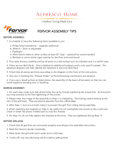
Gas Valve
Orifice
Pre-Assembly Instructions For Your Safety
Spiders and small insects can spin webs and
nest in the grill Burner Tubes during transit and
warehousing which can lead to a gas flow
obstruction resulting in a fire in and around the
Burner Tubes. This type of "FLASHBACK FIRE"
can cause serious grill damage and create an
unsafe operating condition for the user.
To reduce the chance of FLASHBACK
FIRE you must clean the Burner Tubes
as follows before intial use. Also do this at
least once a month in summer and fall or
whenever spiders are active in your area, and if
your grill has not been used for an extended
period of time.
WARNING
! !
Failure to comply with these instructions could
result in a fire or explosion that could cause
serious bodily injury, death or property damage.
METHOD 1: Bend a stiff wire or wire coat
hanger into a small hook as shown and run
the hook through the Burner Tube and inside
the Burner several times to remove debris.
METHOD 2: Use a bottle brush with a flexible
handle and run the brush through the Burner
Tube and inside the Burner several times to
remove any debris.
METHOD 3: Use an air hose to force air
through each Burner Tube. The forced air
should pass debris or obstructions through
the Burner and out the Ports.
1. Remove the screw from the rear of each Burner
using a Phillips Head Screwdriver.
2. Carefully lift each Burner up and away from the
Gas Valve Orifice.
3. Check and clean Burner/Venturi Tubes for insects
and insect nests. A clogged tube can lead to a fire
beneath the grill.
4. Refer to the figure below and perform one of
these 3 cleaning methods:
9
TO CLEAN BURNER TUBE,
INSERT HOOK HERE
Grill Information Center 1-800-761-5456
8am-4:30pm CST, Monday through Friday
Tools Required for Assembly include:
protective work gloves
protective eyewear
You will need assistance from another person to handle
the grill head and other large, heavy parts.
Open Lid of shipping carton and remove top sheet of
cardboard and / or packing materials. Lay cardboard
sheet on floor and use as a work surface to protect
floor and grill parts from scratches.
You may slice the carton front corners with a utility
knife to lay open the carton front panel. This allows
you to raise the grill head Lid and remove the
components packed inside, making it easier to lift.
Use the Hardware and Part Diagrams to ensure all
items are included and free of damage.
Do not assemble or operate the grill if it appears
damaged. If there are damaged or missing parts
when you unpack the shipping box or you have
questions during the assembly process, call the:
To expedite the assembly process follow these
general guidelines:
NOTE: This gas grill is designed to be used with two
20lb LP Gas tanks (not included) for 8 burner opera-
tion. A tank placed on the right will operate the four
right-side burners. A tank placed on the left will operate
the four left-side burners.
•
•
•
Phillips Head Screwdriver
Grill Installation Codes
The installation must conform with local codes or, in the
absence of local codes, with the National Fuel Gas Code,
ANSI Z223.1/NFPA 54, or the Natural Gas and Propane
Installation Code, CSA B149.1, as applicable, including:
1. The appliance and its individual shutoff valve must be
disconnected from the gas supply piping system
during any pressure testing of that system at test
pressures in excess of 1/2 psi (3.5 kPa).
2. The appliance must be isolated from the gas supply
piping system by closing its individual manual shutoff
valve during any pressure testing of the gas supply
piping system at test pressure equal to or less than
1/2 psi (3.5 kPa).
For safe operation ensure the Gas Valve Assembly
Orifice is inside the Burner Tube before using your
grill. See figure. If the Orifice is not inside the Burner
Tube, lighting the Burner may cause explosion
and/or fire resulting in serious bodily injury and/or
property damage.
DANGER
!
!
Leaking gas may cause a fire or
explosion which could result in property
damage, personal injury or death.
1.
2
3.
4.
IF YOU SMELL GAS:
Shut off gas to the appliance.
Extinguish any open flame.
Open lid.
If odor continues, keep away from
the appliance and immediately call
your gas supplier or your fire
department.
Foot
Burner
Burner Port

4
The following table illustrates a breakdown of the hardware pack. It highlights what parts are used in
the various stages of assembly.
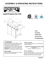
Hardware Pack Parts List for Model CGE06ALP
* Two Batteries/AA included in the Hardware Pack.
Phillips Head Screw 1/4"x1/2"
QTY. 28
Part # S112G04081
Lock Nut 3/8"
QTY. 2
Part # S372G06111
Hardware Pack Diagram for Model CGE06ALP
Spring Washer 3/8"
QTY. 2
Part # S411G06081
PART #PART DESCRIPTIONQTYPURPOSE OF PART
P06024001A Hardware Pack1For use in assembly
S112G04061
Phillips Head Screw 1/4"x3/8"4Installs Tank Holders on the Cart Frame
S112G04081Phillips Head Screw 1/4"x1/2"8Installs Casters on the Cart Frame
S112G04081
Phillips Head Screw 1/4"x1/2"8Secures Cart Bracket onto the Cart Frame
S372G06111
S411G06081
S211G06531
Lock nut 3/8"
Spring Washer 3/8"
Wheel Bolt 3/8"x5-5/16"
2
2
2
Secures 8" Wheels onto the Cart Frame
S112G03061Phillips Head Screw 3/16"x3/8"4Installs Lid Handles to Lids
S112G04081Phillips Head Screw 1/4"x1/2"12
Install Cart Handles on the Left and Right Bowl Support
Bracket
Phillips Head Screw 1/4"x3/8"
QTY. 4
Part # S112G04061
Phillips Head Screw 3/16"x3/8"
QTY. 4
Part # S112G03061
Wheel Bolt 3/8"x5-5/16"
QTY. 2
Part # S211G06531
Scale 1:2

5
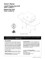
Parts Diagram for Model CGE06ALP
24
39
39
a
b
44
33
28B
28A
27
26
36
37
40
38
20
18
20
41
35
34
32
29
25
12
31
30
20
2321
19
10
16
13
43
4
22
42
11
14
7
9
8
6
5
15
17
3
1
2
45

6
Parts List for Model CGE06ALP
KEYPART DESCRIPTIONPART #QTY
1Lid, LeftP00127046A1
2Lid, RightP00128046A1
3Lid HandleP00203016B2
4Cooking GridP01612002B4
5Savor Plate®P01708018B8
6BurnerP02008023A8
7Gas Collector Box with ElectrodeP02609002B8
8Burner BracketP02216015A1
9Grease Tray Heat ShieldP06904044C2
10Wind Shield AssemblyY0480003
1
11Bowl Panel, RearP0072561EC
1
12Bowl Panel, FrontP0073861EC
1
13Bowl Panel, LeftP0072061EC
1
14Bowl Panel, RightP0072161EC
1
15Bowl Support BracketP01303015B
2
16Electric Wire SetP02615022A
1
17Lighting StickP05507031E
1
18Cart HandleP00205078B
2
19Protective PadP05518010I4
20Latch AssemblyP05517002L
8
21Hose BracketP05341002E
2
22Gas Valve/Manifold Assembly BracketP03324002H
1
23Regulator with Hose/Two Stage (LPG)P03624003A
2
24Gas Valve / Manifold Assembly, LeftY0060314
1
25Gas Valve / Manifold Assembly, RightY0060315
1
26Control Panel , UpperP02911553S
1
27Control Panel , LowerP02911561S
1
28aControl KnobP03429012J
8
28bControl Knob SeatP03415054A
8
29Electric Ignitor, 4-portP02502164C
2
30Grease TrayP02717163C
1
31Grease Receptacle P02701267C
1
32Tank HookP04005007A
2
33Cart Leg, LeftP00904004B
1
34Cart Leg, RightP00905004B
1
35Cart Frame BracketP03339001C
2
36Cart Frame P03335003C
1
37Cart SeatP04518001A
4
38Tank HolderP04008007A
2
39aWheel, 8 in.P05103014A
2
39bWheel Hub CapP05113011E
2
40Caster, 4 in., with BrakeP05120002D
2
41Cart Bottom ShelfP03340001C
1
42Savor Plate® BracketP03328015A
16
43End CapP04522001A
4
44Cart BracketP05327025A
2

7
KEYPART DESCRIPTIONPART #QTY
45Name PlateP00407010D
1
CoverP07002046B
1
Operator's ManualP80170001A
1
Hardware PackP06024001A
1
Parts List for Model CGE06ALP
To obtain the correct replacement parts for your gas grill, please refer to the part numbers in this parts
list. The following information is required to ensure you receive the correct parts:
1. Model and Serial Number (see CSA label on grill)
2. Part Number
3. Part Description
4. Quantity of parts needed
Important: Use only factory authorized parts. The use of any part that is not factory authorized can be
dangerous and will also void your product warranty. Keep this Operator's Manual for convenient referral
and for part replacement.
For the repair or replacement parts you need call our Grill Information Center at 1-800-761-5456

8
Assemble Cart
1
Assembly Instructions
2
Install Tank Holders to each side of Cart Frame.
(Tighten securely using 4 Phillips Head Screws
1/4"x3/8").
With an assistant, lift Cart out of shipping carton
and place it on the cardboard work surface.
Unfold the Cart Legs and straighten the Cart
Frame Bracket until a click sound is heard.
CAUTION: Do not stand, lean or apply pressure
to the Cart Frame Bracket once assembled.
Install Tank Holders, Casters and Wheels
Install Casters to each side Right Cart Leg.
(Tighten securely using 8 Phillips Head Screws)
Install Cart Brackets to each side Left Cart Leg
using 4 Phillips Head Screws 1/4"x1/2" and attach 8"
Wheels using 2 Wheel Bolts 3/8"x5-1/8", 2 Spring
Washers and 2 Flange nuts and tighten securely.
Phillips Head Screw 1/4"x3/8"
QTY. 4
Part # S112G04061
Lock Nut 3/8"
QTY. 2
Part # S372G06111
Wheel Bolt 3/8"x5-5/16"
QTY. 2
Part # S211G06531
Scale 1:2
Casters Installation Code
The installation shall be made with a connector that complies
with the Standard for Connectors for Movable Gas Appliances,
ANSI Z21.69-CSA6.16.
Phillips Head Screw 1/4"x1/2"
QTY. 16
Part # S112G04081
Spring Washer 3/8"
QTY. 2
Part # S411G06081
L
R
L
R

9
4
Install Grill Bowl
With an assistant, lift and position Grill Bowl onto the Cart.
Lock 4 Latches on Grill Bowl and Cart.
3
Install Lid Handles to Left and Right Lid.
(Tighten securely using 4 Phillips Head Screws 3/16"x3/8")
Install Cart Handles to each Bowl Support Bracket.
(Tighten securely using 12 Phillips Head Screws1/4"x1/2")
Install Handles
Phillips Head Screw 1/4"x1/2"
QTY. 12
Part # S112G04081
Phillips Head Screw 3/16"x3/8"
QTY. 4
Part # S112G03061
Latch

10
5
Lift and slide the Grease Receptacle out from the Grease Tray
Bracket, from the rear of the Cart.
Unscrew the Wing Bolts on each side of the Grease Tray and
remove the Grease Tray from Bottom Bowl panel.
Reinstall Grease Tray and Grease Receptacle
Attach the Grease Tray to the Bottom Bowl panel using the Wing
bolts and tighten securely.
The Grease Tray is required to be present and centered for your
safety.
Slide the Grease Receptacle over Grease Tray Bracket.
Note: Preassembled Grease Tray and Grease Receptacle
CART REAR VIEW
Wing Bolt
Grease Receptacle

11
6
Install Ignitor Batteries
Unscrew Ignitor Cap from Control Panel.
Place supplied AA battery into the Ignitor
Slot with positive pole facing you.
Position the Cap and Spring over the AA
battery and tighten onto Control Panel.
Repeat to install the other AA battery
into the Ignitor Slot.
WARNING
!
Failure to read and follow the Use and Care
Instructions could result in a fire or explosion
that could cause serious bodily injury, death or
property damage.
!
Install Cooking Components
Place the Savor Plates on lower ledge
above Burners.
Place Cooking Grids on bowl ledge.
With the assistance of another person,
perform this Electrode Check before
proceeding.
This test will ensure that the Spark Electrode
Tips are properly positioned so your grill lights
easily and properly.
Be sure all Control Knobs are set to
"OFF" and open the Grill Lids.
Have your assistant stand behind to the
right of the grill and look toward the front
of the grill bowl. Never put your face
inside the Grill Head.
Press the Ignitor Cap. You should hear
a "clicking" sound. Your assistant should
see a blue spark within each Gas
Collector Box. If a spark is present the
Electrode Tips are properly positioned.
If no spark is seen, the Spark Gap
needs to be adjusted as follows:
•
•
•
Using an adjustable wrench, loosen the
Inside Nut until the Gas Collector Box
can be turned upward.
If the gap between the Spark Electrode
Tip and Receiver is more than 3/16"
use long nose pliers to gently squeeze
the Gas Collector Box to narrow gap.
Return the Gas Collector Box to its
original position, secure the Inside Nut
and try the Electrode Check again. If no
"clicking" sound is heard:
AA Battery is installed backwards.
Electric wires may be loose. Remove
the AA Battery and inspect the Ignitor
Junction Box found behind the Control
Panel and reconnect any loose wires.
8
7
Final Grill Assembly Step
When you have finished assembling your
grill be sure that all screws are tightened
for safe operation of your grill.
®
-
-
Call the Grill Information Center if you have any problem with this product. We can help you with
questions about assembly and grill operation or if there are damaged or missing parts when you unpack
this unit from the shipping box. Please call before returning this product.
GRILL INFORMATION CENTER
Call 8am to 4:30pm CST 1-800-761-5456 Monday through Friday
Spark Electrode Tip
Spark Gap
Spark Receiver
Gas Collector Box
Inside Nut
Spring
+ -
AA Battery
Ignitor Cap
Ignitor Slot
Cooking Grids
Savor Plate
®

12
USE AND CARE INSTRUCTIONS
Keep fire extinguisher readily accessible. In the
event of a oil/grease fire, do not attempt to extin-
guish with water. Use type B extinguisher or
smother with dirt, sand or baking soda.
Keep your grill covered during freezing rain or
snow. Sleet and snow can block the regulator vent
hole resulting in improper and potentially dangero-
us regulator pressure.
Use your grill on a level, stable surface in an
area clear of combustible materials.
Do not leave grill unattended when in use.
Do not move the appliance when in use.
Cover your grill when not in use.
Allow the grill to cool before moving or storing.
Do not use your grill as a heater.
This grill is not intended to be installed in or on
recreational vehicles and/or boats.
WARNING
!!
Do not store a spare LP-Gas tank under or near
this appliance.
Never fill the tank beyond 80 percent full; and
If the information in "(a)" and "(b)" is not followed
exactly, a fire causing death or serious injury may
occur.
A.
B.
C.
LP Gas grill models are designed for use with two
standard 20 lb. Liquid Propane Gas (LP Gas) tanks,
not included with grill. Never connect your gas grill to
an LP Gas tank that exceeds this capacity. A tank of
approximately 12 inches in diameter by 18-1/2 inches
high is the maximum size LP Gas tank to use. You
must use an "OPD" gas tank which offers a listed
Overfill Prevention Device. This safety feature
prevents tank from being overfilled which can cause
malfunction of LP Gas tank, regulator and/or grill.
The LP Gas tank must be constructed and marked
in accordance with the Specifications for LP-Gas
Cylinders of the U.S. Department of Transportation
(D.O.T.) or the National Standard of Canada, CAN/
CSA-B339, Cylinders, Spheres and Tubes for
Transportation of Dangerous Goods; and Commis-
sion, as applicable.
The LP Gas tank must have a shutoff valve,
terminating in an LP Gas supply tank valve outlet,
that is compatible with a Type 1 tank connection
device. The LP Gas tank must also have a safety
relief device that has a direct connection with the
vapor space of the tank.
The tank supply system must be arranged for
vapor withdrawal.
The LP Gas tank used must have a collar
to protect the tank valve.
Never connect an unregulated LP gas tank to your
gas grill. The gas regulator assembly supplied with
your gas grill is adjusted to have an outlet pres-
sure of 11" water column (W.C.) for connection to
an LP gas tank. Only use the regulator and hose
assembly supplied with your gas grill. Replacement
regulators and hose assemblies must be those
specified by the Manufacturer.
Have your LP Gas dealer check the release valve
after every filling to ensure it remains free of defects.
Always keep LP Gas tank in upright position.
Do not subject the LP Gas tank to excessive heat.
Never store an LP Gas tank indoors. If you store
your gas grill in the garage always disconnect the
LP Gas tank first and store it safely outside.
LP Gas tanks must be stored outdoors in a well-
ventilated area and out of the reach of children.
Disconnected LP Gas tanks must not be stored in
a building, garage or any other enclosed area.
The regulator and hose assembly can be seen
after opening the doors (if applicable) and must be
inspected before each use of the grill. If there is
excessive abrasion or wear or if the hose is cut, it
must be replaced prior to using the grill again.
Never light your gas grill with the lid closed or
before checking to ensure the burner tubes are fully
seated over the gas valve orifices.
Never allow children to operate your grill. Do not
allow children or pets to play near your grill.
Use of alcohol or drugs may impair the ability to
assemble and operate the appliance.
CORRECT LP GAS TANK USE
WARNING
! !
•
Use your grill outdoors, at least 3 feet away
from any wall or surface. Use your grill at
least 3 feet away from combustible objects
that can melt or catch fire (such as vinyl or
wood siding, fences and overhangs) or
sources of ignition including pilot lights on
water heaters and live electrical appliances.
Never use your gas grill in a garage, porch,
shed, breezeway or any other enclosed area.
Never obstruct the flow of ventilation air around
your gas grill housing.
•
•

13
USE AND CARE INSTRUCTIONS
NOTE about LP Gas Tank Exchange Programs
Ÿ
How to Leak Test your LP Gas Tank
For your safety:
LP Gas Model only:
Secure two 20lb LP Gas Tanks to Gas Grill
CAUTION: When the appliance is not in use the gas
must be turned off at the tanks.
Cylinders Installation Code
The handling, storage, and transporation of all sizes of gas
cylinders must be in accordance with ANSI/NFPA 58,
Storage and Handling of liquid Petroleum Gases, or the CSA
B149.1, Natural Gas and Propane Installation Code.
Turn your LP Gas Tank Valves clockwise to
the closed or OFF positon.
Hang your gas tanks on the top Tank Hooks.
The ring foot of the gas tanks will rest on the
Tank Holder.
Many retailers that sell grills offer you the option of
replacing your empty LP Gas tank through an exchange
service. Use only those reputable exchange companies
that inspect, precision fill, test and certify their tanks.
Exchange your tank only for an OPD safety feature-
equipped tank as described in the LP Gas tank section
of this manual.
Always keep new and exchanged LP Gas tanks in an
upright position during use, transit or storage.
Leak test new and exchange LP Gas tanks BEFORE
connecting one to your grill.
Ÿ
Ÿ
All leak tests must be repeated each time your LP Gas
tank is exchanged of refilled.
When checking for gas leaks do not smoke.
Do not use an open flame to check for gas leaks.
Your grill must be leak tested outdoors in a well-
ventilated area, away from ignition sources such as
gas fired or electrical appliances. During the leak test,
keep your grill away from open flames or sparks.
Do not use household cleaning agents. Damage to
gas assembly components can result.
Ÿ
Ÿ
Ÿ
Ÿ
Ÿ
If growing bubbles appear do not use or move
the LP Gas tank. Contact an LP Gas Supplier
or your fire department!
WARNING
! !
Before using this gas appliance read all
instructions and perform all gas leak-check
procedures even if the product was
pre-assembled by the retailer or manufacturer.
WARNING
! !
Use a clean paintbrush and a 50/50 mild soap and
water solution.
Brush soapy solution onto LP Gas tank in the areas
indicated by the arrows. See diagram.
If growing bubbles appear do not use or move the
LP Gas tank. Call an LP Gas Supplier or your Fire
Department.
Turn all Burner Valves to the OFF position.
Inspect the valve connection port and regulator
assembly for damage or debris. Remove any
debris. Never use damaged or plugged equip-
ment.
Connect the regulator assembly to the tank
valve and HAND TIGHTEN nut clockwise to a
full stop. DO NOT use a wrench to tighten
because it could damage the Quick Coupling
Nut and result in a hazardous condition.
Open the tank valve fully (counterclockwise) and
use a soapy water solution to check all
connections for leaks before attempting to light
"Checking for LP Gas Leaks".
If a leak is found, turn the tank valve off and
do not use your grill until the leak is repaired.
LP Gas Model only:
Connect Regulator with Hose to your LPG Tanks
your grill. See
Type 1 connection per
ANSI Z21.58b-2002
Quick
Coupling Nut

14
USE AND CARE INSTRUCTIONS
Check all connections for LP Gas Leaks
Never test for leaks with a flame. Prior to first use,
at the beginning of each season, or every time
your LP Gas tank is changed, you must check for
gas leaks. Follow these three steps:
Make a soap solution by mixing one part liquid
detergent and one part water.
Turn the grill Control Knobs to the full OFF
position, then turn the gas ON at source.
Apply the soap solution to all gas connections
indicated by the arrows. See diagram. If
bubbles appear in the soap solution the
connections are not properly sealed. Check
each fitting and tighten or repair as necessary.
CAUTION: Always open both left and right Lids
as shown before lighting your grill.
If you have a gas leak that cannot be repaired by
tightening, turn off the gas at the source, disconnect
fuel line from your grill and call 1-800-761-5456
or
your gas supplier for repair assistance.
Never disconnect the gas regulator or any gas fitting
while your grill is lit. A lit grill can ignite leaking gas
and cause a fire or explosion which could result in
property damage, personal injury or death.
WARNING
! !
Disconnecting A Liquid Propane Gas (LPG)
Tank From Your Grill
Make sure the Burner Valves and LP Gas tank valve
are off. (Turn clockwise to close.)
Detach the hose and regulator assembly from the
LP Gas tank valve by turning the Quick Coupling
Nut counterclockwise.
Gas Valve / Manifold Assembly
LP Gas Tank
Two Stage Regulator
with Hose (LPG)
Lock Casters while
your grill is in use

15
USE AND CARE INSTRUCTIONS
Grill Lighting Instructions
Lighting Stick and follow steps 1 through 6 of the Grill
Lighting Instructions. Then, light the match and place
Lighting Stick through the Lighting Hole on the right side
of the grill as shown below. Turn the Control Knob
nearest the open tank to the HIGH setting to release gas.
The Burner should light immediately.
Never lean over the grill cooking area while lighting
your gas grill. Keep your face and body a safe
distance (at least 18 inches) from the Lighting Hole
or Burners when lighting your grill by match.
WARNING
!
!
Manually Lighting Your Grill By Paper Match
NOTE: This gas grill is designed to be used with two
20lb LP Gas tanks (not included) for 8 burner operation.
A tank placed on the right will operate the four right-side
burners. A tank placed on the left will operate the four
left-side burners.
Immediately press the right-side Electric Ignitor for
3-4 seconds to light the Burner.
If ignition does not occur in 5 seconds, turn the
burner Control Knob(s) and gas source OFF and
conduct a leak test of ALL gas connections and
gas sources as explained in the Use and Care
section of this manual. If no leaks are detected,
wait 5 minutes for any gas to clear and repeat
the lighting procedure.
After one Burner is lit, turn the tank valve SLOWLY one
more 1/4 of a turn for 1/2 of one complete turn.
Once one Burner is lit, the adjacent Burner can be lit
by turning its Control Knob to HIGH.
To light the four left-side burners repeat step 7 and 8
then press the left-side Electric Ignitor.
10.
11.
12.
13.
9.
6.
Before each use, check all hoses for cracks, nicks,
cuts, burns or abrasions. If a hose is damaged in
any way, do not use your grill before replacing the
hose with an authorized part from the Parts List. Also
make sure all gas supply connections are securely
tightened.
For optimum performance this grill should be used
only when outdoor temperatures are 60 degrees or
above.
Familiarize yourself with the safety and Use and Care
instructions in this manual. Do not smoke while
lighting grill or checking gas supply connections.
Be sure each LP Gas tank is filled and lock Casters
to prevent movement during grill operation.
Open the left and right Lids before lighting the grill.
Check that the end of each Burner Tube is properly
located over each Valve Orifice.
1.
5.
4.
3.
2.
Failure to replace a faulty hose, secure gas supply
connections or to open the Lid before proceeding
to the Lighting Procedures could result in a fire or
explosion that could cause serious bodily injury,
death, or property damage.
!
WARNING
!
Set all Control Knobs to OFF and open the right-side
tank valve SLOWLY 1/4 of a turn.
To light the fourth right-side burners, push and turn
the fourth Control Knob from the right to HIGH. This is
considered the middle right Control Knob.
8.
7.
To light your gas grill by match, insert a match into the
Burner Control Knobs on Control Panel
Burner Control Knobs on Control Panel
Left 4 Burners are controlled
by left LP Gas tank
Right 4 Burners are controlled
by right LP Gas tank
PRESS
OFF
HIGH
The fourth middle Control Knobs
Lighting Hole
Match
Lighting Stick
Open LP Gas tank

16
USE AND CARE INSTRUCTIONS
Troubleshooting
WARNING
Turn gas off at source and turn Control Knobs to
OFF. Wait at least five minutes for gas to clear,
then retry.
If your grill still fails to light, check gas supply
and connections.
Repeat lighting procedure. If your grill still fails
to operate, turn the gas off at source, turn the
Control Knobs to OFF, then check the following:
If the grill fails to light :
1.
2.
3.
Misalignment of Burner Tubes over Orifices
Correction: Reposition Burner Tubes over Orifices.
Obstruction in gas line
Correction: Remove fuel line from grill. Do not
smoke! Open gas supply for one second to clear
any obstruction from fuel line. Close off gas supply
at source and reconnect fuel line to grill.
Plugged Orifice
Correction: Remove the screw from the rear of
each Burner using a Phillips Head Screwdriver.
Remove the Orifice from gas valve and gently
clear any obstruction with a fine wire. Then
reinstall all Orifices, Burners, Screw and cooking
components.
If an obstruction is suspected in Gas Valves or
Manifold, call the Grill Information Center.
Obstruction in Burner Tubes
Correction: Follow the Burner Tube cleaning
procedure on page 18 of this Operator's Manual.
Misalignment of Ignitor on Burner
Correction: Check for proper position of the
Electrode Tip as shown in step 7 page 11. The
gap between the Spark Electrode Tip and Spark
Receiver should be approximately 3/16". Adjust
if necessary. With the gas supply closed and all
Control Knobs set to OFF press the Electric
Ignitor cap and check for the presence of a spark
at the Electrode.
Disconnected Electric Wires
Correction: Inspect the Ignitor Junction Box found
behind the Control Panel. Connect loose Electric
wires to Junction Box and try to light the grill.
Weak AA battery
Correction: Unscrew the Ignitor Cap and replace
the battery.
If the grill still does not light you may need to
purge air from the gas line or reset the
regulator excess gas flow device. Note: This
procedure should be done every time a new
LP Gas tank is connected to your grill.
To purge air from your gas line and/or reset
the regulator excess gas flow device:
Turn Control Knobs to the OFF position.
Turn off the gas at the tank valve.
Disconnect regulator from LP Gas tank.
Let unit stand 5 minutes to allow air to purge.
Reconnect regulator to the LP Gas tank.
Open the Grill Lids.
Turn tank valve on SLOWLY 1/4 of a turn.
Push and turn the middle Control Knob farthest
from open tank to HIGH.
Press Electric Ignitor for 3-4 seconds to light
the burners.
Keep grill area clear and free from combustible
materials, gasoline and other flammable vapors
and liquids.
Do not obstruct the flow of air for combustion
and ventilation.
Keep the ventilation openings of the tank enclosure
cabinet free and clear of debris.
Visually check burner flames occasionally to
ensure proper flame pattern as shown below.
Failure to comply with these instructions may
result in a hazardous situation which, if not
avoided, may result in injury.
•
•
•
•
CAUTION
!
!
WARNING
!
Should a FLASHBACK fire occur in or around
the Burner Tubes, follow the instructions below.
Failure to comply with these instructions could
result in a fire or explosion that could cause
serious bodily injury, death, or property damage.
!
Shut off gas supply to the gas grill.
Turn the Control Knobs to OFF position.
Open the Grill Lid.
Put out any flame with a Class B fire
extinguisher.
Once the grill has cooled down, clean
the Burner Tubes and Burners according
to the cleaning instructions in this
Operator's Manual.
GRILL INFORMATION CENTER
Call 8am to 4:30pm CST
1-800-761-5456
Monday through Friday
•
•
•
•
•
MAGNIFIED VIEW OF
BURNER FLAME
THROUGH LIGHTING
HOLE

17
Fig. 1
Proper care and maintenance will keep your grill in top
operating condition and prolong its life. Follow these
cleaning procedures on a timely basis and your grill will
stay clean and operate with minimum effort.
CAUTION: Be sure your grill is OFF and cool before cleaning.
Cleaning The Cooking Grids
Before initial use, and periodically, wash your Cooking
Grids in a mild soap and warm water solution. You
can use a wash cloth or vegetable brush to clean your
Cooking Grids.
Cleaning The Savor Plates
®
Periodically you should wash the Savor Plates
®
in a
soap and warm water solution. Use a vegetable brush
to remove stubborn burnt-on cooking residue. Dry the
Savor Plates
®
thoroughly before you reinstall them
into the cooking bowl.
Cleaning The Grease Tray and Receptacle
To reduce the chance of fire, the Grease Draining Tray
and Grease Receptacle (some models) should be
visually inspected before each grill use. Remove any
grease and wash Grease Tray and Receptacle with a
mild soap and warm water solution.
Cleaning the Inside of the Grill Lid
Grease can have a tendency to build up on the inside
of the Grill Lid and could drip onto deck or patio when
the lid is opened. Visually inspect the inside of the
Grill Lid before each grill use. Remove any grease
and wash with a mild soap and warm water solution.
Annual Cleaning of The Grill Interior
Burning-off excess food after every cookout will keep it
ready for instant use. However,at least every 3 months
you must give the entire grill a thorough cleaning to
minimize your risk of grease fire and keep the grill in
top shape. Follow these steps:
Turn all Burner Valves to the full OFF position.
Turn the LP gas tank valve to the full OFF position.
Disconnect the regulator from the gas tank. Inspect the
hose with regulator assembly for cracking, cuts or any
other damage, and replace as neccessary. Refer to the
Parts List in this Operator's Manual.
Remove and clean the Savor Plates
®
, Cooking Grids
and Grill Burners.
Cover each Gas Valve Orifice with aluminum foil.
Brush the inside and bottom of the grill with a fiber
pad or nylon brush and wash with a mild soap and
warm water solution. Rinse thoroughly and let dry.
Remove aluminum foil from Orifices and check each
Orifice for obstruction.
Check each Spark Electrode, adjusting as needed.
The space between the Spark Electrode Tip and
Spark Receiver should be approximately 3/16".
Replace the Burners and adjust the Gas
Collector Box. The edge of the collector box should
be overlapping the Burner Port.
Replace Savor Plates
®
and Cooking Grids.
Reconnect the gas source and observe the Burner
flame for correct operation.
Cleaning Exterior Surfaces:
Before initial use, and periodically thereafter, we
suggest you wash your grill using a mild soap and
warm water solution. You can use a wash cloth or
sponge for this process. Do not use a stiff wire or
brass brush. These will scratch stainless steel and
chip painted surfaces (varies by model) during the
cleaning process.
CLEANING AND MAINTENANCE
1.
2.
3.
4.
5.
6.
7.
8.
9.
Cleaning Exterior Stainless Steel Surfaces:
Weathering and extreme heat can cause exterior
stainless steel surfaces to turn tan in color.
Machine oils used in the manufacturing process
of stainless steel can also cause this tanning
color. After removing any protective PVC film from
the Control Panel, use a Stainless Steel Cleaner to
polish the stainless steel surfaces of your grill.
Never use abrasive cleaners or scrubbers because
they will scratch and damage your grill. Follow
these steps for the best results.
Turn the LP Gas tank valve (clockwise) to the full
OFF position. Disconnect the regulator and hose
assembly from LP Gas tank. Cover exposed gas
fitting with aluminum foil.
Remove dirt or grease using a soft cloth and
polish stainless surfaces. Wipe with a soft cloth.
Remove aluminum foil from exposed gas fitting
and allow grill to air dry before attaching the
regulator and hose to your LP Gas tank.
11.
10.
1.
2.
3.
1.
2.
3.
4.
5.
6.
Transporting or Storing your grill:
Fig. 2
Lock grill Casters.
Remove LP Gas tank and Grease Tray from your
grill. Place Grease Tray on Lower Grease Tray
Bracket. See Fig.1.
Loosen 4 Latches on Grill Bowl and Cart. With an
assistant, lift and position Grill Bowl on a cardboard
surface.
Fold the Cart Legs onto Cart Frame. See Fig.1.
With an assistant, lift and position Grill Bowl onto
the folded Cart. See Fig.1.
Lock 4 Latches on Grill Bowl and Cart. See Fig.2.
Be sure grill is secured tightly and covered when
being transported.

18
Figure 1
CLEANING THE BURNER TUBES AND BURNER PORTS
Turn all Burner Valves to the full OFF position.
Turn the LP Gas tank valve to the full OFF position.
Detach the LP Gas regulator assembly from your
gas grill.
Remove the screw from the rear of each Burner
using a Phillips Head Screwdriver.
Carefully lift each Burner up and away from the
Gas Valve Orifice.
Check and clean burner/venturi tubes for insects
and insect nests. A clogged tube can lead to a fire
beneath the grill.
Refer to Figure 1 and perform one of these
three cleaning methods:
Regardless of which Burner cleaning procedure you
use, we recommend you also complete the following
steps to help prolong Burner life.
1. Use a fiber pad or nylon brush to clean the entire
outer surface of each Burner until free of food
residue and dirt.
2. Clean any clogged ports with a stiff wire, such as
an open paper clip.
3. Inspect each Burner for damage (cracks or holes)
and if such damage is found, order and install a new
Burner. After installation, checkto ensure that the
Gas Valve Orifices are correctly placed inside the
ends of the Burner Tubes. Also check the position of
your Spark Electrode.
WARNING
!!
For safe operation ensure the Gas Valve
Assembly Orifice is inside the Burner Tube before
using your grill. See figure. If the Orifice is not
inside the Burner Tube, lighting the Burner may
cause explosion and/or fire resulting in serious
bodliy injury and/or property damage.
METHOD 1: Bend a stiff wire or wire coat
hanger into a small hook as shown and
run the hook through the Burner Tube and
inside the Burner several times to remove
debris.
METHOD 2: Use a bottle brush with a
flexible handle and run the brush through
the Burner Tube and inside the Burner
several times to remove any debris.
METHOD 3: Use an air hose to force air
through each Burner Tube. The forced air
should pass debris or obstructions through
the Burner and out the Ports.
TO CLEAN BURNER TUBE,
INSERT HOOK HERE
9
1.
2.
3.
4.
5.
6.
7.
8.
To reduce the chance of FLASHBACK FIRE you must
clean the Burner Tubes as follows at least once a
month in summer and fall or whenever spiders are
active in your area, and if your grill has not been used
for an extended period of time.
Remove the Cooking Grids, Savor Plates
®
and
Grease Trays from your grill.
Burner Port
BurnerFoot
Gas Valve
Orifice

19
A-1
Question:
No, your gas grill is manufactured to exact specifications
and is certified for LPG (Liquid Propane Gas) or NG
(Natural Gas) only. For your safety, a conversion kit is not
available for this model, nor will we sell or otherwise
provide parts or information to be used to convert this
grill. Any attempt to convert this grill is dangerous and
will void your warranty.
Question:
Are the serial and model numbers of my grill listed
somewhere for reference?
Answer:
The serial and model numbers are listed on a silver CSA
label placed on the grill. Depending on the grill model
the silver CSA label will be located on the left or right
side bowl panel underneath the side shelf, underneath
the right side of the control panel, outside left or right of
control panel or on the back of the grill cabinet.
Question:
My grill will not light properly. Why?
Answer:
Always light the main Burner farthest from the fuel
source first. This will draw gas across the manifold
helping prevent air pockets which obstruct gas flow and
prevent proper grill lighting. Also try this procedure:
1. Turn gas off at source and turn Control Knobs OFF.
Wait at least 5 minutes for gas to clear, then retry.
2. If your grill still fails to light, check gas supply and
connections.
3. Repeat lighting procedure.
If your grill still fails to operate, turn the gas off at
source, turn the Control Knobs to OFF and refer to the
Troubleshooting Section for more tips, or call the Grill
Information Center.
FREQUENTLY ASKED QUESTIONS (FAQ'S)
Can I convert my grill from one fuel type to another in
other words from LPG to NG or vice versa?
Answer:
Question:
Sometimes I hear a humming sound coming from my
regulator. What causes this? And - My grill has a low
flame and sometimes will not light. Why?
Answer:
The humming sound is gas flowing through the regulator.
A low volume of sound is normal and will not interfere
with the operation of your grill. Loud or excessive regulator
humming and/or low flow and intermittent lighting may
be caused by the regulator's excess gas flow device.
Opening the tank valve all the way or too quickly is what
triggers the regulator's safety device to restrict gas flow,
preventing excess gas flow to your grill. Lighting the main
Burner farthest from the fuel source every time will help
eliminate air pockets in the manifold. Note: This
procedure should be done every time a new LP Gas tank
is connected to your grill.
Turn all Control Knobs to the OFF position.
Turn off the LP Gas tank at the tank valve.
Disconnect regulator from LP Gas tank.
Let unit stand for 5 minutes.
Reconnect regulator to the LP Gas tank.
Open grill Lid (or on select models, the Side Burner
Lid if you are lighting the Side Burner).
Turn the tank valve slowly ¼ of one turn.
Light middle main Burner farthest from fuel source.
Turn the tank valve slowly one more ¼ of one turn
for ½ of one complete turn.
Continue to light Burners moving towards the tank.
Do not turn tank valve more than ½ of one turn.
Question:
Where do I use my grill for safer operation and better
performance?
Answer:
Strong winds and low temperatures can affect the
heating and performance of your gas grill so
factor in these elements when positioning your
grill outdoors for cooking.
Use your grill at least 3 feet away from any wall or
surface.
Use your grill at least 3 feet away from
combustible objects that can melt or catch fire
(such as vinyl or wood siding, fences and
overhangs) or sources of ignition including pilot
lights on water heaters and live electrical
appliances.
Never use your gas grill in a garage, porch, shed,
breezeway or any other enclosed area.
Never obstruct the flow of ventilation air around
your gas grill housing.
Question:
If my ignitor or battery is not working how can I light
my grill manually? And - Why would I need the silver
lighting stick that hangs from the side of my grill?
Answer:
If your ignition fails to work or your battery needs
replacing, you can light your grill through the Lighting
Hole on the side of the grill bowl using the Manual
Lighting Stick that hangs from the side of your grill. The
Lighting Stick is designed to hold a paper match and
allows you to safely insert a match through the Lighting
Hole without getting close to the Burner. Never remove
the Cooking Grids or Savor Plates
®
and attempt to light
the grill from above. To light your gas grill manually,
insert a paper match into the Manual Lighting Stick and
follow steps 1 through 6 of the Basic Lighting
Procedures. Then, light the match and place it through
the Lighting Hole on the right side of the grill (location
of hole varies by grill model). Turn the nearest main
Burner Control Knob to the High setting to release gas.
The Burner should light immediately.

20A-2
Question:
The Regulator and Hose supplied with my gas grill
does not fit the older LP Gas tank I’ve used for
years. Why not?
Answer:
The U.S. Government regulates gas appliances and
LP Gas tanks. When regulations are changed the LP
Gas tank fittings are altered to insure compliance. If
your LP Gas tank does not fit the Regulator and Hose
supplied with your new grill, the tank is outdated and
must be replaced. Note: Effective April 1, 2002 all LP
Gas tanks sold must include an “OPD” Overfill
Prevention Device. The OPD tanks are identified by
their triangular-shaped valve wheel. This internal
device prevents the LP Gas tank from being overfilled.
Tanks without an OPD valve can not be refilled.
Question:
What causes grill parts to rust and what affect does
it have on my grill?
Answer:
Rusting is a natural oxidation process and may
appear on cast-iron and steel parts. Rust will not
affect the short term performance of your grill.
To slow the rusting process on steel Cooking Grids
(select models) we recommend greasing the
Cooking Grids before and after each cookout. Use a
brush to apply a thin layer of cooking oil or vegetable
shortening onto each Cooking Grid. We do not
suggest spray type oils unless they are specified for
high-temperature cooking. Be sure to coat the entire
cooking surface including edges and any areas with
chipped porcelain.
Question:
Which is a better cooking surface to grill on;
porcelain coated steel / cast-iron cooking grids or
stainless steel grids?
Answer:
They all have their advantages. For traditional grilling
and searing meats, cast-iron or steel grids offer
better heat conductivity. To protect against the natural
rusting process, steel or cast-iron cooking grids offer
a porcelain finish which requires routine
maintenance to keep the grids well seasoned.
Stainless steel is popular with those who prefer less
maintenance.
A new innovative solution is available on select
models called Stainless Clad Therma-Core
®
. This
Cooking Grid combines a heat conducting steel core
with an easy-to-clean stainless outer shell.
Question:
Some stainless steel grills specify 304 grade
construction while others do not mention a grade at
all? What is the difference?
Answer:
All stainless grades are not created equal. The 304
grade, also called 18-8 stainless steel, is prized for its
excellent resistance to rust and corrosion and good
performance at high temperatures, which makes it ideal
for grill construction.
304 grade stainless steel is by far the most popular
stainless steel and contains 18-20% chromium and
8-10% nickel, making it non-magnetic.
Some stainless steel grills are constructed of Type 430
stainless steel which contains 16-18% chromium but
generally less than 1% nickel. It is magnetic with less
corrosion and rust resistance and designed for limited
temperature use. Beware of stainless steel grills that
offer no claim of grade because what looks shiny on the
sales floor could become a problem on your patio.
How can you tell if a product is made of 304 grade
stainless? Take the simple magnet test. If a magnet
sticks to the stainless steel it is 430 grade. If a magnet
does not stick you can trust its 304 grade quality.
F
R
E
Q
U
E
N
T
L
Y
A
S
K
E
D
Q
U
E
S
T
I
O
N
S
(
F
A
Q
'
S
)
You may also review FAQ’s, Troubleshooting and
Care & Maintenance Tips online at
www.grandhall.com.
/