Page is loading ...

Safety Precautions
This Product should be used according to the specifications, functions and
precautions for use as described in this document. Using this Product in other
ways may result in a loss of safe operation.
1. Introduction
In order to obtain the highest possible performance from your Linear Gage
Counter and use it safely for an extended period of time, be sure to read this
document prior to installation, setup, and operation. In addition, observe the
following precautions.
Conformity to EC directives
This unit conforms to the following EC directives:
Standerd:EN61326:1997+A1+A2+A3:1998
Immunity test requirement :Annex A
Emission limit :Class B
* When you use a commercial power supply unit, establish an appropriate
one-to-one connection with a cabling length of 30m or less between the two
pieces of equipment. Moreover, please avoid any outdoor wiring.
Precautions for Use
● Neither remove the cover nor disassemble this unit. Otherwise
you may be subject to electric shock or the unit may have a risk
of causing breakage or fire as the result of short-circuiting due to
metallic powders entered in the inside of the unit.
● Warning labels are located on the top surface of the main unit.
● This is a precision instrument. Handle this unit with your utmost
care so as not to impact or apply an excessive force to any part
of this unit.
● Use this unit in a place where the ambient temperature is within
the range of 0 to 40
C and subject to minimum variation without
causing condensation.
● Avoid using this unit in the following environments :
- Where this unit may be subject to cutting chips, machining oil,
or significant vibration.
-
Where this unit may be exposed to direct sunlight.
- Near from equipment which uses high voltage/large current.
2. Warranty
The Linear Gage Counter MTIEH542-072A has been manufactured under
rigorous Mitutoyo quality control. Should it malfunction due to the workmanship or
transportation, etc. within one year from the date of original purchase, it will be
repaired free of charge according to the description of the warranty card. Contact
your dealer or the nearest Mitutoyo sales office for more information.
3. Overview
The EH Counter is a mount-on-panel type counter conforming to DIN
size(144x72mm), which greatly facilitates the incorporation into a system. It has
incorporated diverse output functions including RS232C, USB, tolerance judgment
or BCD, and analog outputs, providing various control capabilities.
Major functions
Key function Presetting, Peak measurement, Tolerance limit
setting, and BANK-switching type tolerance judgment
Tolerance function 3/5-step tolerance limits(2-BANK)
Output function Tolerance output/BCD output (Parameter selection)
RS232C/USB/Digimatic output (Parameter
selection)
Input function Preset, Hold, BANK switching, and Peak switching
Following four models are provided depending on the gage to be connected:
Model Applicable gage Features
EH-102P
EH-101P
LGB, LGF, LGK,
LGH etc.
Providing a high resolution down to
0.1µm and high-speed response of
1.5m/s(with LGF)
EH-102D LGD, ID, SD, etc. Provided with the ABS function,
eliminating comparison with a standard
each time when the power is turned on.
EH-102Z LGF-Z, etc. Provided with the origin function which
gives a high-speed response and
reducing troubles in comparing with a
standard each time when the power is
turned on.
EH-102S LGH Providing an ultra-high resolution
display of 0.001µm
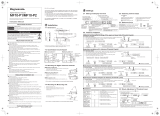
4. Appearance
5. Setup
5.1 Panel Mounting Method
1) Drilling mounting holes on the panel
2) Mounting the panel
The main body of the counter is put from the front side of the panel after the fixing
bracket of the counter is detached once, and the counter is fixed from the back of
panel with the fixing bracket. Adjust the number of supplied washers according to
the thickness of the panel to use.
Panel thickness(mm) 1.0 to 1.3 1.4 to 1.7 1.8 to 2.5 2.5 to 3.2
Number of washers 0 1 2 3
MTIEH542-072A User Manual
This shows how to
install the AC adapter.
Panel thickness allowing it to be mounted:
1.0 to 3.2mm
(1) BANK indicator
(2) Total judgment indicator
(3) UNIT indicator
(4) A-ch display
(5) B-ch display
(6) Peak indicator
(7) Gage input connector
(8) RS_LINK connector
(also used for Digimatic output)
(9) USB connector
(10) RS-232C connector
(11) I/O connector
(12) DC jack
(13) Power SW
(14) Cable clamp
WARNING
Front view (common to 2-axis models)
Front view (common to 1-axis models)
P101-HEP201-HE
EH-102Z
EH-102D
EH-102S
Side view (common to all models)
(1)
(2)
(3)
(4)
(5)
(2)
(3)
(4)
(
8
)
(9)
(10)
(11)
(12)
(13)
(
7
)
(
14
)
(6)
(6)
(
8
)
(9)
(10)
(11)
(12)
(13)
(
7
)
(
14
)

5.2 Attaching the Stand and Rubber Foot
1) Rubber foot
When you place this unit flat on a desk, attach four pieces of rubber feet under the
bottom surface of the main unit case.
Ru bber
foot
Note) This unit can not be assembled into the panel after these rubber feet are
attached.
2) Stand
Attaching (with six pieces of washers) the supplied stand to this unit in the same
way as the panel, you can use the counter main body as it is inclined.
5.3 Making Connections
1) Do not omit making any of the following connections:
● Connect a Mitutoyo Linear Gage to the INPUT connector.
● Supply power into the DC IN connector (Use a Mitutoyo-specified AC adapter
or the supplied DC plug).
● Connect the grounding wire to the grounding terminal.
2) Make the following connections as required:
● Connect a cable (D-sub 9-pin cross-type cable) to the RS-232C connector. This
cable must be prepared by the user Refer to "10. RS232C/USB/Digimatic
Output Function").
● Connect the dedicated cable to the RS-LINK connector. Always use a
Mitutoyo-specified cable (Refer to "17. Optional Accessories").
● Connect the dedicated cable to the I/O connector. This cable must be prepared
by the user (Refer to “11. I/O Connector Terminal Function”).
3) Internal wiring of the DC plug
For using an external power supply, solder power cable wires to the terminals of
the supplied plug as shown in the figure below.
+V
-V
Note the following when using this unit:
● Use only a power source for this unit that is rated to 12 to 24V and
control output current more than 1A. Never use this power source with
other electric equipment that runs at a high voltage and/or large
current.
● Do not let the power supply cable and gage cable run through a cable
duct together with other power line.
● Be sure to use shielded wires for the I/O cable and limit the cable
length to 3m or less.
● Never omit grounding this unit.
● Each connection cable must be secured to the main body of this unit,
etc.
● Used a grounded 3-P AC outlet for the AC adapter.
6. Setting Parameters
Used to set the counting direction and minimum reading, etc. of the counter
Hereinafter [2-axis model] will be followed by the description regarding only the
functions and operations of the 2-axis models.
6.1 How to Set Parameters
tuptuo/yalpsid gnidnopserroC noitarepo yeK
1 Turns the unit power on. The counter enters the stand-by state.
2 Press the [A_ZERO] ([ZERO]/1-axis
model)key while holding down the
[P.SET] key to change to the
parameter mode.
The parameter 00 (PNo.00) will be
displayed.
Parameter
Number
Set value
3 Press [P.SET] to advance the
parameter number by one.
If [P.SET] is pressed four times
(EH-P/Z/S):
4 [2-axis model] [Setting the
measurement mode]
Press [A_ZERO] to set the required
number.
Example: Inter-axis calculation between A
and B = 1.
For detail refer to 8 Measurement Mode.
5 Press [P.SET] to advance the
parameter number by one.
6 (For each axis) [Resolution
setting]
Repeatedly press [P.SET] until the
display as in the right appears. Set
the resolution suitable for the gage
to be used.
Setting of INPUT A (EH-P/Z/S)
Set value
Parameter
Number
INPUT
Number
7 [2-axis model]
Press [P.SET] to advance to the
setting of INPUT B. [2-axis model].
Press [A_ZERO] to Modify the
setting value.
Setting of INPUT B
Set value
Parameter
Number
INPUT
Number
8 Press [P.SET] to advance the
parameter number by one.
9 Press [A_ZERO] while holding
down [P.SET].
The counter enters the stand-by state.
Note
●
In order to use the origin function with your EH-Z, set Parameter 5(PNo.5)
to one(1).
6.2 Reference: Detail of the Measurement Mode Selections
[2-axis model]
The 2-axis counter for the MTIEH-542-072A has four internal counters (CEL1-4). In
addition, it has incorporated six input circuits (UNITA-F) corresponding to your
measurement application so that various measurement displays can appear
by changing the connection between UNIT and SEL with the input selector.
This assignment of connection is specified in terms of measurement mode.
Internal block diagram
RS232C/
USB/SDP
(Parameter
selection)
(1)Input UNIT
UNIT
A
A-axis counter
BCD/Tolerance
output
(Parameter
selection)
Total
judgment
A
nalog output
UNIT C
Difference/
Sum calculation
UNIT B
B-axis counter
UNIT D
A-axis speed
UNIT E
B-axis speed
UNIT F
Memory function
(3)Output
UNIT
(4)Input
selector
(5)Output
selector
CEL1
Origin/Tole
rance peak
BANK1
CEL2
Origin/Tole
rance peak
CEL3
Origin/Toler
ance peak
CEL4
Origin/Toler
ance peak
BANK2
A
-axis
B-axis
(2)Display
UNIT
(1)Input : Supports UNIT A to UNIT F, which can be selected according to your
application.
UNIT A/B: Performs a counting measurement for either A axis or B axis.
UNIT C: Performs a real-time difference/sum calculation between A axis
and B axis.
UNIT D/E: Performs a simplified moving speed measurement for A-axis or
B-axis.
UNIT F: Memorizes the display value.
(This is active even during the power OFF.)
(2)Display: Possible to select which to display BANK1 or BANK2.
BANK1(CEL1-2),BANK2(CEL3-4)
Each CEL can be used independently for origin detection, peak
detection, and tolerance judgment.
(3)Output: It is possible to select the output I/F to be used by the corresponding
parameter.
(4)Input selector: It is possible to connect the input UNIT to an optional internal
counter.
(5)Output selector: Outputs the displayed value of BANK1 or BANK2.
W
as
h
ers
Screw
NOTE
Stand (supplied accessory)
This is not
necessary if the
mount-on-pane
l method is
Fixing bracket
Rubberfoot(standardaccessory)
Stand (standard accessory)
About 10°
Fixing bracket

Measurement mode selections (Parameter No.6)
2KNAB 1KNAB
Parameter
value
Measurement mode CEL1 CEL2 CEL3 CEL4
0 2-coordinate measurement
UNITA
(Count of A)
UNITB
(Count of B)
UNITA
(Count of A)
UNITB
(Count of B)
1 Differential measurement
UNITC
(A±B)
UNITA
(Count of A)
UNITC
(A±B)
UNITB
(Count of B)
2
*2
Dual-program measurement
UNITA
(Count of A)
UNITA
(Count of A)
UNITB
(Count of B)
UNITB
(Count of B)
3 Measurement with memory
UNITA
(Count of A)
UNITF
(Memory)
UNITB
(Count of B)
UNITF
(Memory)
4 Speed measurement
UNITA
(Count of A)
UNITD
(Speed of A)
UNITB
(Count of B)
UNITE
(Speed of B)
5
*3
Optional 1-axis measurement
UNITA
(Count of A)
6
*3
Optional 2-axis measurement
UNITA
(Count of A)
UNITB
(Count of B)
7
*3
Optional 4-axis measurement
UNITA
(Count of A)
UNITB
(Count of B)
UNITC
(A±B)
UNITA
(Count of A)
*1 When BANK1 is displayed with the setting specified to 1 (differential measurement),
A-ch (upper row) shows the A±B calculation value, while B-ch (lower row) shows the
INPUTA counting value. Otherwise when BANK2 is displayed, A-ch (upper row) shows
the A±B calculation value, while B-ch (lower row) shows the INPUTB counting value.
*2 Settings at shipment is O (2-coordinate measurement mode)
*3 For detail refer to "8. Measurement Mode Functions".
6.3 List of Parameters
No.
Parameter name
Axis
specification
setting
Initial
value
00 Parameter mode selection 0:Parameter
multiplier
1:CEL-specific
parameter
2:Constant setting 0
3:Parameter save 4:Parameter load
01 User parameter clear *1 0:Disable
(One-shot)
1:Initialization
(restores the
initial value.)
0
02 Key protection
Prevents operation mistake.
0:Normal 1:Key input
disable
0
05 Origin function selections
(only for EH-Z)
*2 0:Disable 1:Enable 0
06 Measurement mode selection
(only for 2-axis models)
*12 0:2-coordinate 1:Calculation 2:Simultaneous
display
0
01* 3:Memory 4:Speed
(excluding EH-D)
5:Optional 1ch
6:Optional 2 ch 7:Optional 4 ch
07 Start-up mode (only for EH-P/D/S) 0:"----" display 1:0.000 0
Start-up mode
(When origin function is enabled for EF-Z)
0:”----“ display 1:Wait for origin
point to be detected.
0
09 mm/E unit system display selection 0:mm 1:E 5/ 100,000
reading
2:E 1/ 10,000
reading
0
(E=1 / 25.4mm) initialization disable 3:mm *7
10 Gage/scale output signal pitch
(only for EH-S)
For2 axes
*12
0:20um 1:4um 2:0.25um(LGH) 2
11 Counting direction selection
(when the spindle is retracted)
For2 axes 0:+count 1:-count 0
12 0:10um 1:5um 2:1um 2
Gage resolution setting
(only for EH-P/Z)
3:0.5um 4:0.1um 5:0.1(LGH)
Gage type setting (only for EH-D)
*4
0:INC 1:ABS 1
0:10um 1:5um 2:1um
3:0.5um 4:0.1um 5:0.05um 6
Gage resolution setting (only forEH-S)
When PNo10=0: 0 to 4 *9
When PNo10=1: 2 to 5
When PNo10=2: 4 to 8
For2 axes
*12
6:0.01um 7:0.005um 8:0.001um
13 µ decimal point display 0:Disable 1:Enable 0
14 C-axis calculation setting
[Only for 2-axis models]
0:A+B 1:A-B 0
15 Smoothing (averaging)
(only for EH-P/Z/S)
0:None 1:16 times 2:32 times 0
16 Peak vale presetting *11 0:Disable 1:Enable 0
18 Speed sampling cycle
(only for EH-P/Z/S)
0:10ms 1:50ms 2:100ms 0
19 SDP input WAIT (EH-D) *6 0:0 WAIT 1:100ms WAIT 2:200ms WAIT 0
20 Tolerance / BCD output mode
switching
*12 0:3-step tolerance 1:5-step tolerance 2:BCD output 0
21 BCD output logic selection *8
*12
0:DATA [L]
(Sign H)
1:DATA [H]
(Sign L)
0
24 RS232 / Digimatic selection *5 0:RS232C 1:USB 2: SDP 0
5* etar duaB 52 0:4800 1:9600 2:19200 1
5* ytiraP 62 0:None 1:Odd 2:Even 2
5* tib ataD 72 0:7bit 1:8bit 0
28 RS232C output trigger selection *5 0:RS232command
(normal)
1:RS232Ccommand
(Csynchronizing)
2:
HOLD trigger OUT 0
30 Analog output range 0:1999 to -1999 1:19990 to -19990 2:199900 to
-199900
0
31 Origin detecting direction
(only for EH-Z)
For2 axes 0:+count 1:-count 0
32 Origin re-detection (only for EH-Z) *3 0:Disable 1:Enable 0
33 Origin initialization (only for EH-Z) 0:Disable 1:On initialization On one-shot 0
*1 Clearing this parameter allows the unit to restore the unit conditions at shipment
*2 A type of gauge, like LGF-Z, which has the specific internal origin, will generate signals the moment when the
spindle is moved and a reference point on it passes over the internal origin. Based on this mechanism the
EH-Z will restore the preset position.
*3 Usually the origin point detection is performed only when the unit power is turned on. However, the unit
operation will enter t
he wait state for origin re-detection at the rise of the HOLD signal where the origin
re-detection function has been activated by the corresponding parameter. If the HOLD signal is inputted again
after the origin is re-detected, the origin re-detection function will be canceled except during cancellation of
any error.
*4 An ABS-type gauge continuously memorizes the origin even when the unit power is OFF. Make up this setting
according to the type of gage to be used.
Activate the INC mode when you want to make the displays on a
gage like ID and SD and on the counter consistent.
*5 The operation is valid after the unit power is turned on.
*6 The EH-D may cause an error rarely when it is connected with a special type of gage. If this is the case, set
PNo.19 to either 1 or 2.
*7 When a 7-inch gage is connected as to read 1/10,000 (only for EH-D).
*8 In relation to output of +000000, the [ ] shows the voltage of the numerical data l
ine and ( ) shows the voltage
of the sign.
*9 The setting range may be limited depending on the setting of PNo=10. Example) If PNo.10=0, a range of 0 to
4 is permitted for PNo.12.
*10 EH-D model can not perform speed measurement. Use EH-P/Z/S.
*11 During the peak mode the preset value is established based on the peak value.
*12 Modifying the parameter will clear preset values and tolerance values having been set.
6.4 How to Set CEL-specific Parameters
Set the LSD blank out and constant calculation individually for each CEL.
Key operation Corresponding display/output
1 With [P.SET]+
[A_ZERO] change to the
parameter mode, and
set as PNo.00=1.
2 Press [P.SET].
Set
Value
Paramete
r
Number
CEL
Number
htiw tes sretemarap rehto rof ylralimiS 3
[A_ZERO] and [P.SET].
4 Press [A_ZERO] while
holding down [P.SET].
The counter enters the stand-by state.
CEL-specific parameters
No. Parameter name Initial
value
40 Individual CEL display
selections
CEL 0:UNIT A
(Count of A)
1:UNIT B
(Count of B)
2:UNIT C
(calculation)
*1 [2-axis model] *2 1-4 3:UNIT D
(Speed of A)
4:UNIT E
Count of B)
5:UNIT F
(Memory)
-
41 Calculation with a
constant
CEL 0:None 1:x1/2 2:x2 0
1-4 3:x10 4:Optional setting *3
42 LSD blank out CEL
1-4
0:All-digit display 1:LSD blank out 0
*1 When PNo.6 = 5, 6 , or 7, you can assign an optional UNIT to each CEL. Modifying this paramete
r
will clear preset values and tolerance values having been set.
*2 For EH-D the setting of PNo.40=3, 4 (speed) is invalid.
*3 For the method of setting constants, refer to Section 9.
6.5 Save and Load of Parameter File [2-axis models]
The parameter data you have set can be saved into or loaded from a text
file through RS232C. In order to communicate with a PC, you must prepare
appropriate communication software at the PC side. Use HyperTerminal
(standard software supplied with Windows), etc.
1) Saving parameters [2-axis model]
Key operation Corresponding display/output
1 With [P.SET]+
[A_ZERO] change to
the parameter mode
and set as PNo.00=3,
then press [P.SET].
A display like the following appears for
one second while the data is outputted to
the PC.
2 After transmission The counter enters the stand-by state.
*Transmission conditions are fixed to 9600bps, 7-bit data, even parity, and 2 stop
bits.
*Connect the counter to the PC one-to-one (LINK connection not permitted).
Output example
CQ01,**EH-S [200]**:00
CQ01,P02___=[0],0-1:02
CQ01,P05___=[0],0-1:03
CQ01,P10_A_=[0],0-1:36
CQ01,P10_B_=[0],0-1:37
CQ01,P40_1_=[0],0-4:42
CQ02,P40_2_=[0],0-4:43
CQ03,P40_3_=[0],0-4:44
CQ04,P40_4_=[0],0-4:45
CQ01,*prameter END*:FF
CQ01,P02___=[0],0-1:02
Internal
data
P
arame
t
er
number
V
a
l
ue se
t
b
y
parameter
R
ange o
f
parameter
setting value
Example of
axis-specific
parameters
Example of
CEL-specific
parameters
*Only the value set by the parameter can be modified within the range of parameter
setting value.
2) Loading parameters [2-axis model]
Key operation Corresponding display/output
1
Set as PNo.00=4, then
press [P.SET].
The display will look like the following while
waiting for input.
2
Send the parameter file
from the PC.
If it is successfully (normally) received, the
display will look like the following.
3. Press [P.SET].
3 Press [P.SET]. The counter enters the stand-by state.

7. Operation method
7.1 Turning the Power On
Key operation Corresponding display/output
1 Turn the power on.
Enters the counting stand-by state.
2 Press [SEL].
The counter display is restored to (for
EH-P/D). *1
)Z-HE rof( etats tiaw noitceted nigirO
All decimal points will flash.
3 Push-in the spindle to
make it pass over the
origin.
The counter display is restored to
(*2 only for EH-P/D).
Note
*1 For EH-D, pressing [SEL] can display the absolute position of the gage.
*2 For origin detection, make the spindle surely pass over the origin. If
the spindle shakes near the origin, the detection may not be sure.
7.2 Zero Setting
Use the [A/B_ZERO] key to achieve zero-setting.
Key operation Corresponding display/output
1
Activate the normal
measurement with the
peak mode in advance.
MAX, MIN: Off (when count value is 1.000)
2 [A_ZERO] or [B_ZERO]
([ZERO]/1-axis model)
This clears also the peak value, resulting that
MAX = MIN = current value, and TIR = 0.
* When an error occurs, press the [A/B_ZERO] or [SEL] key to cancel the error.
7.3 Switching to the Objective Display BANK [2-axis model]
The EH counter has incorporated two BANK counter sets, either of which
can be used by switching to with the key or external signal.
Key operation Corresponding display/output
1
Press [MODE] while
holding down [P.SET] to
switch to the BANK for
display.
The selected BANK will be identified by the
BANK indicator.
Contents of display
BANK1 BANK2
A-ch (upper row) CH1
(CEL1)
CH3
(CEL3)
B-ch (lower row) CH2
(CEL2)
CH4
(CEL4)
7.4 Switching Objective Axis of Operation [2-axis model] and
Canceling Error
For presetting, peak mode, or tolerance setting operation, specify A-ch
(upper row) or B-ch (lower row) in advance with the SEL key. When an error
occurs, positively cancel the error.
Key operation Corresponding display/output
1
Press the
[SEL] key.
Display of the operated row will be flashing. Each time [SEL]
is pressed, the flashing operation alternates between A-ch
and B-ch.
A: Upper row display
CH number (CEL number)
Unit number
B: Lower row display
CH number (CEL number)
Unit number
* In the above example, UNITA (counting of A) and UNITB (counting of B) are
assigned to A:
Upper row display and B: Lower row display respectively. CH01 and
CH02 are the gage channel numbers for RS232C.
* When the calculation with constant has been set, the LED display for the least
significant digit will be ”=” as with B-ch.
Note
While any error on EH-D is being canceled, all decimal points will be
flashing for approximately 8 seconds.
7.5 Setting Peak Mode Selections
Select the objective value of display in this mode from among Maximum value
(MAX), Minimum value (MIN), and [MAX - MIN] (TIR).
Key operation Corresponding display/output
1 Select either A-ch or B-ch with [SEL]. [2-axis model]
Current value: Current position of contact point
MAX:Maximum value after clearing peak
value
MIN:Minimum value after clearing peak value
2
Switch the
display value for
the peak mode.
TIR:MAX-MIN
7.6 Clearing Peak Value
In the peak mode the user can clear the current peak value.
Key operation Corresponding display/output
1 Select either A-ch or B-ch with [SEL]. (2-axis model)
2
Select either MAX, MIN,
or TIR display with
[MODE].
The peak indicator will turn on.
3
Clear the peak value with
[A_ZERO] or [B_ZERO].
MAX=MIN=Current value
TIR=0
* If the same UNIT is assigned to more than 1 CEL, it is possible to clear the peak
value of all the same UNIT by clearing the peak value of one of them.
7.7 Presetting
Set the origin to an optional value. This is possible by means of external PA/PB
signal.
1) Setting the Preset Value
Key operation Corresponding display/output
1
Select either A-ch or B-ch
with [SEL] (2-axis model).
While [SEL] is being held down, the currently
selected axis will be flashing.
2
Use [P.SET] to enter the
setting mode.
The previous preset value will be displayed.
(where the previous value is 10.000)
L1 of the LMIT indicator and decimal point are
flashing.
3
Method of Entering Setting
Values
Move to the digit to enter
the value with [MODE].
Use [A/B_ZERO] to enter
the setting value.
For only the most significant digit set the
polarity sign.
The MSD will change as follows :
0>9>-0>-9>0.
4
Use [P.SET] to exit the
setting mode.
After the setting is completed, the counter
display will be restored to.
* Cancel, if necessary, the entered value by [SEL] and return to the counter
display.
7.8 Setting Tolerance Values
1)
Setting 3-step tolerance limits (3-step tolerance zone selection)
With the tolerance limits being set as S1 and S4 below, the 3-step tolerance
judgment will take effect as follows (S2 and S3 are not used).
GO/NG indicator I/O output
Measured value < S1 Amber indicator turns on. L1
S1 ≤ Measured value ≤ S4 Green indicator turns on. L3
S4 < Measured value Red indicator turns on. L5
Key operation Corresponding display/output
1
Select A: Upper row or B:
Lower row by [SEL].
The upper or lower row display will be
flashing (2-axis model).
2
Use [LMIT] to display the
item to be set.
S1: Amber indicator turns on.
S2: Red indicator turns on.
3 Set the value.
Use the [MODE] + [A/B_ZERO] key to set
the numeric value.
4 Accept with [LMIT]. Set S1 and S4 in this order.
* An error will occur except the setting of S1 ≤ S4. If an error occurs, press [SEL]
to redo from S1.

2) Setting 5-step tolerance limits (5-step tolerance zone
selection)
User can select one of the 5-step tolerance zones by means of switching the
parameter.
With the tolerance limits being set as S1 to S4 below, the 5-step tolerance
judgment will take effect as shown in the table below.
GO/NG indicator I/O output
Measured value < S1 Amber indicator turns on. L1
S1 ≤ Measured value < S2 Amber indicator flashes. L2
S2 ≤ Measured value ≤ S3 Amber indicator turns on. L3
S3 < Measured value ≤ S4 Red indicator flashes. L4
S4 < Measured value Red indicator turns on. L5
Key operation Corresponding display/output
1
Select A: Upper row or B:
Lower row by [SEL].
The upper or lower row display will be
flashing.
2
Use [LMIT] to display the
item to be set.
S1: Amber indicator turns on.
S2: Amber indicator flashes.
S3: Red indicator flashes.
S4: Red indicator turns on
3 Set the numeric value.
Use the [MODE] + [A/B_ZERO] key to set
the numeric value.
4 Accept with [LMIT]. Set S1, S2, S3, and S4 in this order.
*Similarly for 3-step tolerance limits, set in the order of S1, S2, S3, and S4.
An error will occur except the setting of S1<S2<S3<S4 or S1=S2=S3=S4.
8. Measurement Mode Functions [2-axis model]
The following describes measurement examples using diverse range of
measurement functions provided in the EH counter.
8.1 2-Coordinate Display
This is to display two coordinates with a set of two counters called BANK1 and
BANK2.
It is possible to set origin and tolerance limit for each BANK.
Parameter setting PNo.6=0
2KNAB 1KNAB
A: Upper row display CH1 UNIT_A
(A-axis counting)
CH3 UNIT_A
(A-axis counting)
B: Lower row display CH2 UNIT_B
(B-axis counting)
CH4 UNIT_B
(B-axis counting)
Operation Press [MODE] while holding down [P.SET] to switch to the
BANK for display.
8.2 Differential/Sum Calculation Display
Displays A ± B calculation for thickness/step measurement.
Parameter setting
PNo.6=1
PNo.14= 0:A+B 1:A-B
2KNAB 1KNAB
A: Upper row display CH1 UNIT_C (A±B) CH3 UNIT_C (A±B)
B: Lower row display CH2 UNIT_A
(A-axis counting)
CH4 UNIT_B
(B-axis counting)
*For A and B use the gages providing an identical resolution.
8.3 Simultaneous Display of Current Value and Peak Value
Displays the current value and peak value of one gage at a time.
Possible to switch over INPUTA and INPUTB by means of switching BANK.
Parameter setting
PNo.6=2
2KNAB 1KNAB
A: Upper row display CH1 UNIT_A
(A-axis counting)
CH3 UNIT_B
(B-axis counting)
B: Lower row display CH2 UNIT_A
(A-axis counting)
CH4 UNIT_B
(B-axis counting)
*Perform origin point setting independently for A: Upper row display and B: Lower
row display
8.4 Simplified Speed Display (only for EH-P/Z/S)
Gives a simplified display of moving speed of the gage spindle.
In addition to the current speed, it is possible to display the maximum speed as
MAX in the peak mode.
Parameter setting
PNo.6=4
PNo.18 (sampling interval)
0:10ms/1:50ms/2:100ms
2KNAB 1KNAB
A: Upper row display CH1 UNIT_A
(A-axis counting)
CH3 UNIT_B
(B-axis counting)
B: Lower row display CH2 UNIT_D
(A-axis speed)
CH4 UNIT_E
(B-axis speed)
*In mm/sec display, display of the lower 1 to 3 digits might be fixed depends on the
sampling time.
*Peak MIN gives the maximum speed in the reverse direction.
*This is not suitable for feedback control.
8.5 Memorizing Display Value [2-axis model]
A: Upper display value can be memorized in B: Lower row. It is possible to
recall the maximum and minimum values of the past data in addition to the
latest data that has been saved in the memory. Contents of the memory remain
valid even when the power is turned OFF.
Parameter setting PNo.6=3
2KNAB 1KNAB
A: Upper row display CH1 UNIT_A
(A-axis counting)
CH3 UNIT_B
(B-axis counting)
B: Lower row display CH2 UNIT_F (memory CH4 UNIT_F (memory
Memory save Memorizes with [B_ZERO].
Recall of
maximum/minimum
Recall of maximum/minimum value of the data memorized
during the operation of peak mode setting.
Memory clear
Specify B: Lower row with [SEL] and press [P.SET].
Value stored in memory(NOM, MAX, MIN)=A: Upper display
value
* The memory unit is common to both BANK1 and BANK2. For these
BANKs, use the gages that have an identical resolution.
* Possible to externally control with B_HOLD signals.
9. How to Set Optional Constant Values
Use any constant you have set with parameter No.41 = 4.
Key operation Corresponding display/output
1
Parameter PNo.00=“2”
2
Press [P.SET]. The previously set value will be displayed in
Upper row, and the CEL number will be
displayed in Lower row.
3 Set the numeric value with
the[MODE][A/B_ZERO]key
in the same way as for
presetting.
Range of setting values ±9.99999
4 Press [A_ZERO] while
holding down [P.SET].
The next CEL setting value will be
displayed. The counter display will be
restored when the setting is completed up to
CEL4.
Note
● During use of this function the accuracy certificate is invalid.
10.
RS232C/USB/Digimatic Output Function
Use the corresponding parameter to select one from the RS232C/USB/Digimatic
output.
10.1 RS_232C Communication Function
1) List of commands
Command format Corresponding output Operation
GA**CRLF G#**,+01234.567CRLF
*1
Outputs "Display value".
CN**CRLF *5 CH**CRLF Switches the display to
"Current value".
CX**CRLF *5 CH**CRLF Switches the display to
"Maximum value".
CM**CRLF *5 CH**CRLF Switches the display to
"Minimum value".
CW**CRLF *5 CH**CRLF Switches to the "TIR" display.
CR**CRLF CH**CRLF Zero-setting
CL**CRLF CH**CRLF Clears peak value.
CP**,+01234567CRLF *2 CH**CRLF Inputs preset value.
CD**,+01234567CRLF *3 CH**CRLF Inputs tolerance limit S1.
CE**,+01234567CRLF CH**CRLF Inputs tolerance limit S2.
CF**,+01234567CRLF CH**CRLF Inputs tolerance limit S3.
CG**,+01234567CRLF CH**CRLF Inputs tolerance limit S4.
CS**CRLF CH**CRLF Canceling error
CK**CRLF CH**,%CRLF HOLD status *4
*1 [**] denotes a gage channel number between 01 and 99("00" means all
channels).Channels 01 thru Channel 04 are assigned to CEL1 to CEL4,
respectively.
[#] denotes the type of data N : Current value, X : Maximum value, M : Minimum
value, W : TIR .CRLF means CR carriage return plus LF line feed). Output
during error will be "CH**,Error$$CRLF" $$ is the error code. Refer to "12. Error
Displays").
*2 For presetting and tolerance limit setting, enter each value consisting of a sign
and 8 digits of numeric value without a decimal point.

*3 Perform the tolerance limit setting in the order of CD and CG for the case of
3-step tolerance judgment, and in the order of CD, CE, CF, and CG for the case
of 5-step tolerance judgment. When the order of tolerance limits is different from
the correct order, or if the data according to the set number of steps is different
from those which are actually sent out, an error will be outputted. If this is the
case, redo the settings from the beginning of the CD command.
*4 A response output of CK command ("%") shows the HOLD status.
% 0 : Normal state, 1 : HOLD status
All counters which are LINK-connected by the CK command at the time of
PNo28=1 (CH synchronization) enter the HOLD state. This HOLD state will be
canceled when you attempt data read with the GA command. The CK command
is valid only with CH1.
*5 If the peak mode is switched using an RS-232C command, peak values cannot
be backed up in memory.
Note 1. After you have received a response output corresponding to the
previous command, send the next command. When there is no
response from your command,
clear the communication buffer, then
send the command again after one second or more.
Note 2. The RS communication function will be suspended during key
operation e.g. setting parameters, preset values, or tolerance limits).
It automatically resumes the command and data output operation when
the gage is recovered to such a condition that the counting is possible.
Note 3. For canceling the counting-standby state, use
CS00CRLF(specification of all channels).
2) Connectors and cables
- Receptacle specification : D-sub 9-pin (male), inch screw specification
- Applicable plug specification : D-sub 9-pin (female), inch screw specification
- Example of commercial cable :
For DOS/V : KRS-403XF1K (1.5m), manufactured by SANWA SUPPLY.
3) Pin assignment / Communication specifications
(conforming to EIA RS232C)
1
5
9
6
Pin
No.
Signal
name
Input/
output
Description
2 RXD IN Received data
3 TXD OUT Sent data
4 DTR OUT
Data Terminal
Ready
5 GND Ground (GND)
6 DSR IN Data Set Ready
7 RTS OUT
Transmission
request
8 CTS IN Clear to Send
1,
9-15
NC
Connection
impossible
Home position DTE (Data Terminal Equipment). Use a
cross-type cable.
Communication
method
Half-duplex, non-procedural mode
Data transfer rate 4800, 9600, 19200 bps
Bit configuration Start bit: 1
Data bits: (7,8) ASCII, upper-case characters
Number of parity bits: None, even, odd
Number of stop bits: 2
Communication
conditions setting
Use the parameters. Refer to "6. Setting
Parameters".
4) Example of cable connection (D-sub 9-pin cross-type cable
specification)
Counter PC side
Pin No. Pin No.
1 1
2 2
3 3
4 4
5 5
6 6
7 7
8 8
9
9
10.2 RS_LINK Function
Chain-linking more than 2 counter units as one connected to another with a
single cable makes it possible to control maximum 10 counter units by the
RS-232C interface of the first counter.
1) Connection method
Connect between IN and OUT of the RS-LINK connectors as shown below :
IN
OUT
First counter
RS LINK
IN
OUT
IN
OUT
RS LINK connection cable
MAX10m
Max. 10 units
RS-232C
RS LINK RS LINK
Last counter
Note 1. Do not connect anything at the IN side of the LINK connector of the first
counter and at the OUT side of the last counter.
Note 2. Channel number of each gage will be automatically assigned to 01, 02,
and 03 in this order from the first counter during the initial setting after
the power is tuned on.
Note 3. The maximum total cable length permitted for the entire system is 10m.
Note 4. Configuring such a system that more than ten counter units are included
and/or the total cable length is longer than 10m, consult Mitutoyo.
2) RS_LINK connection cable
Refer to the appropriate paragraph in "17. Optional Accessories".
3) Precautions for start-up
- Power ON : Either turn on the power of all counter units simultaneously or turn on
the power of each counter
unit sequentially beginning with the first one.
- Initial setting : After power on, "- - - - -" will be flashing. After the initial setting is
completed, the counter unit enters the counting stand-by state where "- - - - -" is
displayed. It is possible to cancel any error using the CLR key, external HOLD
signal, or RS command (Refer to "12 Error Displays").
- RS-232C related parameters (Nos. 25 through 28) can only be modified on the
first counter unit. When any parameter has been modified, reset the power of all
counter units being connected.
4) RS command input and response output (Command:
PNo.28=0 or 1)
Response output
Command
LF
LF
LF
MAX10ms (Note)
MIN10ms
RS_EXT
While any key is being operated, the RS output will be suspended.
5) HOLD input and RS232C response output (HOLD trigger:
PNo.28=2)
Response output
HOLD
LF
MAX10ms (Note) MIN10ms
RS_EXT
Data latch interval
10 us *1
*1: For use of EH-P/R/S. Values for EH-D depend on the gage being used.
* While the response output is triggered by a HOLD signal, the RS232C
command is disabled.
* In the RS-LINK connection mode, RS_EXT of the last counter unit is active.
6) RS232C data output duration
The maximum output duration with the Output_All_Data command (GA00CRLF)
can be calculated from the following equation:
Maximum output duration [ms]
= Number of connected units x 5 + Number of connection channels x 17 (8.5) + 6
(3)
Transmission rate is 9600bps. The value enclosed in the parentheses shows the
case of 19200bps. [Unit: ms]
(Calculation example)
One unit of EH-102 + 1 channel of gage = MAX 28 (16.5) ms
Ten units of EH-102 + 20 channels of gage = MAX 351 (178) ms
Note. Not including the processing time by the PC.
7) Communication test
Use Hyper Terminal (standard software supplied for Windows), etc., to send the
RS232C command from the Keyboard to the target counter and check the
specified operation.
10.3 USB Communication Function
Optional accessory: PC data input SW
This is available when connecting with SENSERPAK
Parameter setting
P24=1
Connection
Connect between the PC and any commercial USB with a
cable.
Operation Refer to the SENSERPAK Operation Manual.
10.4 Digimatic Output Function
You can use a DP-1VR Digimatic Mini-Processor to print-out the measurement
data.
Parameter setting
P24=2
Connection
Plug the Digimatic cable in the RS LINK OUT connector for
connecting with the DP1 Printer, and then reset the unit power.
Operation
When the DATA switch of the printer is pressed, the display
value (for both A-ch and B-ch) will be printed out on the printer.
Note
An error occurs, an asterisk (*) will be automatically printed.
When the numeric value of more than 6 digits is being displayed, only the
lower 6 digits is displayed.
Set the DP-1VR to the compatible mode.

11. I/O Connector Terminal Function
11.1 Output Circuit
Operation: Transistor is "ON" for output when the line is "L" (This is called an
open-collector output).
External
equipment
COM
0.01uF
Counter
TD62583 equivalent
Output
Dielectric output voltage : MAX 24V
Output current: MAX 10mA
Output saturation voltage: MAX 0.7V
*1 Surge absorbing diode
60V100mA or larger
Reference
circuit
Note
*1 For using relays, always use a surge current absorbing diode or a
relay which has a built-in surge current absorbing circuit in terms of
protecting the output circuit.
11.2 Input Circuit
Operation: Input is valid when the line is "L."
External equipment
Reference circuit
5KΩ
5KΩ
0.01uF
Counter
+5V
Design so as to make
use of the open-collector
output or relay output.
Input current : I
MAX
1mA
Input voltage : H=4 to 24V
L=MAX1V
11.3 Pin Assignment
* External input uses negative true logic as "L" corresponding to "Valid."
19
36
18
1
Applicable plug:
Plug:10136-3000VE(3M )
Cover:10336-52A0-008(3M)
Plug: DX40M-36P(H IROSE)
Cover: DX30M-36-C V (HIROSE)
The pin functions vary depending on whether the tolerance judgment mode or the
BCD output mode is active.
Tolerance judgment output mode BCD output mode
PIN I/O Description Function Description Function
1、2 COM Internally connected to
GND.
COM Internally connected
to GND.
0tib_A 1LA O 3
1tib_A 2LA O 4
2tib_A 3LA O 5
3tib_A 4LA O 6
7 O AL5
[A] Upper row
tolerance
output-relevant output
terminal="L"
When any error is
displayed,
AL1=L5="L".
A_SIGN
[A] Upper row data
8 I/O ALLGO Total tolerance result
output "H"=OK "L"=NG
REDY "L"=data is valid.
9 O RS_EXT RS output in process ="L"
10 O NOMAL Normal output "L"=Normal output, "H"=abnormal output
0tib_B 1LB O 11
1tib_B 2LB O 21
2tib_B 3LB O 31
3tib_B 4LB O 41
15 O BL5
[B] Lower row
tolerance
output-relevant output
terminal="L"
When any error is
displayed, L1=L5="L".
[2-axis model]
B_SIGN
[B] Lower row data
[2-axis model]
16 to 21 Not connected.
22 O A_ANG A-ch analog output
23 O B_ANG B-ch analog output [2-axis model]
24 AGND Analog GND
25 I SET1
26 I SET2
27 I SET3
Enter the setting value with SET in advance, and determine it
with MODE and DISP.
28 I DISP Specifies the BANK to be displayed: Combined operation with
SET
29 I MODE Switching of peak value: Combined operation with SET
30 I BCDCK Specifies the BCD output: Combined operation with SET
31 I EXTTRG USB trigger
32 I A_HOLD [A] ch HOLD (Upper row display HOLD) *1
33 I B_HOLD [B] ch HOLD (Lower row display HOLD) *1
[2-axis model]
34 I HOLD HOLD/Error canceling error input *2
35 I PA [A] Upper row preset/Peak clear (in the peak HOLD mode)
36 I PB [B] Lower row preset/Peak clear (in the peak HOLD mode)
[2-axis model]
*1 During input the decimal point will be flashing.
*2 During input the UNIT indicator will be flashing.
11.4 Total Tolerance Result Output
The tolerance judgment results of all CELs will be ANDed for output. With two
ALLGO terminals connected mutually as shown in the figure below it is
possible to perform total tolerance judgment over multiple counters.
ALLGO
EH
ALLGO
EH
ALLGO
EH
TOTAL
GO/NG
indicator
External
output
ALL_GO
Entire counters OK Green H
Entire or part NG Amber L
Error Red L
* In the USB output mode (PNo.24=1), TOTAL GO/NG=NG will always result
unless the total tolerance judgment is not handled by SENSORPAK.
* In the BCD mode, the indicator also indicates Green for OK and Red for Error.
11.5 BCD Output Function
Simultaneously outputs both [A]-ch and [B]-ch in 4-bit units.
BCD output timing
D1 D2 D8
MIN10msx8=80ms
SET1
BCDCK
REDY
MIN
5ms
MIN
2ms
MIN
5ms
MA
X
5ms
MIN
5ms
D8D4D3D2D1
MSD
(upper 4 digits)
A/B_bit3
A/B_bit2
A/B_bit1
8x10
0
4x10
0
2x10
0
1x10
0
A/B_bit0
D8D7D6D5D4D3D2 D1
1 2 3 4 5 6 0 1
Data output example
-1 2 3 4 5 6 0 1
LSD(lower 4 digits)
A/BSIGN
Sign
1x10
1
2x10
1
4x10
1
8x10
1
1x10
7
2x10
7
4x10
7
8x10
7
BANK
Bit0-3
SIGN L
Not
used
Not
used
+:H
-:L
PEAK1 PEAK2
PEAK1 PEAK2
NOM L L
MAX L H
MIN H L
TIR H H
BANK1:L
BANK2:H
* It is possible to invert the SIGN/BANK/PEAK/DATA output logic (PNo.24=1).
11.6 Analog Output
Spindle movement can be monitored with a pen recorder or oscilloscope, etc.
1.0V
4.0V
2.5V
0
1999
-1999
Output voltage = 2.5V + count value x voltage
resolution (0.75mV)
*Full scale: 1.0 to 4.0V
Response speed: 10 Hz (update interval: 5ms)
Accuracy : ±1% (0.5 to 4.5V)
*This accuracy will be guaranteed
for full scale of 4V.
Resistance loa
d
: 300 KΩ or more
Measurement range can be selected using an appropriate parameter or external
signal.
Measurement range [mm]
(Range resolution [mm])
Parameter
No30
10 um gage 1 um gage 0.1 um gage
0 ±19.99
(0.01)
±1.999
(0.001)
±0.1999
(0.0001)
1 ±199.90
(0.1)
±19.990
(0.01)
±1.9990
(0.001)
2 ±1999.00
(1)
±199.900
(0.1)
±19.9900
(0.01)
11.7 Timing Chart
1) Power ON characteristics
M AX1 0 m s
M I N 1 0 m s
N O R M A L
H O L D
P o w e r
s u p p ly
M I N 2 ( 4 ) s e c
I/ O o u tp u t
M AX2 (4 ) s e c
* ( ) shows the data for EH-D.
2) Tolerance limit output
MAX10ms
MAX10ms
+NG
-NG
U
pper
tolerance limit
L
ower
tolerance limit
Count data
*Data from EH-D depends on the gage being used.

3) External presetting, Peak clear, Peak mode, BANK
specification
- MODE BANK
- PA,PB
SET1,2,3
MIN10ms
MIN10ms
MIN5ms
MAX10ms
DATA
PA/PB: Presetting, Peak clear
SET2 SET2 SET1
Preset *2 H H H
Peak clear H H L
MODE: Peak switching mode
SET3 SET2 SET1
NOMAL *1 H H
MAX *1 H L
MIN *1 L H
TIR *1 L L
*1 H:ChA L:ChB
A/B_HOLD: Memory setting clear
SET3 SET2 SET1
Memory setting H H H
Memory clear H H L
The relevant CH is UNITF (valid with the memory unit).
*2: In the peak mode, the PA/PB input while HOLD input is active will effect as peak
clear.
4) HOLD/Error reset
*2 During origin detection
Error cancellation
HOLD
MIN10ms
MIN10ms
BCD data
MAX15ms
Data latch interval 10 us
(10ms) *1
*1: For use of EH-P/Z/S. Values for EH-D depend on the gage being used. ( ) shows
the value during axis-specific HOLD.
*2: (Only for EH-Z) Origin re-input (PNo.42=1)
UNIT indicator is flashing while HOLD is active.
*3: In the peak mode, the PA/PB input while HOLD input is active will effect as peak
clear.
12. Error Displays
NOM
signa
l
Tolerance
BCD
Upper:
Display
Lower: Total
tolerance
Indicator
RS 232
output
(*2)
Cause of error
Canceling method (*1
)
Remedies
H
L1=L
L5=L
FFFF10
Error10
Red On
Error_10 Abnormal power
supply voltage
Automatic
cancellation
Connect the
equipment with the
specified supply
voltage.
H
L1=H
L5=H
FFFFFF
[- - - - ]
Flashing
Red On
No
Initial setting
condition of RS link
Automatic
cancellation
Automatic
cancellation or power
resetting
Check the RS LINK
cable for proper
connection.
H
L1=L
L5=L
FFFF15
[- - - - ]
Red On
Error _15 - Counting stand-by
state at power on
- Power interruption
[SEL] key
CS00(RS)
HOLD input (I/O)
When power
interruption occurs,
check the power
supply.
H
L1=L
L5=L
FFFF20
Error20
Red On
Error _20 Over-speed
[SEL] key
CS00(RS)
HOLD input (I/O)
Check the
measurement
conditions.
H
L1=L
L5=L
FFFF30
Error30
Red On
Error _30
Counting value is
more than 8 digits
[SEL] key
CS00(RS)
HOLD input (I/O)
Modify the preset
values.
H
L1=L
L5=L
FFFF40
Error40
Red On
Error _40 Gage malfunction
(*3)
[SEL] key
CS00(RS)
HOLD input (I/O)
Check the gage
connection.
L
Counting
condition
Counting
condition
Counter
Off
Error _50 Abnormal RS
communication
setting
Automatic
cancellation
Re-set the RS
communication
conditions.
L
Counting
condition
Counting
condition
Counter
Off
Error _52 Abnormal RS
command
Automatic
cancellation
Check the RS
command for validity.
H
L1=L
L5=L
FFFF55
Error55
Red On
No RS LINK
malfunction
Resetting of power Check the unit
connections and
supply power, etc.
H
L1=L
L5=L
FFFF70
Error70
Red on
Error_70 Wrong resolution of
the calculation axis
Automatic
cancellation
Check the
measurement
condition
H
L1=L
L5=L
FFFF80
Error80
Red On
Error_80 Peak detection error [SEL]key
CS00(RS)
HOLD input (I/O)
Check the
measurement
conditions.
L
Counting
condition
Counting
condition
Error90(*4)
Off
Error_90
(*5)
Tolerance setting
error
[SEL] key Re-enter the
tolerance limits.
L
Counting
condition
Counting
condition
Error95(*4)
Off
Normal
output
Protection over keys Automatic
cancellation
Cancel the parameter
for protection over
keys.
*1 (RS):RS232C command, (I/O): External HOLD signal input
*2: The error output format will be CH**,Error$$CRLF.
*3: The error occurs if the CH is not connected to the gage.
*4: Displayed if a tolerance setup error occurs due to a key operation.
*5: Output if a tolerance setup error occurs due to an RS command.
Note
● If an error occurs during the setting operation of parameters, preset
values and tolerance limits, the counter will output the
corresponding error code after resuming the counting condition.
However, the corresponding error code will be immediately
forwarded to external output.
13. Backup Memory Function
The counter saves the following data even after the power is turned off.
Parameters, preset value, tolerance
limits, UN
IT_F memory value
Always saved.
Peak mode, BANK number Saved only when set using keys.
Count value
(excluding peak values)
Saved only by the EH-D (ABS mode)
and EH-Z (origin mode).
14.
Troubleshooting
When the unit operation looks odd, refer to the following examples:
● Counter value is odd (looks like not counting).
- Have you set correct parameters corresponding to the gage type?
- Isn't the Peak mode (MAX or MIN) active?
- Isn't the HOLD signal (shown by flashing of UNIT) being inputted?
- Haven't you set the function of calculation with constant?
● Impossible to perform zero-setting.
- Isn't the Peak mode active?
● Can not achieve RS232C communication.
- Is the cable connection correct?
- Is the unit in the RS232C mode (PNo.24=0)?
- What is the command or HOLD trigger (PNo.28) setting?
- Check the settings of communication conditions.
15. Specifications
Code
Number of display
axes
sixa 2
)DEL neerg( stigid 8 + ngiS yalpsiD
Minimum reading 0.01/0.005/0.001/0.0005/0.0001 mm
.0005”/.00005”/.00005”/.000005”/.000005”
(selection by the parameter)
Maximum input
frequency
2.5MHz(2-phase square wave)
Power
supply/dissipation
From the supplied AC adapter or DC power supply of +12 to +24V
(Max. 700mA) Max. 8.4W
Have the commercial power supply unit, if used, secure more than 1A of
power supply for each unit.
Operation
temperature/Stora
ge temperature
range
0 to 40°C (20 to 80% RH without condensation)
/-10 to 50°C (20 to 80% RH without condensation)
External
dimensions
(W×D×H)
144(W)×72(H)×156(D)mm
Mass (g) Approx.800
BANK: Switching of BANK to be displayed
SET3 SET2 SET1
BANK1 H H H
BANK2 H H L
5895 Rue Ferrari San Jose, CA 95138
1 (800) 832-0060 | Fax: (408) 226-0900
www.meijitechno.com
MTIEH-542-072A
/