Page is loading ...

INSTRUCTIONS for
F-15-420
October, 2000
SABRE "V" MEDIUM-DUTY
WELDING AND CUTTING OUTFITS
These INSTRUCTIONS are for experienced operators. If you are not fully familiar with the principles of operation and safe prac-
tices for oxy-fuel gas equipment, we urge you to read our booklet “Precautions and Safe Practices for Gas Welding, Cutting and
Heating” Form 2035. Do NOT permit untrained persons to install, operate, or maintain this equipment. Do NOT attempt to install
or operate this equipment until you have read and fully understand these instructions. If you do not fully understand these
instructions, contact your supplier for further information.
The welding torch handle, cutting attachment and regulators covered by these instructions are listed by Underwriter’s Laborato-
ries only when used in combination with welding tips, cutting nozzles and parts manufactured by ESAB Welding & Cutting
Products to the specifications on file with Underwriter’s Laboratories, Inc. and when they are used in the gas service for which
they are designed and listed. The use of other welding tips, nozzles and parts that cause damage or failure to the equipment will
void the manufacturer’s warranty.
For packing purposes, the pressure-adjusting screw of the regulator may be either turned in or packed separately. If installed in
regulator, back out screw (turn counterclockwise) until it turns freely. If packed separately, install the screw in the regulator cap
and turn it in (clockwise) only one or two turns.
Be sure this information reaches the operator.
You can get extra copies through your supplier.
Standard, CGA 510 ........................................ P/N 22247
Deluxe, CGA 510 ........................................... P/N 22248
Standard, CGA 300 ........................................ P/N 22249
Deluxe, CGA 300 ........................................... P/N 22250
Standard Outfits Include:
100C Welding Torch ...................................... P/N Q100C
CA1350 Cutting Attachment ......................... P/N QCA1350
Q3-101 Series Cutting Nozzle ...................... P/N Q3-101-0
W-1-2 Welding Head ...................................... P/N QW1-2
R-522-15-510 Acetylene Regulator .............. P/N 22241
R-522-15-300 Acetylene Regulator .............. P/N 22240
R-522-15-520 (B) Acetylene Regulator ........ P/N 22238
OR
R-522-15-200 (MC) Acetylene Regulator ..... P/N 22239
R-522-75-540 Oxygen Regulator .................. P/N 22237
Standard, B .......................................................P/N 22251
Deluxe, B ........................................................... P/N 22252
Standard, MC .................................................... P/N 22253
Deluxe, MC ........................................................ P/N 22254
Deluxe Outfits Include in Addition to Standard Outfit Items:
3/16" X 12' B-B Hose ........................................ P/N 20970
Goggles ............................................................. P/N 17862
Friction Lighter ................................................. P/N 790F34
Table 1 - Specifications
100C Welding Torch
P/N Q100C
Welding Range ......................................... Thin Gauge to 3/4-in.
Length ............................................................................ 8-1/2-in.
Weight ............................................................................... 14 oz.
Torch-Hose Connections ... Oxy (9/16" - 18RH) "B" Connection
.... F.G. (9/16" - 18LH) "B" Connection
CA1350 Cutting Attachment (90 deg. head)
P/N QCA1350
Cutting Range using acetylene ............................... 1/16 to 3-in.
Length .................................................................................. 8-in.
Weight ............................................................................... 13 oz.
Cutting Nozzles .................................................... 3 - 101 Series
If you desire to extend the range of this outfit, other welding heads (thin gauge to 3/4" thick steel) and cutting
nozzles (1/8" to 3" thick steel) are available for attachment to the 100C welding torch and CA1350 cutting attach-
ment (see tables).

2
These Safety Precautions are for your protection. They sum-
marize precautionary information from the references listed
in Additional Safety Information section. Before performing any
installation or operating procedures, be sure to read and fol-
low the safety precautions listed below as well as all other
manuals, material safety data sheets, labels, etc. Failure to ob-
serve Safety Precautions can result in injury or death.
PROTECT YOURSELF AND OTHERS - Some
welding, cutting and gouging processes are
noisy and require ear protection. Hot metal can
cause skin burns and heat rays may injure
eyes. Training in the proper use of the pro-
cesses and equipment is essential to prevent
accidents. Also:
1. Always wear safety glasses with side shields in any work area,
even if welding helmets, face shields, or goggles are also re-
quired.
2. Wear flameproof gauntlet type gloves, heavy long-sleeve shirt,
cuffless trousers, high-topped shoes, and a welding helmet or
cap for hair protection, to protect against hot sparks and hot
metal. A flameproof apron may also be desirable as protection
against radiated heat and sparks.
3. Hot sparks or metal can lodge in rolled up sleeves, trousers
cuffs, or pockets. Sleeves and collars should be kept buttoned,
and open pockets eliminated from the front of clothing.
4. Protect other personnel from hot sparks with a suitable non-
flammable partition or curtains.
5. Use goggles over safety glasses when chipping slag or grind-
ing. Chipped slag may be hot and can travel considerable dis-
tances. Bystanders should also wear goggles over safety
glasses.
FIRES AND EXPLOSIONS - Heat from a flame
can act as an ignition source. Hot slag or sparks
can also cause fires or explosions. Therefore:
1. Remove all combustible materials well away from the work
area or completely cover the materials with a protective non-
flammable covering. Combustible materials include wood,
cloth, sawdust, liquid and gas fuels, solvents, paints and coat-
ings, paper, etc.
2. Hot sparks or hot metal can fall through cracks or crevices in
floors or wall openings and cause a hidden smoldering fire on
the floor below. Make certain that such openings are protected
from hot sparks and metal.
3. Do not weld, cut, or perform any other hot work on materials,
containers, or piping until it has been completely cleaned so
that no substances on the material can produce flammable or
toxic vapors. Do not do hot work on closed containers. They
may explode.
4. Have fire extinguishing equipment handy for instant use, such
as a garden hose, a pail of water or sand, or portable fire
extinguisher. Be sure you are trained in its use.
5. After completing operations, inspect the work area to be sure
that there are no hot sparks or hot metal which could cause a
later fire. Use fire watchers when necessary.
6. For additional information, refer to NFPA Standard 51B, “Fire
Prevention in Use of Cutting and Welding Processes”, which
is available from the National Fire Protection Association,
Batterymarch Park, Quincy, MA 02269.
FUMES AND GASES - Fumes and gases, par-
ticularly in confined spaces, can cause dis-
comfort or injury. Do not breathe fumes or
gases from welding or cutting, Therefore:
1. Always provide adequate ventilation in the work area by natu-
ral or mechanical ventilation means. Do not weld, cut, or gouge
on materials such as galvanized steel, stainless steel, copper,
zinc, lead, beryllium, or cadmium unless positive mechanical
ventilation is provided. Do not breathe fumes and gases from
these materials.
2. If you develop momentary eye, nose, or throat irritation while
operating, this is an indication that ventilation is not adequate.
Stop work at once and take necessary steps to improve venti-
lation in the work area. Do not continue to operate if physical
discomfort persists.
3. Refer to ANSI/ASC Standard Z49.1 listed below for specific
ventilation recommendations.
4. WARNING: This product, when used for welding or
cutting, produces fumes or gases which
contain chemicals known to the State of
California to cause birth defects and, in
some cases, cancer. (California Health &
Safety Code §25249.5 et seq.)
EQUIPMENT MAINTENANCE - Faulty or improp-
erly maintained equipment, such as torches, hoses
and regulators, can result in poor work, but even
more important, it can cause injury or death
through fires. Therefore:
1. Always have qualified personnel perform the installation,
troubleshooting, and maintenance work. Do not operate or
repair any equipment unless you are qualified to do so.
2. Keep all oxy-fuel equipment free of grease or oil. Grease, oil,
and other similar combustible materials, when ignited, can burn
violently in the presence of oxygen.
3. Do not abuse any equipment or accessories. Keep equipment
away from heat and wet conditions, oil or grease, corrosive
atmospheres and inclement weather.
4. Keep all safety devices in position and in good repair.
5. Use equipment for its intended purpose. Do not modify it in
any manner.
GAS CYLINDER HANDLING - Gas cylinders, if mis-
handled, can rupture or explode violently. Sudden
rupture of a cylinder, valve or relief device can in-
jure or kill you. Therefore:
1. Use the proper gas for the process and use the proper pres-
sure reducing regulator designed to operate from the com-
pressed gas cylinder. Do not use adaptors to mount the regu-
lator on the cylinder. Maintain hoses and fittings in good con-
dition. Follow manufacturer’s operating instructions for mount-
ing the regulator to the gas cylinder.
2. Always secure cylinders in an upright position by chain or strap
to suitable hand trucks, benches, walls, post, or racks. Never
secure cylinders to work tables or fixtures where they may
become part of an electrical circuit.
3. When not in use, keep cylinder valves closed. Have the valve
protection cap in place on top of the cylinder if no regulators is
installed. Secure and move cylinders by using suitable hand
trucks. Avoid rough handling of cylinders.
4. Locate cylinders away from heat, sparks, or flame of a weld-
ing, cutting, or gouging operation. Never strike an arc on a
cylinder.
5. For additional information, refer to CGA Standard P-1, “Pre-
cautions for Safe Handling of Compressed Gases in Cylin-
ders:, which is available from the Compressed Gas Associa-
tion, 1235 Jefferson Davis Highway, Arlington, VA 22202.
ADDITIONAL SAFETY INFORMATION - For more
information on safe practices for oxy-fuel welding
and cutting equipment, ask your distributor for a
copy of “Precautions and Safe Practices for Gas
Welding, Cutting, and Heating”, Form 2035. Gas
apparatus safety guidelines are also available on
video cassettes from your distributor.
The following publications, which are available from the American
Welding Society, 550 N.W. LeJuene Road, Miami, FL 33126, are
recommended to you:
1. ANSI/AWS Z49.1 - “Safety in Welding and Cutting”.
2. AWS F4.1 - “Recommended Safe Practices for the Prepara-
tion for Welding and Cutting of Containers and Piping That
Have Held Hazardous Substances”/
3. AWS SP - “Safe Practices” - Reprint, Welding Handbook.
Means immediate hazards which, if not avoided,
will result in immediate, serious personal in-
jury or loss of life.
Means potential hazards which could result in
personal injury or loss of life.
Means hazards which could result in minor
personal injury.
MEANING OF SYMBOLS - As used throughout
this manual: Means Attention! Be Alert! Your
safety is involved.
SP-GA 10/98
SAFETY PRECAUTIONS

3
OPERATING INSTRUCTIONS
CONNECTING
1. Attach regulators to the oxygen and fuel gas cylin-
ders. Follow all instructions supplied with your regu-
lators.
2. Attach oxygen and fuel gas hoses (see Note 1 in
Operating Data section on pg. 4 for recommended
hose sizes) to the regulators and to the torch handle
after making sure all metal seating surfaces are
clean. Tighten all connection nuts with a wrench.
3. Using Welding or Heating Head: Remove weld-
ing head connection nut from torch handle. Insert
welding head into handle using slight back and forth
twisting motion as you push. Slip connection nut over
the head and hand-tighten to handle.
Using Cutting Attachment: Set the welding head
connection nut aside and insert the cutting attach-
ment to the torch handle in the same manner as the
welding head. Remove nozzle nut and insert cutting
nozzle into the cutting attachment head. Slip nut over
the nozzle and tighten with a wrench.
4. Check all valve packing nuts for tightness.
Flashbacks can cause serious burns.
Be sure gas flow is sufficient for head or nozzle size.
Adjust regulators for proper psig pressures.
Adjust throttle valves properly.
Keep torch in good repair.
DO NOT throttle back gases to use large head or nozzle
on thin material.
ADJUSTING GAS PRESSURES
Fuel Gas: With oxygen valve closed, open the fuel gas
valve on the torch handle about one turn. Turn in the
pressure adjusting screw on the fuel gas regulator until
its delivery-pressure gauge indicates the desired pres-
sure (refer to operating charts on page 5). Then imme-
diately close the torch fuel gas valve.
Oxygen, Using Welding or Heating Head: Open the
torch oxygen valve at least 1-1/2 turns. Adjust oxygen
pressure at the regulator to the desired pressure (refer
to charts) and then close the torch oxygen valve.
Oxygen, Using Cutting Attachment: Open the torch
oxygen valve WIDE and leave the preheat oxygen valve
on the cutting attachment closed. Depress the cutting
oxygen valve lever on the cutting attachment. Adjust the
oxygen pressure at the regulator to the desired pres-
sure (refer to chart). Shut off the oxygen flow by releas-
ing the cutting oxygen valve lever only.
TESTING FOR LEAKS
Every welding and cutting outfit should be thoroughly
tested for leaks after it is first hooked up, and at regular
intervals thereafter. After all connections have been
made, make sure both valves on the torch handle are
closed. Then turn in the regulator pressure-adjusting
screws clockwise until the oxygen delivery-pressure
gauge registers 50 psi, the fuel gas delivery-pressure
gauge registers 10 psi. Using Leak Test Solution suit-
able for oxygen service, such as P/N 998771 (8 oz. con-
tainer), check for leaks at the cylinder valves, the cylin-
der-to-regulator connections, the regulator-to-hose con-
nections, and the hose-to-torch connections. If bubbling
at any point indicates leakage, tighten the connection. If
this does not stop the leakage, close the appropriate
cylinder valve, open the torch valve to remove all pres-
sure from the line, and finally release the regulator pres-
sure-adjusting screw by turning it counterclockwise. Then
break the leaky connections, wipe metal seating sur-
faces with a clean, dry cloth, and examine them for nicks
and scratches. Remake the connection(s) and retest.
Do not try to light the torch until you are satisfied that all
connections are gas tight.
LIGHTING & FLAME ADJUSTMENT
CAUTION: Use friction lighter for lighting torch. Do NOT
use a match. Use of a match can seriously
burn your hand.
Welding or Heating Head
1. Open fuel gas valve about 1/2 turn and light the gas
at the tip.
2. Slowly close the fuel gas valve until the yellow flame
just starts to throw off smoke.
3. Open oxygen valve slowly until you have a neutral
flame.
4. If harsher or softer flame is desired, readjust the
two valves.
NOTE: When operating with a very soft flame, the weld-
ing head will tend to heat up and transfer some
of this heat back to the torch handle. This may
create some discomfort to the operator.
Cutting Attachment
1. Open the acetylene valve on the torch handle about
1/2 turn, and light the gas at the nozzle.
2. Slowly close the acetylene throttle valve until the
yellow flame just starts to throw off black smoke.
3. Slowly open preheat oxygen valve on cutting attach-
ment until neutral flames are obtained.
4. Finally, open the cutting oxygen valve by depress-
ing lever and readjust the neutral flames by turning
preheat oxygen valve.

4
The flame now has the proper strength for any cutting
job. With this flame, acetylene is being consumed eco-
nomically and the cutting attachment will be operating
at best resistance to flashback. If greater preheat flame
temperature is desired for faster starts or piercing, open
the cutting oxygen valve and adjust the preheat oxygen
valve until the flame inner cones shorten about 10 per-
cent and become sharply pointed.
SHUTTING OFF
Close the fuel gas valve first, then the oxygen valve
whether you are using a welding head or cutting attach-
ment. However, if the cutting attachment is to be relighted
within a half-hour, you may close the preheat oxygen
valve on the attachment instead of the oxygen valve on
the torch handle.
If operations are to be stopped for a half-hour or more,
you should release all pressure from regulators. To do
this, first close both cylinder valves. Then open the torch
valves. Finally, back out the regulator pressure-adjust-
ing screws until they turn freely.
OPERATING PRECAUTIONS
Flow: There must be proper flow of gases for safe op-
eration and full performance. This requires the following
three conditions: (1) the regulators that determine the
inlet pressure to the hoses must be set to the correct
pressure; (2) the hoses and their connectors must have
adequate capacity for the job (hoses that are too long,
too small or have connectors with small passageways
can cause problems); and (3) the throttle valves on the
torch must be adjusted with the procedure shown in these
instructions.
Note: Items (1) and (2) can be checked by measuring
the gas pressures at the torch. Gauge adaptors
are available for this purpose.
Backfire: Improper operation of the torch or cutting at-
tachment may cause the flame to go out with a loud
‘pop’. (If you are welding, the flame will often reignite
instantly). Such a backfire may be caused by contact of
tip or nozzle with the work, by spatter from the work, by
the use of incorrect gas pressure, or by leakage at the
cutting nozzle seats due to dirt or nicks on seats or to a
loose nozzle nut. After a backfire, you can normally re-
light the flames immediately. However, if backfires oc-
cur repeatedly, shut off the torch. Check the ‘O’-ring seals
between the welding head or cutting attachment and the
handle, and the nozzle seats (if cutting). Readjust oper-
ating pressure and relight.
Flashback: Under certain circumstances, the flame may
not ‘pop’ out (backfire) but instead burn back inside the
torch with shrill hissing or squeal. This is called a ‘flash-
back’. A flashback should never occur if (1) the equip-
ment is in good condition; (2) preheat ports on cutting
nozzles or welding tips are cleaned frequently; (3) oper-
ating pressures are correct; and (4) throttle valves are
adjusted properly. Should a flashback occur, IMMEDI-
ATELY shut off the torch. Allow it to cool off for at least a
minute. Then check your nozzle or tip, gas pressures,
readjust regulators if necessary, and relight the torch. If
flashback recurs, send the torch handle and welding
head or cutting attachment to your distributor for repair.
IMPORTANT OPERATING NOTES
1. Pressures given in the charts are measured at the
regulator using 25-ft. long hoses (1/4-in. I.D. up
through size No. 4 welding/heating head or for cut-
ting up to 3-in. thick steel; 3/8-in. I.D. for larger heads
or cutting nozzles). If longer hoses re required, only
3/8-in. I.D. hoses should be used and pressure drop
between regulator and torch should be considered.
Use test gauge adaptors to check for proper pres-
sure at torch if using long hose length, or if there are
doubts about the adequacy of gas flows. Do NOT
use hose line check valves when operating No. 5
and larger heads.
2. Correct pressure and flow must be maintained for
proper operation of a welding or heating head. If a
tip is “starved” due to insufficient flow of fuel gas,
the tip may overheat and cause backfire or flash-
back.
An acetylene cylinder has a limited capacity for de-
livering fuel to the tip; therefore, it is extremely im-
portant to manifold 2 or more cylinders when oper-
ating larger heads to assure adequate supply of fuel
gas to the tip. The rate of withdrawal depends on
type of fuel gas cylinder size, the contents remain-
ing, and the outside temperature. Check with your
fuel gas supplier for recommended withdrawal rate
information.
3. The tables show average values based on typical
conditions. The type and quality of steel, its surface
condition, and purity of oxygen, etc., will always have
a bearing on the end results.

5
Tip Selection & Recommended Working Pressure of Regulators
Oxygen Pressure Acetylene Pressure
Complete Assy. Tip Only Mixer Only Metal Thickness Tip Size P.S.I.G. P.S.I.G.
Part No. Part No. Part No. Min. Max. Min. Max.
QW-1-000 QET-000 QUM-1-4 up to 1/32" 000 1/2 2 1/2 2
QW-1-00 QET-00 QUM-1-4 1/64" - 3/64" 00 1 2 1 2
QW-1-0 QET-0 QUM-1-4 1/32" - 5/64" 0 1 3 1 3
QW-1-1 QET-1 QUM-1-4 3-64" - 3/32" 1 1 4 1 4
QW-1-2* QET-2 QUM-1-4 1/16" - 1/8" 2 2 5 2 5
QW-1-3 QET-1-3 QUM-1-4 1/8" - 3/16" 3 3 7 3 7
QW-1-4 QET-1-4 QUM-1-4 3/16" - 1/4" 4 4 10 4 10
QW-1-5 QET-1-5 QUM-1-7 1/4" - 1/2" 5 5 12 5 15
QW-1-6 QET-1-6 QUM-1-7 1/2" - 3/4" 6 6 14 6 15
*Supplied with Sabre "V" Medium--Duty Outfit.
OXY-ACETYLENE MULTI-FLAME HEATING NOZZLES
Acetylene Oxygen Acetylene Cubic Oxygen Cubic
Complete Assembly Tip Size Pressure Range Pressure Range Feet Per Hour Feet Per Hour
Part No. P.S.I.G. P.S.I.G. Min. Max. Min. Max.
QMFA-1-2 2 4 - 8 4 - 8 3 9 3 10
QMFA-1-4 4 6 - 10 8 - 12 6 20 7 22
QMFA-1-6 6 8 - 11 10 - 14 14 40 15 44
QMFA-1-8 8 10 - 14 18 - 28 30 80 33 88
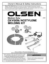
Oxy-Acetylene Welding Tip Chart
Complete Assembly - Part # QW
Heating Nozzle Assembly - Part # QMFA
Elbow Tip - Part # QET
Mixer - Part # QUM

6
OXY-ACETYLENE CUTTING NOZZLE CHART
Cutting Tip Oxygen Acetylene
Part No. Metal Thickness Nozzle Size Pressure (P.S.I.G.) Pressure (P.S.I.G.)
Min. Max. Min. Max.
Q3-101-000 1/8" 000 20 25 3 5
Q3-101-00 1/4" 00 20 25 3 5
Q3-101-0* 1/2" 0 30 35 3 5
Q3-101-1 3/4" 1 30 35 3 5
Q3-101-2 1-1/2" 2 35 45 3 7
Q3-101-3 2-1/2" 3 40 50 4 10
Q3-101-4 3" 4 40 50 5 10
*Supplied with Sabre "V" Medium-Duty Outfit.
Cutting Nozzle - Part # Q3-101

7
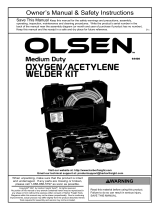
Replacement - Welding Torch and Cuttting Attachment Assemblies:
MAINTENANCE
For all repairs, send the apparatus to ESAB Remanufacturing Center, 411 S. Ebenezer Road, Florence, SC 29501.
Improperly repaired apparatus is hazardous.
CA1350 Cutting Attachment 90° Head - Part # QCA1350
100C Welding Torch - Part # Q100C

SABRE and QC are registered trademarks of ESAB Welding & Cutting Products.
F-15-420 10-2000 Printed in U.S.A.
/