Magnadyne Silencer SL-5 Installation guide
- Category
- Motor vehicle electronics
- Type
- Installation guide
This manual is also suitable for
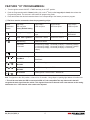
Magnadyne Silencer SL-5 is a professional grade 2-Channel Remote Start with Keyless Entry System, designed for installation in fuel-injected vehicles with automatic transmission only. Once installed and programmed correctly, the device allows the user to start the vehicle remotely, as well as lock and unlock the doors using the included key fobs. It also features a parking light relay, programmable factory rearm, and a negative horn output. Please consult the full user manual for detailed instructions on installation, programming and operation.
Magnadyne Silencer SL-5 is a professional grade 2-Channel Remote Start with Keyless Entry System, designed for installation in fuel-injected vehicles with automatic transmission only. Once installed and programmed correctly, the device allows the user to start the vehicle remotely, as well as lock and unlock the doors using the included key fobs. It also features a parking light relay, programmable factory rearm, and a negative horn output. Please consult the full user manual for detailed instructions on installation, programming and operation.


-
 1
1
-
 2
2
-
 3
3
-
 4
4
-
 5
5
-
 6
6
-
 7
7
-
 8
8
-
 9
9
-
 10
10
-
 11
11
-
 12
12
-
 13
13
-
 14
14
-
 15
15
-
 16
16
-
 17
17
-
 18
18
-
 19
19
-
 20
20
-
 21
21


Magnadyne Silencer SL-5 Installation guide
- Category
- Motor vehicle electronics
- Type
- Installation guide
- This manual is also suitable for
Magnadyne Silencer SL-5 is a professional grade 2-Channel Remote Start with Keyless Entry System, designed for installation in fuel-injected vehicles with automatic transmission only. Once installed and programmed correctly, the device allows the user to start the vehicle remotely, as well as lock and unlock the doors using the included key fobs. It also features a parking light relay, programmable factory rearm, and a negative horn output. Please consult the full user manual for detailed instructions on installation, programming and operation.
Ask a question and I''ll find the answer in the document
Finding information in a document is now easier with AI
Related papers
-
Magnadyne Silencer SL-6S Installation guide
-
-
-
-
-
-
-
-
-
Magnadyne M8a Installation guide
Other documents
-
Autopage C3-RS1100 OLED User manual
-
-
-
 Crime Stopper RS4-G5 Installation guide
-
Python Responder LC Model 991 Installation guide
-
Crimestopper Security Products SP-402 User manual
-
Viper 5601 Installation guide
-
Viper 4816V Owner's manual
-
 Crimestopper Security Products The Informer II CS-2016DP-FM User manual
-
Fortress Technologies The Informer II CS-2016DP-FM User manual

