Page is loading ...

Original operating manual
Assembly and Operating Manual
OPR 061-221
Collision and Overload Protection Sensor

Imprint
2
06.00 | OPR 061-221 | Assembly and Operating Manual | en | 389236
Imprint
Copyright:
This manual is protected by copyright. The author is SCHUNK GmbH & Co. KG. All rights
reserved. Any reproduction, processing, distribution (making available to third parties),
translation or other usage - even excerpts - of the manual is especially prohibited and
requires our written approval.
Technical changes:
We reserve the right to make alterations for the purpose of technical improvement.
Document number: 389236
Version: 06.00|26/11/2019|en
© SCHUNK GmbH & Co. KG
All rights reserved.
Dear Customer,
thank you for trusting our products and our family-owned company, the leading
technology supplier of robots and production machines.
Our team is always available to answer any questions on this product and other solutions.
Ask us questions and challenge us. We will find a solution!
Best regards,
Your SCHUNK team
SCHUNK GmbH & Co. KG
Spann- und Greiftechnik
Bahnhofstr. 106 – 134
D-74348 Lauffen/Neckar
Tel. +49-7133-103-0
Fax +49-7133-103-2399
schunk.com

Table of Contents
06.00 | OPR 061-221 | Assembly and Operating Manual | en | 389236
3
Table of Contents
Glossary of Terms .................................................................................................... 5
1 General.................................................................................................................... 6
1.1 About this manual ................................................................................................ 6
1.1.1 Presentation of Warning Labels ...............................................................6
1.1.2 Applicable documents ..............................................................................7
1.2 Warranty .............................................................................................................. 7
2 Basic safety notes ................................................................................................... 8
2.1 Intended use......................................................................................................... 8
2.2 Not intended use.................................................................................................. 8
2.3 Constructional changes ........................................................................................ 8
2.4 Spare parts ........................................................................................................... 8
2.5 Ambient conditions and operating conditions .....................................................9
2.6 Personnel qualification......................................................................................... 9
2.7 Personal protective equipment.......................................................................... 10
2.8 Notes on safe operation ..................................................................................... 10
2.9 Transport ............................................................................................................ 10
2.10 Malfunctions....................................................................................................... 11
2.11 Disposal .............................................................................................................. 11
2.12 Notes on particular risks..................................................................................... 11
3 Technical data.........................................................................................................12
4 Design and description............................................................................................13
4.1 Introduction........................................................................................................ 13
4.2 Description ......................................................................................................... 14
5 Assembly ................................................................................................................15
5.1 Mechanical connection ...................................................................................... 15
5.2 Electrical connection .......................................................................................... 17
5.2.1 Switch Adjustment..................................................................................18
6 Operation ...............................................................................................................25
7 Troubleshooting .....................................................................................................26
8 Maintenance ..........................................................................................................27
8.1 General ............................................................................................................... 27
8.2 OPR with the Spring Assist Option...................................................................... 28
8.3 Cable Replacement............................................................................................. 28
8.4 Replacement of connector block assembly........................................................ 28
8.4.1 Replacement of connector block assembly for OPR 061........................29
8.4.2 Replacement of connector block assembly for OPR 081 - 221...............32
8.5 Re-lubrication ..................................................................................................... 34

Table of Contents
4
06.00 | OPR 061-221 | Assembly and Operating Manual | en | 389236
9 Drawings.................................................................................................................38
9.1 OPR 61 ................................................................................................................ 38
9.2 OPR 081 .............................................................................................................. 39
9.3 OPR 101 .............................................................................................................. 40
9.4 OPR 131 .............................................................................................................. 41
9.5 OPR 176 .............................................................................................................. 42
9.6 OPR 221 .............................................................................................................. 43
9.7 Dust and splashing water protection ................................................................. 44
10 Translation of original declaration of incorporation ................................................45
11 Annex to Declaration of Incorporation....................................................................46

Glossary of Terms
Glossary of Terms
Adapter Plate
Optional component used to adapt the
OPR Body or Stem to the user’s robot
or tooling.
Body
Cylindrical aluminum housing and air
pressure chamber. An adap-ter plate to
the user’s robot is usually attached
here.
Cam
A hardened steel ring mounted inside
the cover on which the hardened steel
ball segments mounted to the stem are
nested.
Collision
The accidental impact between a tool
and some obstruction in its path.
Collision Sensing Switch
A switch that changes state to an
circuit when a crash is detected. It is
mounted in a threaded hole in the side
of the body under the connector block.
The steel target moves out of range in
the event of a crash.
Cover Plate
Disk-shaped aluminum cover for OPR
Body.
M8, 3-Pin Male Threaded Connector
8mm electrical connector mounted in a
block attached to the side of the Body.
Piston
The component which, together with
the Body, creates a pressure chamber.
Varying the pressure in this chamber
varies the load required to move the
piston.
Reset
The ability of the OPR to return to its
centrical working position when a
disturbing force or displacement is
removed.
Stem
Round, conical steel element with
threaded holes and dowel pin holes. An
adapter plate to the user’s tooling is
usually attached here.
06.00 | OPR 061-221 | Assembly and Operating Manual | en | 389236
5

General
6
06.00 | OPR 061-221 | Assembly and Operating Manual | en | 389236
1 General
1.1 About this manual
This manual contains important information for a safe and
appropriate use of the product.
This manual is an integral part of the product and must be kept
accessible for the personnel at all times.
Before starting work, the personnel must have read and
understood this operating manual. Prerequisite for safe working is
the observance of all safety instructions in this manual.
Illustrations in this manual are provided for basic understanding
and may differ from the actual product design.
In addition to these instructions, the documents listed under
Applicable documents [}7] are applicable.
1.1.1 Presentation of Warning Labels
To make risks clear, the following signal words and symbols are
used for safety notes.
DANGER
Danger for persons!
Non-observance will inevitably cause irreversible injury or death.
WARNING
Dangers for persons!
Non-observance can lead to irreversible injury and even death.
CAUTION
Dangers for persons!
Non-observance can cause minor injuries.
CAUTION
Material damage!
Information about avoiding material damage.

General
06.00 | OPR 061-221 | Assembly and Operating Manual | en | 389236
7
1.1.2 Applicable documents
• General terms of business *
• Catalog data sheet of the purchased product *
The documents marked with an asterisk (*) can be downloaded on
our homepage schunk.com
1.2 Warranty
If the product is used as intended, the warranty is valid for 24
months from the ex-works delivery date under the following
conditions:
• Observe the specified maintenance and lubrication intervals
• Observe the ambient conditions and operating conditions
Parts touching the workpiece and wear parts are not included in
the warranty.

Basic safety notes
8
06.00 | OPR 061-221 | Assembly and Operating Manual | en | 389236
2 Basic safety notes
2.1 Intended use
The OPR was designed as a device to protect industrial
components and machinery from damage resulting from collisions
and impacts.
The OPR has not been designed for, nor should it be used in,
situations involving the safety of humans or animals. In all
situations the user is responsible for insuring that applicable safety
practices are followed as outlined by the manufacturer of the
equipment on which the OPR will be used.
The module is intended for installation in a machine/system. The
requirements of the applicable guidelines must be observed and
complied with.
The module may be used only in the context of its defined
application parameters Technical data [}12].
Any other use or use exceeding that specified is an infringement of
use for intended purpose. The manufacturer bears no liability for
damage resulting from such use.
2.2 Not intended use
It is not intended use if the product is used, for example, as a
pressing tool, stamping tool, lifting gear, guide for tools, cutting
tool, clamping device or a drilling tool.
• Any utilization that exceeds or differs from the appropriate use
is regarded as misuse.
2.3 Constructional changes
Implementation of structural changes
By conversions, changes, and reworking, e.g. additional threads,
holes, or safety devices can impair the functioning or safety of the
product or damage it.
• Structural changes should only be made with the written
approval of SCHUNK.
2.4 Spare parts
Use of unauthorized spare parts
Using unauthorized spare parts can endanger personnel and
damage the product or cause it to malfunction.
• Use only original spare parts or spares authorized by SCHUNK.

Basic safety notes
06.00 | OPR 061-221 | Assembly and Operating Manual | en | 389236
9
2.5 Ambient conditions and operating conditions
Required ambient conditions and operating conditions
Incorrect ambient and operating conditions can make the product
unsafe, leading to the risk of serious injuries, considerable material
damage and/or a significant reduction to the product's life span.
• Make sure that the product is used only in the context of its
defined application parameters, Technical data [}12].
• Make sure that the product is a sufficient size for the
application.
• Make sure that the environment is free from splash water and
vapors as well as from abrasion or processing dust. Exceptions
are products that are designed especially for contaminated
environments.
2.6 Personnel qualification
Inadequate qualifications of the personnel
If the personnel working with the product is not sufficiently
qualified, the result may be serious injuries and significant
property damage.
• All work may only be performed by qualified personnel.
• Before working with the product, the personnel must have read
and understood the complete assembly and operating manual.
• Observe the national safety regulations and rules and general
safety instructions.
The following personal qualifications are necessary for the various
activities related to the product:
Trained electrician Due to their technical training, knowledge and experience, trained
electricians are able to work on electrical systems, recognize and
avoid possible dangers and know the relevant standards and
regulations.
Qualified personnel Due to its technical training, knowledge and experience, qualified
personnel is able to perform the delegated tasks, recognize and
avoid possible dangers and knows the relevant standards and
regulations.
Instructed person Instructed persons were instructed by the operator about the
delegated tasks and possible dangers due to improper behaviour.
Service personnel of
the manufacturer
Due to its technical training, knowledge and experience, service
personnel of the manufacturer is able to perform the delegated
tasks and to recognize and avoid possible dangers.

Basic safety notes
10
06.00 | OPR 061-221 | Assembly and Operating Manual | en | 389236
2.7 Personal protective equipment
Use of personal protective equipment
Personal protective equipment serves to protect staff against
danger which may interfere with their health or safety at work.
• When working on and with the product, observe the
occupational health and safety regulations and wear the
required personal protective equipment.
• Observe the valid safety and accident prevention regulations.
• Wear protective gloves to guard against sharp edges and
corners or rough surfaces.
• Wear heat-resistant protective gloves when handling hot
surfaces.
• Wear protective gloves and safety goggles when handling
hazardous substances.
• Wear close-fitting protective clothing and also wear long hair in
a hairnet when dealing with moving components.
2.8 Notes on safe operation
Incorrect handling of the personnel
Incorrect handling and assembly may impair the product's safety
and cause serious injuries and considerable material damage.
• Avoid any manner of working that may interfere with the
function and operational safety of the product.
• Use the product as intended.
• Observe the safety notes and assembly instructions.
• Do not expose the product to any corrosive media. This does
not apply to products that are designed for special
environments.
• Eliminate any malfunction immediately.
• Observe the care and maintenance instructions.
• Observe the current safety, accident prevention and
environmental protection regulations regarding the product's
application field.
2.9 Transport
Handling during transport
Incorrect handling during transport may impair the product's
safety and cause serious injuries and considerable material
damage.
• When handling heavy weights, use lifting equipment to lift the
product and transport it by appropriate means.
• Secure the product against falling during transportation and
handling.
• Stand clear of suspended loads.

Basic safety notes
06.00 | OPR 061-221 | Assembly and Operating Manual | en | 389236
11
2.10 Malfunctions
Behavior in case of malfunctions
• Immediately remove the product from operation and report the
malfunction to the responsible departments/persons.
• Order appropriately trained personnel to rectify the
malfunction.
• Do not recommission the product until the malfunction has
been rectified.
• Test the product after a malfunction to establish whether it still
functions properly and no increased risks have arisen.
2.11 Disposal
Handling of disposal
The incorrect handling of disposal may impair the product's safety
and cause serious injuries as well as considerable material and
environmental harm.
• Follow local regulations on dispatching product components for
recycling or proper disposal.
2.12 Notes on particular risks
WARNING
Risk of injury from falling of the unit during transport, assembly
and operation!
•Secure gripper unit during transport and assembly with
adequately sized straps.
•Ensure careful cultivation of the collision and overload system
to the machine.
WARNING
Risk of injury from crushing fingers during deflection process!
WARNING
Risk of injury from overload signal of the sensor (eg electrical
short circuit) and in case of failure and reducing the supply of
compressed air! The function of the electrical signal transmission
is no longer guaranteed.

Technical data
12
06.00 | OPR 061-221 | Assembly and Operating Manual | en | 389236
3 Technical data
Standard for quality of the
compressed air
clean, dry, non-lubricated compressed air from
a
self-relieving regulator
Pressure range min./max. [bar] OPR-...-P00: 1.4 / 6.2
OPR-...-P05: 1.4 / 5.9 OPR-...-P10: 1.4 / 5.5
OPR-...-P15: 1.4 / 5.2
Ambient temperature [°C] 5 to +50
IP rating standard
splashing
water
protection
54
65
Connector Type
Switch Rating
OPR 061 M8-3-pin male
threaded connector
100 mA
10-30 VDC
OPR 081-221 3-pole Nano Connector
125 mA
28 V~/=
Optional auxiliary springs available corresponding to 0.3, 0.7, 1 bar
Noise emission [dB(A)] ≤ 70
More technical data is included in the catalog data sheet.
Whichever is the latest version.

Design and description
06.00 | OPR 061-221 | Assembly and Operating Manual | en | 389236
13
4 Design and description
4.1 Introduction
The OPR is a pneumatically pressurized device offering protection
to industrial robots and tooling in the event of accidental impacts
and unanticipated loads. The unit works by “breaking away” from
its working geometry in the event of excessive torsional, moment,
or compressive axial forces, or any combination of these.
The OPR cannot respond to pure axial tension, which is an unlikely
mode of loading. Removal of the upsetting force or moment
allows the OPR to return to its initial position.
As a collision occurs, internal motion of the OPR components
cause a switch to change state (OPR-061: Change to an open
circuit / OPR-081-221: Cause a normally closed switch to open).
The switch circuit may be monitored by robotic controllers to stop
operations before damage to the robot or tooling occurs. The load
threshold at which the OPR breaks away is adjustable by
controlling the air pressure supplied to the unit. The amount of
compliance (travel) provided by the OPR before the switch circuit
opens is adjustable by turning a switch adjustment screw.
All OPR devices provide axial (compression only), torsional, and
moment compliance.

Design and description
14
06.00 | OPR 061-221 | Assembly and Operating Manual | en | 389236
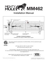
4.2 Description
Adapter Plate
Tool Side
(option)
Stem
Switch/Connector
Block Assembly
Nano
Connector
Adapter Plate
Robot Side
(option)
Cover Plate
Body
Pneumatic Port
The OPR consists of a piston housing (body) closed with a cover
plate assembly. A stem assembly protrudes through the cover
plate assembly. The cover plate assembly incorporates a cam to
accurately and repeatably position the stem assembly. The stem
assembly is forced into position against the cam by a piston. The
piston is supported by user supplied compressed air and an
optional assist spring. The stem provides a mounting surface for
customized interface plates. Tapped and through holes on the
back surface of the body allow direct bolting of the body to user
tooling. All load bearing components and those with wear surfaces
are made of hard-coat anodized aluminium, hardened bearing
steel, or hardened tool steel.
A Collision Sensing Switch is positioned in the side of the body. A
connector block assembly containing a M8, 3-pin male threaded
connector is mounted on the side of the OPR body. The user
connects to the switch using the M8 connector for which a variety
of cables are available. The user must also supply the OPR with
dry, regulated, compressed air through a port on the side of the
OPR body. The size and location of these connections are shown in
the drawing provided at the end of this manual.

Assembly
06.00 | OPR 061-221 | Assembly and Operating Manual | en | 389236
15
5 Assembly
Protect electrical cables and compressed air lines as much as
possible against tensile strain, kinking, breakage etc. when laying.
CAUTION
Prior to establishing or branching the compressed air line to the
OPR, ensure that the compressed air supply is switched off and
that enclosed compressed air has been discharged.
CAUTION
The level of desired or required air pressure will vary according
to the weight, loading, and motion of the user’s tooling.
When the pneumatically-supplied force is sufficient to re-seat the
OPR, the tooling will move to its working position.
•Exercise caution while increasing the air pressure supplied to
the OPR.
5.1 Mechanical connection
The OPR is usually installed with the housing facing the robot and
the broach facing the insert tool, yet users can decide this for
themselves.
The OPR can be attached directly to a robot or insert tool with the
help of the alignment pin and through-hole / thread bores. Where
this is not possible, please use an adapter plate.
CAUTION
The surface to which the OPR body is mounted must be flat and
smooth and provide support for the entire surface of the body.
A second interface plate is often required for mounting to the OPR
stem. Such adapterplates may be ordered from SCHUNK as blank
plates or machined as necessary for specific applications. Another
option is for the user to fabricate their own interface plates. Once
any required machining of the adapter plates is complete, mount
the OPR using hardware appropriately sized for the application.
Connect an appropriately sized air line and fitting to the OPR.
Do not supply air pressure at this time.
All mounting hardware should be tightened. The use of an
industrial thread-locking compound is recommended for all
fasteners.

Assembly
16
06.00 | OPR 061-221 | Assembly and Operating Manual | en | 389236
CAUTION
unexpected movement of the OPR
Personal injury or damage to equipment is possible
•Before connecting or uncoupling the air supply to the OPR,
ensure that the air supply is turned off and that all trapped air
has been vented
Fastener Torque Specifications
Type Screw [mm] Tightening torque [Nm]
OPR-061 M4 - 40 mm 4.4 - 5.1 Nm
OPR-081 M5 - 45 mm 5.0 - 6.8 Nm
OPR-101 M5 - 50 mm 5.0 - 6.8 Nm
OPR-131 M6 - 69 mm 9.0 - 11.9 Nm
OPR-176 M8 - 80 mm 21.5 - 28.2 Nm
OPR-221 M10 - 100 mm 44.0 - 58.8 Nm

Assembly
06.00 | OPR 061-221 | Assembly and Operating Manual | en | 389236
17
5.2 Electrical connection
For connection to the user’s controls, the OPR is equipped with a
collision sensing switch. When the OPR is in the collision mode or
the electrical cable to the switch is disconnected an open circuit is
generated.
Following you can find the connections between the internal switch
and the pins in the Connector Block Assembly. Optional mating
cables, available from SCHUNK Mechanical connection [}15], utilize
the brown-black-blue color code indicated.
OPR-061
PNP Switch (standard)
NPN Switch (optional)
switch wiring:
switch wiring:
switch test circuit:
switch test circuit:
Inside OPR Inside OPR
Inside OPR Inside OPR
PNP proximity switch PNP proximity switch
NPN proximity switch NPN proximity switch
Brown Brown
Brown Brown
Blue
Blue
Blue
Blue
Black
Black
Black
Black
RL
RL
(+ V) (+ V)
(+ V)
(+ V)
(0 V) (0 V)
(0 V) (0 V)
switch rating:
switch rating: 100 mA (Max.)
at 10-30 VDC
100 mA (Max.)
at 10-30 VDC LED test light with current limiting
resistor 100 mA (Max.) at 10-30 VDC
LED test light with current limiting
resistor 100 mA (Max.) at 10-30 VDC
* Provided by customer
* Provided by customer
Switch wiring as a normaly-open PNP or NPN proximity switch

Assembly
18
06.00 | OPR 061-221 | Assembly and Operating Manual | en | 389236
OPR-081-221
NC Switch
Inside OPR
Blue
Black
Brown
Switch wiring as a normaly-closed , dry contact switch
NOTE
The user is responsible for connecting the OPR to their controls
and providing an “electrical load” in series with the collision
sensing switch.
• The switches of type OPR 81 - 221 are suitable for electrical
signals of max. 125 mA, 28 V AC or DC.
• The switch of the type OPR 61 is suitable for electrical signals of
max. 100 mA at 10 - 30 VDC.
• The desired or required pressure of the compressed air
depends on the weight, load and movement of the attached
tools. Resetting the compressed air of the OPR moves the tool
to its working position.
Once the OPR has been installed and connected as described in
the preceding paragraphs proper electrical operation of the unit
may be confirmed.
ØSupply the OPR with approximately 1 bar and ensure that the
unit is electrically connected to the user’s control circuit or to a
test box.
✓The switch should appear closed.
ØManually push the OPR to simulate a collision while observing
the switch output. .
✓When the collision occurs the switch will open and the test
light will turn off
ØRelease the OPR and it will return to its working position.
✓The test light will illuminate
5.2.1 Switch Adjustment
OPR 061: Switch Adjustment for OPR 061 [}19]
OPR 081 - 221: Switch Adjustment for OPR 081 - 221 [}22]

Assembly
06.00 | OPR 061-221 | Assembly and Operating Manual | en | 389236
19
5.2.1.1 Switch Adjustment for OPR 061
Larger Connector Block Small Connector Block
Adjustment Set Screw
Old version New version
There are two styles of connector block assemblies. The Old
version has a larger connector body than the New version. The
New version has an adjustment set screw in the side of the
connector body.
Switch adjustment of
Old version NOTE
The switch is factory adjusted to open after the stem has traveled
0.5 mm in the axial direction. Adjustments should only be made if
replacing the switch.
ØDe-energize all electrical and pneumatic power supplied to the
OPR. Drain all stored air and electric power in compliance with
standard (OSHA) safety practices and standards.
ØDisconnect the air lines and signal wires connected to the OPR.
ØRemove the user-installed mounting hardware from the OPR
and remove the unit. Take the unit to a test bench equipped
with a clean working surface and compressed air.
ØEnsure that the OPR returns to its Reset or Working position
with the stem fully extended and the alignment mark on the
stem in line with the alignment mark on the cover plate.
(Temporarily supply approx. 4 bar to the unit.)

Assembly
20
06.00 | OPR 061-221 | Assembly and Operating Manual | en | 389236
Dial
indicator
Interface
Plate
Arbor
Press
Arbor
Press Ram
Sensor
Lock Nut
Sensor
ØLoosen and remove the screw holding the connector block in
place.
ØTaking care not to break the wires, pull the connector block away
from the body. Loosen the locknut on the proximity switch.
ØConnect a test box Electrical connection [}17].
ØAttach an interface plate to the stem of the OPR.
ØCenter the OPR under the press ram.
ØSet a dial indicator in contact with the interface plate and adjust
it so that the probe is vertical. Set the dial indicator height so
that it can read at least 1.5mm stroke. Set the dial ring to zero.
ØPush on the press handle until the switch circuit opens and
check the distance traveled on the dial indicator.
ØIf the distance traveled is greater than desired turn the
proximity switch counterclockwise. If the distance traveled is
less turn the proximity switch clockwise.
ØRepeat the two previous steps as necessary to obtain the
desired switch setting.
ØTighten the locknut on the proximity sensor.
ØSlide the connector block over the proximity sensor carefully
routing the wires into the slotted area under the proximity
sensor. Line up the dowel pin with the hole in the body and the
screw hole with the threaded hole in the body.
ØApply Loctite® 222MS to the M3 mounting screw and thread it
into the body. Tighten the screw securely.
ØRe-install the OPR using the user-installed mounting hardware.
CAUTION
Before putting the OPR back into operation, confirm that the
switch is functioning properlyElectrical connection [}17].
/