Page is loading ...

1
Empire
Elliptical
OWNER’S MANUAL
Please carefully read this entire manual before operating your new elliptical
SPT0045

Product Registration………………………………………………………………………….. 1
Important Safety Instructions………………………………………………………………… 2
Important Electrical Information……………………………………………………………… 3
Important Operation Instructions…………………………………………………………….. 3
Assembly Instructions…………………………………………………………………………. 4
Operation of Your New Elliptical……………………………………………………………... 11
Maintenance……………………………………………………………………………………. 15
Parts list…………………………………………………………….…………………………… 16
Explode Drawing…………………………………………………………….…………………. 19
Warranty / Service……………………………………………………………………………… 20
ATTENTION-
THIS ELLIPTICAL IS INTENDED FOR RESIDENTIAL USE
ONLY AND IS WARRANTED FOR THAT APPLICATION. ANY OTHER
APPLICATION VOIDS THIS WARRANTY IN ITS ENTIRETY.
Table of Contents

1
Congratulations on your new elliptical and welcome to the Spirit family!
Thank you for your purchase of this quality elliptical trainer from Spirit Manufacturing, Inc. Your
new elliptical was manufactured by one of the leading fitness manufacturers in the world and is
backed by one of the most comprehensive warranties available. Through your dealer, Spirit will
do all we can to make your ownership experience as pleasant as possible for many years to
come. If not purchased direct from Spirit, the local dealership where you purchased this elliptical
is your administrator for all Spirit warranty and service needs. Their responsibility is to provide
you with the technical knowledge and service personnel to make your experience more
informed and any difficulties easier to remedy.
Please take a moment at this time to record the name of the dealer, their telephone number, and
the date of purchase below to make any future, needed contact easy. We appreciate your
support and we will always remember that you are the reason that we are in business. Please
complete and mail your registration card today and enjoy your new elliptical trainer.
Yours in Health,
BOYLES FITNESS Equipment Pty Ltd.
Name of Dealer______________________________________
Purchase Date_______________________________________
empire_SPT0045_ver.A

2
WARNING - Read all instructions before using this appliance.
Do not operate
elliptical
on deeply padded, plush or shag carpet. Damage to both
carpet and
elliptical
may result.
Keep children away from the
elliptical
.
Keep hands away from all moving parts.
Never operate the elliptical if it has a damaged cord or plug. If the elliptical is not working
properly, call your dealer.
Keep the cord away from heated surfaces.
Do not operate where aerosol spray products are being used or where oxygen is
being administered. Sparks from the motor may ignite a highly gaseous environment.
Never drop or insert any object into any openings.
Do not use outdoors.
To disconnect, turn all controls to the off position, then remove the plug from the outlet.
Do not attempt to use your
elliptical
for any purpose other than for the purpose it is
intended.
The hand pulse sensors are not medical devices. Various factors, including the user’s
movement, may affect the accuracy of heart rate readings. The pulse sensors are
intended only as exercise aids in determining heart rate trends in general.
Wear proper shoes. High heels, dress shoes, sandals or bare feet are not suitable
for use on your
elliptical
. Quality athletic shoes are recommended to avoid leg fatigue.
Maximum User Weight: 120 kgs
SAVE THESE INSTRUCTIONS - THINK SAFETY!
Important Safety Instructions

3
WARNING!
NEVER remove any cover without first disconnecting AC power supply.
If A.C. voltage varies by ten percent (10%) or more, the performance of your elliptical may be
affected. Such conditions are not covered under your warranty. If you suspect the voltage is
low, contact your local power company or a licensed electrician for proper testing.
NEVER expose this
elliptical
to rain or moisture. This product is NOT designed for
Use outdoors, near a pool or spa, or in any other high humidity environment. Maximum
environmental ratings are 4-48 degrees Celsius, 95% humidity non-condensing (no water
droplets forming on surfaces).
NEVER operate this elliptical without reading and completely understanding the results of any
operational change you request from the computer.
Understand that changes in resistance do not occur immediately. Set your desired level on
the computer console and release the adjustment key. The computer will obey the command
gradually.
NEVER use your elliptical during an electrical storm. Surges may occur in your household
power supply that could damage elliptical components.
Use caution while participating in other activities while using your elliptical such as watching
television, reading, etc. These distractions may cause you to lose balance and may result in
serious injury.
Always hold on to a handrail or hand bar while making control changes.
Do not use excessive pressure on console control keys. They are precision set to properly
function with little finger pressure. Pushing harder is not going to make the unit go faster or
slower. If you feel the buttons are not functioning properly with normal pressure, contact your
Spirit dealer.
Important Electrical Information
Important Operation Instructions

4
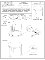
Step 1
Step 2
#97. 5/16" x 23 x 1.5T
Flat Washer (2pcs)
#70. 5/16" x 15m/m
Hex Head Bolt (2pcs)
#101. Ø17
Wavy Washer (2pcs)
#75. 5/16" x 15m/m
Button Head Socket Bolt (6pcs)
#71. 5/16" x 32m/m
Hex Head Bolt (2 pcs)
#98. 5/16" x 20 x 1.5T
Flat Washer
(4 pcs)
#105. 5/16" x 7T
Nyloc Nut (2 pcs)
#89. 3/8" x 7T
Nyloc Nut (2 pcs)
#94. 3/8" x 19 x 1.5T
Flat Washer (2 pcs)
Step 3
#76. 5/16" x 3/4"
Button Head Socket Bolt (2 pcs)
#77. 3/8" x 2-1/4"
Button Head Socket Bolt (2 pcs)
#70. 5/16" x 15m/m
Hex Head Bolt (6pcs)
#97. 5/16"x 23 x1.5T
Flat Washer (4pcs)
#102. 5/16"x 23 x2T
Curved Washer (2pcs)
#78. M5 x 10m/m
Phillips Head Screw (4pcs)
Assembly
Pack Check List

5
s
#84. 3.5x12m/m
Sheet Metal Screw (8pcs)
Step4
Tools
#108. Combination M5 Allen Wrench
& Phillips Head Screw Driver (1 pc)
#110. 12m/m Wrench ( 1pc)
#111. 13/14m/m Wrench ( 2pcs)
Assembly
Pack Check List

6
UNPACKING THE UNIT
1. Using a razor knife (Box Cutter) cut the outside, bottom, edge of box along the dotted Line. Lift Box over the
unit and unpack.
2. Carefully remove all parts from carton and inspect for any damage or missing parts. If damaged parts are found,
or parts are missing, contact your dealer immediately.
3. Locate the hardware package. The hardware is separated into steps. Remove the tools first. Remove the
hardware for each step as needed to avoid confusion.
PLEASE ENSURE ALL FASTENERS ARE TIGHT AFTER THE COMPONENTS HAVE
BEEN ASSEMBLED.
POWER CONNECTOR LOCATED ON
FRONT, LEFT HAND SIDE OF UNIT.
Assembly Instructions

7
STEP 1: CONSOLE MAST ASSEMBLY
1. Locate the Console Mast (10) and Console Mast Cover (41) and slide the Cover onto the Mast
as far as it will go. Make sure the Console Mast Cover (41) is facing the correct way.
2. At the top opening of the Main Frame (1) of the elliptical is a Computer Cable (32). Unravel and
straighten out the Computer Cable (32) and feed it into the bottom of the Console Mast tube (10)
and out of the top opening.
3. Install the Console Mast (10) into the receiving bracket in the top of the Main Frame (1).
4. Put the 4pcs of 5/16"× 23 ×1.5T Flat Washers (97) onto the 4pcs of 5/16" × 15m/m Hex Head
Bolts (70) and the 2pcs of 5/16” × 23 × 2T Curved Washers (102) onto the 2pcs of 5/16" ×15m/m
Hex Head Bolts (70). Install, and hand tighten by using the 12m/m Wrench (110).
5. NOTE: There is a electrical wire running through the Console Mast Tube (10). Be careful not to
damage or pinch this Computer Cable (32) during this procedure.
6. Locate the Console (31) and the 4 pcs of M5 × 10m/m Phillips Head Screws (78) by using the
Combination M5 Allen Wrench & Phillips Head Screw Driver (108).
7. There will be three electrical wire connectors at the top opening of the Console Mast (10), two
Handpulse Assembly (37), one Computer Cable (32). Connect these to the mating connectors
on the back of the Console (31). The connectors are keyed so you cannot plug them in the
wrong way so do not force them.
8. Storing the excess wire back into the Console Mast (10), carefully install the Console (31) onto
the mounting plate of Console Mast (10) and secure using the 4 pcs of M5 × 10m/m Phillips
Head Screws (78).

8
STEP 2: HANDLE BAR ASSEMBLY
1. Install the 2 pcs of Ø17 Wave Washers (101) onto the Left and Right side of the Handle Bar axle.
2. Slide the Lower Handle Bar (L&R) (4&5) onto the appropriate side of the axle.
3. Put the 2 pcs of 5/16" × 23 × 1.5T Flat Washers (97) onto the 2 pcs of 5/16" × 15m/m Hex Head Bolts
(70) and install, and tighten, in the threaded holes in the ends of the axle.
4.
Install the Left and Right Handgrip (13&14) into the Lower Handle Bar (L&R) (4&5) with 6pcs of
5/16 ×15m/m Button Head Socket Bolts (75) by using the Combination M5 Allen Wrench & Phillips
Head Screw Driver (108).

9
STEP 3: CONNECTING ARM ASSEMBLY
1. Align the hole in the end of the Connecting Arms (L&R)(7&8)(pivoting rod end) with the
hole in the bracket of the Lower Handle Bar (L&R) (4&5). The rod end should be on the
inside of the Lower Handle Bar (L&R) (4&5). bracket. Take 2pcs of 5/16"×1-1/4" Hex Head
Bolts (71) and install it through the Lower Handle Bar (L&R) (4&5)) bracket and the rod end.
Install 2pcs of 5/16"×20×1.5T Flat Washers (98), 2pcs of 5/16"×7T Nylon Nuts(105) tighten
firmly using the 12m/m Wrench (110) on the 5/16"×7T Nylon Nut (105)and one on the
5/16"×1-1/4" Hex Head Bolt (71).
2. Install the 2 pcs of Rails (15) into the receiving bracket in the end of Main Frame(1) with 2 pcs of
3/8” × 2-1/4” Button Head Socket Bolts (77) , 2pcs of 3/8"×19×1.5T Flat Washers(94) and 2 pcs
of 3/8"×7T Nylon Nuts (89) by using 2 pcs of 13/14m/m Wrench(111).
3. Put the Lug Cover (L) (61) and Lug Cover (R)(62) onto the Rail Strap (16). Install the Rail
Tubes (15) with 2 pcs of 5/16” ×3/4” Button Head Socket Bolts (76) and 2 pcs of
5/16"×20×1.5T Flat Washers (98) by using Combination M5 Allen Wrench & Phillips Head
Screw Driver (108).

10
STEP 4: PLASTICS ASSEMBLY
1. Install the Connecting Arm Covers (L & R) (59 & 60) over the connection of the rod end
and Lower Handle Bar (L&R) (4&5) with 4pcs of M5×15m/m Phillips Head Screws(79)
and 2pcs of Ø 3.5×12m/m Sheet Metal Screws (84) by using the Combination M5 Allen
Wrench & Phillips Head Screw Driver (108).
2. Install the 2pcs of Slide Wheel Cover (52) using the 4pcs of M5×15m/m Phillips Head
Screws(79).
3. Install the Front Handle Bar Cover (L & R) (54 & 56) and Rear Handle Bar Cover (L & R)
(55 & 57) over the Handle Bars axle connections with the 6 pcs of Ø 3.5×12m/m Sheet
Metal Screws (84) by using Combination M5 Allen Wrench & Phillips Head Screw Driver
(108).

11
The
elliptical
is equipped with two transport wheels which are engaged when rear of
the Elliptical is lifted.
Getting familiar with the control panel
Starting a program
Quick Start
After the console powers up you may press the Start key to begin, this will initiate the Quick Start
mode. In Quick Start the Time will count up from zero and the workload may be adjusted manually
by pressing the Up/Down buttons. Distance and Calories will accrue, starting from zero.
The Calorie window will switch between Calories and Watts every 5 seconds. The Calorie reading
shows total Calories burned and is an approximate number. The Watt reading indicates how much
work you are doing. If the Watt reading is 100, this means you are doing enough work to light a 100
watt light bulb.
The bottom left data window will switch between RPM and Speed every 5 seconds. The Distance
window shows distance traveled, based on pedal speed, in miles. The Pulse window will display
your heart rate in beats per minute if you are holding the heart rate hand sensors, or wearing a
chest strap transmitter.
Operation of Your Elliptical
Transportation

12
Manual
Using the Up/Down keys, highlight the Manual icon at the top of the display and press Enter key.
The profile will be blinking and you may use the Up/Down keys to adjust the program work level
and then press Enter. The Time window will now be blinking. Use the Up/Down keys to adjust the
program Time and then press Enter. The Distance window will now be blinking and you can adjust a
target Distance using the Up/Down keys then press Enter. Calories will now be blinking, repeat the
same process as above to set, then press Enter. The Watt icon will be blinking. If you choose to set
the Watts then the machine will automatically adjust the workload to maintain continuous work.
What this means is that if you set the Watt to 100 the machine will try to keep you working at a rate
of work that equals 100 Watts (or working at a rate that will keep a 100 Watt light bulb burning).
Watts are determined by the amount of work you are doing. On the Elliptical this means the speed
you are pedaling at combined with the workload of the machine. In Watt mode, if you change your
speed the machine will automatically change the workload to maintain the same Watt level. If you
pedal faster the workload will decrease and if you pedal slower the workload increases.
After adjusting all the parameters, press Start to begin your workout.
Preset Programs
There are 12 preset programs to choose from. After power up, or reset, press the Up/Down keys to
highlight the Program icon. Press the Enter key to enter the program mode. The display will show
P1, for two seconds, then change to the P1 program profile. You may keep pressing the Up/Down
keys to scroll through the 12 programs. When you see a program you want, press the Enter key to
enter. At this point you may press start to begin the program with the default settings or you may
customize the program.
To customize the work level, press the Up key. You will see the profile increase in size. When the
work level is where you like it press the Enter key (If you do not want to customize the profile, just
press the Enter key to bypass).
The Time window will now be blinking. Use the Up and Down keys to adjust the workout time and
then press Enter.
The Distance window will now be blinking. Repeat the same process to set the distance to count
down, if desired, and press Enter.
The Calorie window will now be blinking. Repeat the same process then press Enter.
The Pulse window will now be blinking. Entering a Pulse number will set an alarm that will beep
when your heart rate reaches the programmed number to let you know you have reached your
target.
Once you have set the data you may press Start to begin the program. You may also press Start at
any time during the programming to begin. Any data that is not programmed at that point will count
up from zero.
When the program ends there is a series of audible beeps. You may press Start to restart the
program or press Reset to return to the start-up screen.

13
User Program
This mode allows you to build and save your own custom program.
Press the Up or Down key until the User icon at the top of the display is blinking then press Enter.
The first column of the profile will be blinking. Use the Up/Down keys to adjust the work level then
press Enter. The second column will now be blinking. Repeat the same process as above and
press Enter. Repeat this process until all the columns are adjusted to your liking. All the settings will
be saved as a custom program.
Target HR
This program allows you to set a target heart rate and the machine will automatically adjust the
work load to safely reach the target and maintain that target.
Use the Up/Down keys to select the Target HR program and press Enter. The display will show a
number and the age icon at top will be blinking. Use the Up/Down keys to adjust the age and press
Enter. The display will now show a blinking percent number or the letters THR.
You may use the Up/Down keys to choose either 55%, 75%, 90% or THR. The percentage
choices will automatically set the target to a percent of your maximum heart rate, based on your
age. This is why it is important to adjust the age properly. The console will use a formula to
determine the correct percentage: 220 – age = maximum HR. For example a 30 year old persons’
Max HR is 190 BPM (220 – 30 = 190 BPM). If the 30 year old wants to work at 75%, their target HR
will be 142BPM.
If you want to choose to work at 75% - for example - then use the Up/Down arrows to highlight 75%
and press Enter. Now the Time window will be blinking and you can program it and other data the
same as other programs. If you want to set your own custom Target HR then use the Up/Down
arrow to highlight THR and press Enter. The Pulse window will now be blinking. Use the Up/Down
arrows to set your own Target HR and press Enter to continue.
Recovery
Used to measure how fast your heart rate (HR) recovers from exercise. The faster your HR returns
to normal from exercise level, the better aerobic shape you are in. Pressing the recovery button will
start a 60 second count down. Hold the hand pulse sensors and do not exercise during the count
down. At the end of the 60 seconds a score will be displayed ranging from F1 to F6 with F1 being
the highest score and F6 being the lowest.

14
FUNCTIONS
TIME: Count up: accumulates training time from zero to 99:59.
Count down: counts down from preset time to zero.
SPEED/ RPM: Automatically toggles between SPEED and RPM every 6 seconds. Speed is in
miles per hour (or kilometers per hour)
DISTANCE: Count up: accumulates training distance from 0.00 to 99.99 miles.
Count down: counts down from preset distance to zero.
CALORIES: Accumulates calories burned from 0 to 9999. This is an estimated number only
to be used from workout to workout to compare your progress. Actual calorie
burn cannot be measured accurately on any consumer exercise equipment
because every individual burns calories at a different rate.
WATTS: Indicates the amount of work being done in Watts.
PULSE: Displays your current heart rate when you grasp the hand sensors or wear the
chest strap transmitter.
LEVEL: Shown next to the workout profile. Indicates the level of work being done from 1
to 16.

15
Maintenance:
1. Wipe down all areas in the sweat path with a damp cloth after each workout.
2. If a squeak, or rough feeling, develops the cause is most likely dirt build-up on the
rear rails and poly-urethane wheels. Clean the rails and wheels with a lint free
cloth and rubbing alcohol. Then apply a small amount of lubricant on the rails with
your fingers or a lint free cloth.
You only need a thin cost of lubrication, wipe off any excess.
3. If squeaks or other noises persist, check that the unit is properly leveled. There
are 4 leveling pads on the bottom of the rear rails, use a 14mm wrench (or
adjustable wrench) to adjust the levelers.

16
NO. DESCRIPTION O'TY
1
Main Frame 1
2
Pedal Arm (L) 1
3
Pedal Arm (R) 1
4
Lower Handle Bar (L) 1
5
Lower Handle Bar (R) 1
6
Bushing Housing, Pedal Arm 2
7
Connecting Arm (L) 1
8
Connecting Arm (R) 1
9
Cross Bar 2
10
Console Mast 1
11
Idler Wheel Assembly 1
12
Crank Axle 1
13
Swing Arm (L) 1
14
Swing Arm (R) 1
15
Rail Tube 2
16 Rail Strap 1
17
Axle for Pedal 2
18
Axle for Slide Wheel 2
19
Rod End Sleeve 3
20
6005_Bearing
2
21
6203_Bearing
6
22
6003_Bearing 8
23
Rod End Bearing 2
24
Ø31 × Ø25.5 × Ø 19 × 16+3T_Bushing 4
25
Steel Cable
1
26
Drive Belt 1
27
Drive Pulley 1
28
Flywheel 1
29 Magnet 1
30
Woodruff Key 2
31
Console Assembly 1
31~1
Console Top Cover 1
31~2
Console Bottom Cover 1
31~3
Badge, Console 1
31~5
Deflector Fan Grill 1
31~6
Fan Grill Anchor 2
31~7
Fan Assembly 1
31~8
Fan Power Switch 1
31~13
300m/m_W/Receiver, HR 1
31~14
Interface Board 1
31~15
Console Display Board 1
31~16
Key Board 1
32
1300m/m_Computer Cable 1
33
750m/m_DC Power Cord 1
Parts List

17
NO. DESCRIPTION O'TY
34
Gear Motor 1
35
400m/m_Sensor W/Cable 1
36
Sensor Rack 1
37
850m/m_Handpulse W/Cable Assembly 2
37~4
Ø3 × 20m/m_Tapping Screw 4
38
Power Adaptor 1
39
Sliding Wheel , Urethane 2
40~1
3/8" × 2"_Flat Head Socket Bolt 2
40~2
Rubber Foot 2
41
Console Mast Cover 1
42 Side Case L
1
43 Side Case R
1
44
Round Disk 2
45
Round Disk Cover 2
46
Cover Swing Arm Axle 2
47
Pedal Arm Cover (L) 1
48
Pedal Arm Cover (R) 1
50
Pedal (L)
1
51
Pedal (R)
1
52
Slide Wheel Cover 2
53
Ø32 (1.8T)_Button Head Plug 4
54
Front Handle Bar Cover (L) 1
55
Rear Handle Bar Cover (L) 1
56
Front Handle Bar Cover (R) 1
57
Rear Handle Bar Cover (R) 1
58
Ø32 (2.5T)_Round Cap 2
59
Connecting Arm Cover (L) 2
60
Connecting Arm Cover (R) 2
61
Lug Cover (L) 1
62
Lug Cover (R) 1
63
Transportation Wheel 2
64
Oval End Cap 2
65
EVA Foam for Rail Strap 1
66
Handgrip Foam 2
67
Rubber Foot 2
68
Drink Bottle 1
69
Spacer Bushing 1
70
5/16" × 15m/m_Hex Head Bolt 20
71
5/16" × 32m/m_Hex Head Bolt 2
72
1/4" × 3/4"_Hex Head Bolt 4
73
3/8" × 2-1/4"_Socket Head Cap Bolt 2
74 M8 × 30m/m_Socket Head Cap Bolt 2
75
5/16" × 15m/m_Button Head Socket Bolt 6
76
5/16" × 3/4"_Button Head Socket Bolt 2
77
3/8" × 2-1/4"_Button Head Socket Bolt 2
78
M5 × 10m/m_Phillips Head Screw 6
79
M5 × 15m/m_Phillips Head Screw 8

18
NO. DESCRIPTION O'TY
80
5 × 16m/m_Tapping Screw
7
81
5 × 25m/m_Tapping Screw
2
82
4.8 × 38m/m_Sheet Metal Screw
1
83
5 × 16m/m_Tapping Screw
12
84
Ø3.5
× 12m/m_Sheet Metal Screw
8
86
Ø17_C Ring
1
87
M8 × 7T_Nyloc Nut
1
88
1/4" _Nyloc Nut
4
89
3/8" × 7T_Nyloc Nut
2
90
3/8"
-
UNF26 × 4T_Nut
1
91
3/8"
-
UNF26 × 9T_Nut
2
92
3/8" × 7T_Nut
4
94
3/8" × 19 × 1.5T_Flat Washer
9
96
5/16" × 35 × 1.5T
_Flat Washer
2
97
5/16" × 23 × 1.5T_Flat Washer
14
98
5/16" × 20 × 1.5T_Flat Washer
8
99
1/4" × 19m/m_Flat Washer
13
100
J Bolt
1
101
Ø17 _Wave Washer
6
102
5/16" × 23 × 2T_Curved Washer
2
103
M8 × 20m/m_Carriage Bolt
1
104
Ø17 × Ø23.5 × 1T_Flat Wa
sher
2
105
5/16" × 7T_Nyloc Nut
2
106
3.5 × 16m/m_Tapping Screw
3
108
M5_Combination M5 Allen Wrench & Phillips Head Screw
1
110
12m/m_Wrench
1
111
13/14m/m_Wrench
2
112
5 × 19m/m_Tapping Screw
2
133
M5 × 10m/m _Phillips Head Screw
8
135
M8
× 9T _Nyloc Nut
1
136
3/8" × 11T_Nyloc Nut
2
142
3.5 × 16m/m_Sheet Metal Screw
7
143
M8 × 6.3T_Nut
4
144
3/8"
-
UNF26 × 6T_Nut
1
145
Axle Stopper
1
146
M5 × 5m/m_Slotted Set Screws
2
147
Adaptor Power Cord
1
/