
FRENCH
PG. 95
W415-2035 / C / 04.30.21
ADD MANUAL TITLE
Wolf Steel Ltd., 24 Napoleon Rd., Barrie, ON, L4M 0G8 Canada / 103 Miller Drive, Crittenden, Kentucky, USA, 41030
Phone 1 (866) 820-8686 • www.napoleon.com • [email protected]
CERTIFIED TO THE CANADIAN AND AMERICAN NATIONAL STANDARDS:
CSA 2.22 AND ANSI Z21.50 FOR VENTED DECORATIVE GAS APPLIANCES
INSTALLER:
Leave this manual with the appliance
CONSUMER:
Retain this manual for future reference
ADD PRODUCT CODE HERE (TRADE GOTHIC LT STD FONT)
NATURAL GAS MODELS:
PROPANE GAS MODELS:
Product Name / Code
(MUST use title from Price Book)
ADD ____ ILLUSTRATED
ADD PRODUCT IMAGE
CSA /
INTERTEK
LOGO
SAFETY INFORMATION
- Do not store or use gasoline or other
fl ammable vapors and liquids in the vicinity of
this or any other appliance.
- WHAT TO DO IF YOU SMELL GAS:
• Do not try to light any appliance.
• Do not touch any electrical switch; do not
use any phone in your building.
• Immediately call your gas supplier from a
neighbour’s phone. Follow the gas
supplier’s instructions.
• If you cannot reach your gas supplier, call
the fi re department.
- Installation and service must be
performed by a qualifi ed installer, service
agency, or the supplier.
This appliance may be installed in an aftermarket,
permanently located, manufactured home (USA
only) or mobile home, where not prohibited by
local codes.
This appliance is only for use with the type of gas
indicated on the rating plate. This appliance is
not convertible for use with other gases, unless
a certifi ed kit is used.
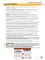
FIRE OR EXPLOSION HAZARD
Failure to follow safety warnings exactly
could result in serious injury, death, or
property damage.
WARNING
!
ENGLISH
$10.00
FOR INDOOR USE ONLY
IF INSTALLATION + OPERATION, ADD SERIAL
NUMBER LABEL HERE
IF SEPARATE MANUALS, ADD “PLACE
BARCODE LABEL ON THE OWNER’S MANUAL”
INSTALLATION MANUAL
LVX38N-1 / LVX50N-1 / LVX62N-1 / LVX74N-1 / LVX38N2-1 / LVX50N2-1 / LVX62N2-1 / LVX74N2-1
LVX38P-1 / LVX50P-1 / LVX62P-1 / LVX74P-1 / LVX38P2-1 / LVX50P2-1 / LVX62P2-1 / LVX74P2-1
Luxuria™ Series
(LVX38-1 illustrated)
GLASS GUARD
THIS APPLIANCE IS INSTALLED WITH
CERTIFIED TO THE CANADIAN AND AMERICAN NATIONAL STANDARDS:
CSA 2.22 AND ANSI Z21.50 FOR VENTED DECORATIVE GAS APPLIANCES
FOR INDOOR USE ONLY
PLACE BARCODE LABEL ON THE
OWNER’S MANUAL

W415-2035 / C / 04.30.21
EN
2
safety information
• This appliance is hot when operated and
can cause severe burns if contacted.
• Any changes or alterations to this
appliance or its controls can be
dangerous and is prohibited.
• Do not operate appliance before reading and
understanding operating instructions. Failure
to operate appliance according to operating
instructions could cause fi re or injury.
• Ensure the glass door is opened or removed
when lighting the pilot for the fi rst time and
when the gas supply has run out.
• Risk of fi re or asphyxiation, do not operate
appliance with fi xed glass removed and never
obstruct the front opening of the appliance.
• Do not connect 110 volts to the control valve,
with the exception of models; GSST8 and
GT8.
• Risk of burns. The appliance should be turned off and cooled before servicing.
• Do not install damaged, incomplete or substitute components.
• Risk of cuts and abrasions. Wear protective gloves, protective footwear, and safety glasses during
installation. Sheet metal edges may be sharp.
• Do not burn wood or other materials in this appliance.
• Provide adequate ventilation and combustion air. Provide adequate accessibility clearance for servicing
and operating the appliance.
• High pressure will damage valve. Disconnect gas supply piping before pressure testing gas line at
test pressures above 1/2 psig. Close the manual shut-off valve before pressure testing gas line at test
pressures equal to or less than 1/2 psig (35mb).
• The appliance must not be operated at temperatures below freezing (32°F / 0°C). Allow the appliance
to warm to above freezing prior to operation, with the exception of models; GSS36, GSS42; these
appliances are suitable for 0°F / -18°C.
• Children and adults should be alerted to hazards of high surface temperature and should stay
away to avoid burns or clothing ignition.
• Young children should be carefully supervised when they are in the same room as the
appliance. Toddlers, young children and others may be susceptible to accidental contact
burns. A physical barrier is recommended if there are at risk individuals in the house. To
restrict access to an appliance or stove, install an adjustable safety gate to keep toddlers,
young children and other at risk individuals out of the room and away from hot surfaces.
• Clothing or other fl ammable material should not be placed on or near the appliance.
• Due to high temperatures, the appliance should be located out of traffi c and away from
furniture and draperies.
• Furniture or other objects must be kept a minimum of 4 feet (1.22m) away from the front of the appliance.
• Ensure you have incorporated adequate safety measure to protect infants/toddlers from touching hot
surfaces.
• Even after the appliance is off, it will remain hot for an extended period of time.
• Check with your local hearth specialty dealer for safety screens and hearth guards to protect children
from hot surfaces. These screens and guards must be fastened to the fl oor.
• Any safety screen, guard or barrier removed for servicing the appliance, must be replaced prior
to operating the appliance.
• It is imperative that the control compartments, burners and circulating blower and its passageway in the
appliance and venting system are kept clean. The appliance and its venting system should be inspected
before use and at least annually by a qualifi ed service person. More frequent cleaning may be required
due to excessive lint from carpeting, bedding material, etc. The appliance area must be kept clear and
free from combustible materials, gasoline and other fl ammable vapors and liquids.
• If the appliance shuts off, do not re-light until you provide fresh air. If appliance keeps shutting off, have it
serviced. Keep burner and control compartment clean.
• Under no circumstances should this appliance be modifi ed.
• Do not allow wind or fans to blow directly into the appliance. Avoid any drafts that alter burner fl ame
patterns.
HOT GLASS WILL CAUSE
BURNS.
DO NOT TOUCH GLASS UNTIL
COOLED.
NEVER ALLOW CHILDREN TO
TOUCH GLASS.
!
DANGER
A barrier designed to reduce the risk of burns from the hot
viewing glass is provided with this appliance and must be
installed for the protection of children and other at-risk
individuals.
!
WARNING

EN
W415-2035 / C / 04.30.21
3
safety information
!
WARNING
• Do not use a blower insert, heat exchanger insert or other accessory not approved for use with this
appliance.
• This appliance must not be connected to a chimney fl ue pipe serving a separate solid fuel burning
appliance.
• Do not use this appliance if any part has been under water. Immediately call a qualifi ed service technician
to inspect the appliance and to replace any part of the control system and any gas control which has
been under water.
• Do not operate the appliance with the glass door removed, cracked or broken. Replacement of the glass
should be done by a licensed or qualifi ed service person, if equipped.
• Do not strike or slam shut the appliance glass door, if equipped.
• Only doors / optional fronts certifi ed with the appliance are to be installed on the appliance.
• Keep the packaging material out of reach of children and dispose of the material in a safe manner. As
with all plastic bags, these are not toys and should be kept away from children and infants.
• Carbon or soot should not occur in a vent free appliance as it can distribute into the living area of your
home. If you notice any signs of carbon or soot, immediately turn off your appliance and arrange to have
it serviced by a qualifi ed technician before operating it again.
• If equipped, the screen must be in place (closed) when the appliance is in operation.
• When equipped with pressure relief doors, they must be kept closed while the appliance is operating
to prevent exhaust fumes containing carbon monoxide, from entering into the home. Temperatures of
the exhaust escaping through these openings can also cause the surrounding combustible materials to
overheat and catch fi re.
• Carbon monoxide poisoning may lead to death; early signs of carbon monoxide poisoning resemble the
fl u, with headache, dizziness and/or nausea. If you have these signs, the appliance may not be working
properly. Get fresh air at once! Have appliance serviced. Some people; pregnant women, persons with
heart or lung disease, anemia, those under the infl uence of alcohol, those at high altitudes are more
affected by carbon monoxide than others. Failure to keep the primary air opening(s) of the burner(s) clean
may result in sooting and property damage.
• As with any combustion appliance, we recommend having your appliance regularly inspected and
serviced as well as having a Carbon Monoxide Detector installed in the same area to defend you and
your family against Carbon Monoxide (not applicable for outdoor appliances).
• Ensure clearances to combustibles are maintained when building a mantel or shelves above the
appliance. Elevated temperatures on the wall or in the air above the appliance can cause melting,
discolouration or damage to decorations, a TV or other electronic components.
• For appliances equipped with a safety barrier; if the barrier becomes damaged, the barrier
shall be replaced with the manufacturer’s barrier for this appliance.
• Installation and repair should be done by a qualifi ed service person. It is imperative that control
compartments, burners and circulating air passageways of the appliance be kept clean.
• For outdoor products only: this appliance must not be installed indoors or within any structure that
prevents or inhibits the exhaust gases from dissipating in the outside atmosphere.
• If applicable, the millivolt version of this appliance uses and requires a fast acting thermocouple. Replace
only with a fast acting thermocouple supplied by Wolf Steel Ltd.
!
WARNING
!
Disconnect the appliance main gas valve/control
from the supply piping when pressure testing that
system at pressures in excess of 1/2 psi (3.5 kPa).
Isolate the appliance with it’s shut off valve during
any pressure testing of the supply piping at
pressures equal to or less than 1/2 psi (3.5 kPa).
FIRE RISK HAZARD / DELAYED IGNITION
High supply pressure will damage the valve / controls.
Add California Prop 65 warning
!
WARNING:
This product can expose you to chemicals including lead and lead compounds,
which are known to the State of California to cause cancer, and chemicals including carbon
monoxide, which are known to the State of California to cause birth defects or other reproduc-
tive harm. For more information, go to www.P65Warnings.ca.gov.

W415-2035 / C / 04.30.21
EN
4
table of contents
1.0 general information 5
1.1 rates and effi ciencies 6
1.2 installation checklist 7
1.3 installation overview 8
1.4 Dynamic Heat Control™ 9
1.5 rating plate/lighting instruction location
11
1.6 mobile home installation 12
1.7 hardware list 12
1.8 lifting handles installation/removal 12
2.0 dimensions 13
2.1 single-sided 13
2.2 see-thru 14
3.0 minimum venting requirements 15
3.1 typical venting installation 17
3.2 minimum air terminal location
clearances 19
3.3 horizontal termination 20
3.4 vertical termination 23
3.5 LVX38-1 venting confi gurations 24
3.6 LVX50-1 / LVX62-1 venting
confi gurations 25
3.7 LVX74-1 venting confi gurations 26
4.0 installation planning 27
4.1 installation option 1 - open enclosure
(enclosure stops short of the ceiling) 29
4.2 installation option 2 - front opening 30
4.3 installation option 3 - Rear Opening 31
4.4 installation option 4 - open enclosure
with hard combustible valance 32
5.0 rough framing - before appliance
installation 33
5.1 minimum framing dimensions 34
5.1.1 minimum clearance to combustible
enclosures 35
6.0 venting installation 38
6.1 fi restop spacer assembly 38
6.2 horizontal installation 40
6.3 vertical installation 40
6.4 using fl exible vent components 41
6.4.1 horizontal air terminal installation 41
6.5 vertical air terminal installation 42
6.5.1 appliance vent connection 42
6.6 restricting vertical vents 43
6.6.1 LVX38-1 / LVX50-1 43
6.6.2 LVX62-1 / LVX74-1 43
6.7 vent shield installation 44
7.0 electrical information 45
7.1 hard wiring connection 45
7.2 receptacle wiring diagram 45
7.3 in the event of a power failure 45
7.4 battery holder/switch installation 46
7.5 initializing the battery holder/switch for
the fi rst time 46
7.6 wiring diagram 47
7.7 eFire controller application 47
7.7.1 LVX38-1/ LVX50-1 wiring diagram 48
7.7.2 LVX62-1/ LVX74-1 wiring diagram 49
7.8 access panel 50
8.0 gas installation 51
9.0 operation 52
9.1 pilot-on-demand 53
10.0 nailing tab installation 54
11.0 finish framing
- after appliance installation
55
11.1 framing with Dynamic Heat Control™
55
12.0 finishing 60
12.1 fastener placement restriction 60
12.2 enclosure design 61
12.3 fi nishing with combustibles 62
12.4 minimum combustible mantel
clearances 64
12.5 optional trim fi nishing 65
12.6 glass guard installation / removal 66
12.7 fi rebox glass door installation /
removal 75
12.8 media tray removal 76
12.9 media installation / removal 77
13.0 adjustments 78
13.1 restricting vertical vents 78
13.2 venturi adjustment 78
13.3 pilot burner adjustment 79
13.4 fl ame characteristics 79
14.0 maintenance 80
14.1 annual maintenance 81
14.2 control access 81
14.3 burner removal 82
14.4 valve removal 82
14.5 control module removal 83
14.6 LED replacement 84
14.7 glass / door replacement 85
14.8 care of glass 85
14.9 care of plated parts 85
15.0 replacement parts 86
15.1 overview 87
15.2 burner components 88
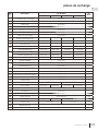
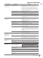
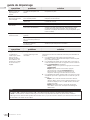
16.0 troubleshooting 90
17.0 warranty 93
The information throughout this manual is believed to be correct at the time of printing. Wolf Steel
Ltd. reserves the right to change or modify any information within this manual at any time without
notice. Changes, other than editorial are denoted by a vertical line in the margin.
note:

EN
W415-2035 / C / 04.30.21
5
general information
Installer: please fi ll out appliance checklist in the
owner’s manual.
When the appliance is installed at elevations above 4,500ft (1372m), and in the absence of specifi c recommendations
from the local authority having jurisdiction, the certifi ed high altitude input rating shall be reduced at the rate of 4% for each
additional 1,000ft (305m). Expansion / contraction noises during heating up and cooling down cycles are normal
and are to be expected. Change in fl ame appearance from “HI” to “LO” is more evident in natural gas than in
propane.
This appliance is approved for bathroom, bedroom and bed-sitting room installations and is certifi ed for mobile
home installation.
This appliance is only for use with the type of gas indicated on the rating plate. This appliance is not
convertible for use with other gases, unless a certifi ed kit is used.
There is a switch that controls the function of the appliance. The battery holder/switch must be placed in the
middle position. If the switch is not placed in the middle position, the appliance will not work.
The protective wrap on plated parts is best removed when the assembly is at room temperature but this can
be improved if the assembly is warmed, using a hair dryer or similar heat source. The protective wrap must be
removed before operating the appliance.
This appliance is a decorative product. It is not a source of heat and not intended to burn solid fuel.
This appliance is equipped with a remote control and a wall switch, which requires batteries to be installed. The
remote takes 3 “AAA” batteries and the wall switch takes 4 “AA” batteries.
note:
Batteries must be disposed of according to the local laws and regulations. Some batteries may be
recycled, and may be accepted for disposal at your local recycling center. Check with your
municipality for recycling instructions.
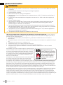
A glass guard assembly designed to reduce the risk of burns is provided with the appliance and must
be installed. Never operate the appliance without the complete Glass Guard Barrier System installed
and closed.
1.0 general information
important:
Some components and/or media are packaged separately and must be installed in accordance with the
information in this manual.

W415-2035 / C / 04.30.21
EN
6
general information
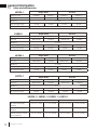
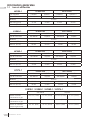
Single-Sided See-thru
Appliance Type LVX38N-1 LVX38P-1 LVX38N2-1 LVX38P2-1
Fuel Type Natural Gas Propane Natural Gas Propane
Altitude (FT) 0-4,500
Max. Input (BTU/HR) 31,000 26,500 31,000 26,500
Min. Input (BTU/HR) 22,000
Single-Sided See-thru
Appliance Type LVX50N-1 LVX50P-1 LVX50N2-1 LVX50P2-1
Fuel Type Natural Gas Propane Natural Gas Propane
Altitude (FT) 0-4,500
Max. Input (BTU/HR) 38,000 31,500 38,000 31,500
Min. Input (BTU/HR) 26,000 25,000 26,000 25,000
Single-Sided See-thru
Appliance Type LVX62N-1 LVX62P-1 LVX62N2-1 LVX62P2-1
Fuel Type Natural Gas Propane Natural Gas Propane
Altitude (FT) 0-4,500
Max. Input (BTU/HR) 44,000 35,000 44,000 35,000
Min. Input (BTU/HR) 32,000 28,000 32,000 28,000
LVX50-1
1.1 rates and effi ciencies
Single-Sided See-thru
Appliance Type LVX74N-1 LVX74P-1 LVX74N2-1 LVX74P2-1
Fuel Type Natural Gas Propane Natural Gas Propane
Altitude (FT) 0-4,500
Max. Input (BTU/HR) 50,000 41,500 50,000 41,500
Min. Input (BTU/HR) 35,000 33,0000 35,000 33,000
LVX38-1
LVX62-1
LVX74-1
Natural Gas Propane
Min. Inlet Gas Supply
Pressure
4.5" w.c. (11mb) 11" w.c. (27mb) 4.5" w.c. (11mb) 11" w.c. (27mb)
Max. Inlet Gas Supply
Pressure
7"* w.c. (17mb) 13” w.c. (32mb) 13” w.c. (32mb) 13” w.c. (32mb).
Manifold Pressure (Under
Flow Conditions)
3.5” w.c. (9mb) 10” w.c. (25mb) 3.5 w.c. (9mb) 10” w.c. (25mb)
LVX38-1 / LVX50-1 / LVX62-1 / LVX74-1
*Maximum inlet pressure not to exceed 13” w.c. (32mb).

EN
W415-2035 / C / 04.30.21
7
general information
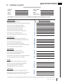
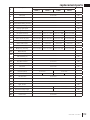
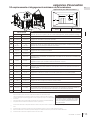
1.2 installation checklist
GAS FIREPLACE INSTALLATION CHECKLIST
Customer:
Date Installed:
Address: Installer:
Model: Dealer:
Serial #: Dealer Phone #:
This checklist is a reference tool only. It is not intended as a substitute for the installation instructions.
Wolf Steel Ltd. recommends photographs of the various stages of construction be filed along with a copy of this completed form.
Fireplace Installation
Is the fireplace level and secured?
YES IF NOT, PLEASE EXPLAIN WHY?
Are the factory supplied non-combustible materials installed?
Is the exterior wall insulated and dry-walled?
Are the clearances to combustibles maintained?
Are the logs/media installed as instructed?
Are the accessories installed as instructed?
Is the glass door properly sealed and unobstructed?
Is the safety barrier installed and secure?
Are all required accessories installed (i.e. door trims)?
Venting Installation
Is the venting configuration within the parameters?
Has the venting been sealed with the appropriate sealant?
Is the venting supported and secured?
Are all clearances to combustibles maintained?
Are the appropriate firestops and shields properly installed?
Is the terminal, level, secured and sealed?
Gas and Electrical
Was the fireplace converted to propane?
Was the appropriate supply pressure verified?
Were all gas connections leak tested?
Is the 110 VAC supply connection to the fireplace compliant?
Are all electrical wires protected from damage?
Finishing
Non-combustible materials used as per instructions?
Enclosure instructions forwarded to builder/finisher?
Minimum enclosure dimensions compliant?
Combustible Mantle Clearances compliant?
Commissioning
Was the fireplace test fired and all operation verified?
Safety and lighting instructions reviewed with the Customer?
Operating Instruction Manual left with the Customer?

W415-2035 / C / 04.30.21
EN
8
general information
general
information
14
10
13
6
5
8
9
4
3
2
GLASS GUARD
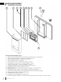
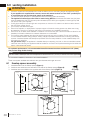
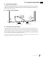
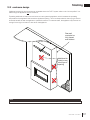
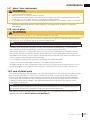
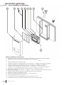
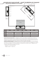
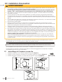
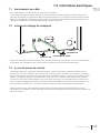
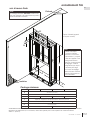
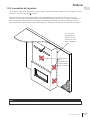
1.3 installation overview
Recommended installation steps:
1. Determine venting requirements before deciding the fi nal location of the appliance
2. Plan out appliance enclosure, framing, fronts, accessories, etc.
3. Install rough framing (refer to “rough framing” section)
4. Place the appliance in its fi nal position
5. Install nailing tabs (refer to “nailing tab installation” section)
6. Install appliance venting (refer to “venting installation” section)
7. Install vent shield (refer to “vent shield installation” section)
8. Install all electrical wirings (refer to “electrical information” section)
9. Install gas lines (refer to “gas installation” section)
10. Fit glass guard (refer to “glass guard assembly installation / removal” section)
11. Test appliance (Glass Guard must be installed while testing the appliance)
12. Remove and protect glass guard. Take great care to store using original packaging.
13. Complete framing (refer to “fi nish framing” section)
14. Finishing (refer to “fi nishing” section)
15. If necessary, do fi nal adjustments to glass guard.
16. Complete installation checklist in the owner’s manual and apply the serial number to owner’s manual

EN
W415-2035 / C / 04.30.21
9
general information
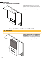
1.4 Dynamic Heat Control™
Dynamic Heat Control™ is a system for managing the
heat produced by the appliance at and around the fi re-
place. The purpose of the Dynamic Heat Control™ is
to move the heat away from the fi replace to allow it to cir-
culate more effectively within the living space. By install-
ing the Dynamic Heat Control™ both the installer and
the user gain considerable benefi ts, see the following;
Installer:
• Ability to use combustible framing and fi nishing right up to the fi replace opening.
*
• High temperatures above the front of the fi replace opening are signifi cantly reduced eliminating potential de-
grading to sensitive fi nish material (cracks or discoloration).
• No additional electricals, fans, ducts, or manifolds are required which keeps installation straightforward.
User:
• Heat is circulated more consistently throughout the living space increasing comfort in front of the fi replace.
• Increased “real world” effi ciency as heat is moved in to the room rather than retained inside an enclosure.
• Complete fl exibility in selection of fi nish materials.
• Ability to place a TV, sound bar or artwork above the fi replace.**
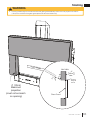
The Dynamic Heat Control™ system relies on an optimized fl ow of air both through the appliance and the en-
closure. As such the installation of the Dynamic Heat Control™ system requires certain technical considerations
when compared to traditional fi replaces. Specifi cally, the Dynamic Heat Control™ requires the enclosure to be
ventilated and requires the installer to ensure that a minimum opening area is provided to allow heat to escape
and circulate at a prescribed minimum height and position. This must be carefully adhered to in the planning and
the installation to ensure the appliance functions safely and to minimize installation time.
*In most common installation confi gurations, some specifi c installations require special provisions.
See “framing with Dynamic Heat Control™ section for details. Ensure to strictly adhere to instructions.
** Always check the appliance manufacturer’s recommendations to confi rm suitability and any special
environmental limitations. For valuable or antique items, always refer to expert preservation instruc-
tions as some items require specifi cally controlled temperature and/or humidity
PATENT PENDING

W415-2035 / C / 04.30.21
EN
10
general information
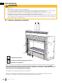
!
WARNING
• Always light the pilot whether for the fi rst time or if the gas supply has run out, with the glass door opened
or removed.
• Provide adequate clearance for servicing and operating the appliance.
• Provide adequate ventilation.
• Never obstruct the front opening of the appliance.
• Objects placed in front of the appliance must be kept a minimum of 48” (121.9cm) from the front face of
the appliance.
• Surfaces around and especially above the appliance can become hot. Avoid contact when appliance is
operating.
• Fire risk. Explosion hazard.
• High pressure will damage valve. Disconnect gas supply piping before pressure testing gas line at test
pressures above 1/2 PSIG. Close the manual shut-off valve before pressure testing gas line at test
pressures equal to or less than 1/2 PSIG (35mb).
• Use only Wolf Steel approved optional accessories and replacement parts with this appliance using non-
listed accessories (blowers, doors, louvres, trims, gas components, venting components, etc.) could result
in a safety hazard and will void the warranty and certifi cation.
• The appliance must not be operated at temperatures below freezing (32ºF / 0ºC). Allow the appliance to
warm to above freezing prior to operation.
• This appliance has been designed and certifi ed for indoor use only.
THIS GAS APPLIANCE MUST BE INSTALLED AND SERVICED BY A QUALIFIED INSTALLER to conform with local
codes. Installation practices vary from region to region and it is important to know the specifi cs that apply to your area, for
example in the state of Massachusetts:
• This product must be installed by a licensed plumber or gas fi tter when installed within the commonwealth of
Massachusetts.
• The appliance damper must be removed or welded in the open position prior to installation of an appliance insert or gas
log.
• The appliance off valve must be a “T” handle gas cock.
• The fl exible connector must not be longer than 36 inches (0.9m).
• A carbon monoxide detector is required in all rooms containing gas fi red appliances.
• The appliance is not approved for installation in a bedroom or bathroom unless the unit is a direct vent sealed
combustion product.
The installation must conform with local codes or, in absence of local
codes, the National Gas and Propane Installation Code CSA B149.1
in Canada, or the National Fuel Gas Code, ANSI Z223.1 / NFPA 54
in the United States. Suitable for mobile home installation if installed
in accordance with the current standard CAN/CSA Z240MH Series,
for gas equipped mobile homes, in Canada or ANSI Z223.1 and
NFPA 54 in the United States.
The appliance and its individual shutoff valve must be disconnected
from the gas supply piping system during any pressure testing
of that system at test pressures in excess of 1/2 psig (35 mb).
The appliance must be isolated from the gas supply piping system by closing its individual manual shutoff valve during any
pressure testing of the gas supply piping system at test pressures equal to or less than 1/2 psig (35 mb). When installed
with a blower or fan, the junction box must be electrically connected and grounded in accordance with local codes. In the
absence of local codes, use the current CSA C22.1 Canadian Electrical Code in Canada or the ANSI / NFPA 70 National
Electric Code in the United States. In the case where the blower is equipped with a power cord, it must be connected into a
properly grounded receptacle. The grounding prong must not be removed from the cord plug.
The following does not apply to inserts; as long as the required clearance to combustibles is maintained, the most desirable
and benefi cial location for an appliance is in the center of a building, thereby allowing the most effi cient use of the heat
created. The location of windows, doors and, the traffi c fl ow in the room where the appliance is to be located should be
considered. If possible, you should choose a location where the vent will pass through the house without cutting a fl oor or
roof joist. If the appliance is installed directly on carpeting, vinyl tile or other combustible material other than wood fl ooring, the
appliance shall be installed on a metal or wood panel extending the full width and depth, unless otherwise tested.
We suggest that our gas
hearth products be installed
and serviced by professionals
who are certied in the U.S.
by the National Fireplace
Institute
®
(NFI) as NFI Gas
Specialists
www.ncertied.org

EN
W415-2035 / C / 04.30.21
11
general information
CERTIFIED UNDER / HOMOLOGUE SELON LES NORMES: CSA 2.33
b
- 2008, ANSI Z21.88
b
- 2008 VENTED GAS FIREPLACE HEATER / APPAREIL DE CHAUFFAGE ALIMENTÉ
AU GAZ ET VENTILÉ
VENTED GAS FIREPLACE HEATER. APPROVED FOR BEDROOM, BATHROOM AND BED-SITTING ROOM INSTALLATION. SUITABLE FOR MOBILE HOME INSTALLATION IF INSTALLED IN ACCORDANCE WITH THE
CURRENT STANDARD CAN/CSA Z240MH SERIES GAS EQUIPPED MOBILE HOMES, IN CANADA OR IN THE UNITED STATES THE MANUFACTURED HOME CONST
RUCTION AND SAFETY STANDARD, TITLE 24 CFR,
PART 3280. WHEN THIS US STANDARD IS NOT APPLICABLE USE THE STANDARD FOR FIRE SAFETY CRITERIA FOR MANUFACTURED HOME INSTALLATION
S, SITES AND COMMUNITIES, ANSI / NFPA 501A.
FOYER DE CHAUFFAGE AU GAZ AVEC ÉVACUATION. HOMOLOGUÉ POUR INSTALLATION DANS UNE CHAMBRE À COUCHER, UNE SALLE DE BAIN ET UN STUD
IO. APPROPRIÉ POUR INSTALLATION DANS UNE
MAISON MOBILE SI SON INSTALLATION CONFORME AUX EXIGENCES DE LA NORME CAN/CSA Z240MH SÉRIE DE MAISONS MOBILES ÉQUIPÉES AU GAZ, E
N VIGUEUR AU CANADA OU AUX ÉTATS-UNIS DE LA
NORME DE SECURITÉ ET DE CONSTRUCTION DE MAISONS MANUFACTURÉES, TITRE 24 CFR, SECTION 3280. DANS LE CAS OU CETTE NORME D'ÉTATS-U
NIS NE PEUT ÊTRE APPLIQUÉE, SE RÉFÉRER A LA NORME
RELATIVE AU CRITÈRE DE MESURES DE SÉCURITÉ CONTRE L'INCENDIE POUR LES INSTALLATIONS DANS LES MAISONS MANUFACTURÉS, LES SITES ET
LES COMMUNAUTÉS, ANSI/NFPA 501A.
NOT FOR USE WITH
SOLID FUEL. FOR USE
WITH GLASS DOORS
CERTIFIED WITH THIS
UNIT ONLY.
WARNING
:
DO NOT ADD ANY MATERIAL
TO THE APPLIANCE, WHICH WILL COME
IN CONTACT WITH THE FLAMES, OTHER
THAN THAT SUPPLIED BY THE
MANUFACTURER WITH THE APPLIANCE.
MINIMUM CLEARANCE TO
COMBUSTIBLE MATERIALS:
TOP 0”
FLOOR 0”
RECESSED DEPTH ONE SIDED 23"
RECESSED DEPTH SEE THRU 13.5”
FRAMING (NOT INCLUDING
FACE MATERIAL)
SIDES 0”
VENT 2"
BACK 0”
MANTLE 15" *
TOP, SIDES & BACK: PER STAND OFF SPACERS FOR FRAMING MATERIALS. FOR FINISHING MATERIALS
SEE OWNERS MANUAL
UN COMBUSTIBLE SOLIDE NE
DOIT PAS ÊTRÉ UTILISÉ AVEC
CET APPAREIL. UTILISER AVEC
LES PORTES VITRÉES
HOMOLOGUÉES SEULEMENT
AVEC CETTE UNITÉ.
AVERTISSEMENT:
N'AJOUTEZ PAS A
CET APPAREIL AUCUN MATÉRIAU DEVANT
ENTRER EN CONTACT AVEC LES FLAMMES
AUTRE QUE CELUI QUI EST FOURNI AVEC
CET APPAREIL PAR LE FABRICANT.
DÉGAGEMENTS MINIMAUX DES
MATÉRIAUX COMBUSTIBLES:
DESSUS 0”
PROFONDEUR D'ENCASTRÉ 25"
PLANCHER 0”
ÉVENT 2"
CÔTES 0”
MANTEAU 15" *
ARRIÉRE 0”
MADE IN CANADA / FABRIQUÉ AU CANADA
WOLF STEEL LTD. BARRIE, ONTARIO, CANADA
ALTITUDE / ÉLÉVATION
INPUT / ALIMENTATION
REDUCED INPUT / ALIMENTATION RÉDUITE
ORIFICE / INJECTEUR
MANIFOLD PRESSURE /
PRESSION AU COLLECTEUR
MINIMUM SUPPLY PRESSURE /
PRESSION D'ALIMENTATION MINIMALE
MAXIMUM SUPPLY PRESSURE /
PRESSION D'ALIMENTATION MAXIMALE
0-4500FT (0-1370M)
30,000 BTU/H
23,000 BTU/H
#38
3.5" WATER COLUMN/D'UNE COLONNE D'EAU
4.5" WATER COLUMN/D'UNE COLONNE D'EAU
7.0" WATER COLUMN/D'UNE COLONNE D'EAU
0-4500FT (0-1370M)
30,000 BTU/H
23,000 BTU/H
#53
10" WATER COLUMN/D'UNE COLONNE D'EAU
11" WATER COLUMN/D'UNE COLONNE D'EAU
13" WATER COLUMN/ D'UNE COLONNE D'EAU
THE APPLIANCE MUST BE VENTED USING THE APPROPRIATE
NAPOLEON VENT KITS. SEE OWNERS INSTALLATION MANUAL
FOR VENTING SPECIFICS. PROPER REINSTALLATION AND
RESEALING IS NECESSARY AFTER SERVICING THE VENT-AIR
INTAKE SYSTEM.
L'APPAREIL DOIT ÉVACUER SES GAZ EN UTILISANT L'ENSEMBLE
D'ÉVACUATION PROPRE A NAPOLEON. RÉFÉRER AU MANUEL
D'INSTALLATION DE PROPRIÉTAIRE POUR L'ÉVACUATION
PRÉCISE. IL EST IMPORTANT DE BIEN RÉINSTALLER ET
RESCELLER L'ÉVENT APRÈS AVOIR ASSURÉ LE MAINTIEN DU
SYSTÉME DE PRISE D'AIR.
CLASSIFICATION: 115V 0.82AMP, 60HZ
W385-2007
MODEL NATURAL GAS /
GAZ NATURAL
LHD50NT
MODEL PROPANE
LHD50PT
SERIAL NUMBER/NO. DE SÉRIE:
LV50
ELECTRICAL RATING: 115V 0.82AMP, 60HZ
REFERENCE #
W/N 16131
* MAXIMUM HORIZONTAL EXTENSION / L'EXTENSION
HORIZONTALE MAXIMALE: 2". SEE INSTRUCTION MANUAL FOR GREATER EXTENSIONS.
SEE OWNER'S INSTRUCTION MANUAL FOR MINIMUM AND MAXIMUM VENT LENGTHS.
DESSUS, COTÉS & ARRIÈRE: SELON LES ESPACEURS DE DÉGAGEMENT POUR LES MATÉRIAUX D'OSSATURE
SELON LE MANUEL DE PROPRIÉTAIRE POUR LES MATÉRIAUX DE FINITION.
* L'EXTENSION HORIZONTALE MAXIMALE: 2". RÉFÉRER AU MANUEL D'INSTRUCTION POUR DES EXTENSIONS
PLUS GRANDES. RÉFÉRER AU MANUEL D'INSTALLATION DE PROPRIÉTAIRE.
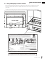
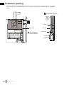
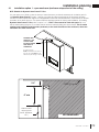
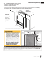
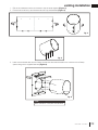
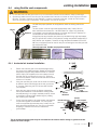
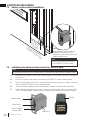
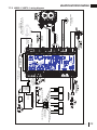
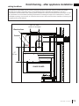
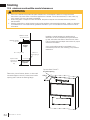
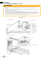
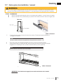
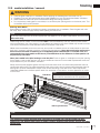
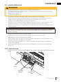
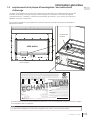
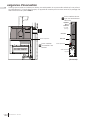
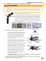
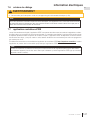
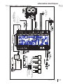
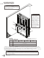
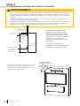
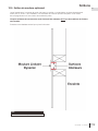
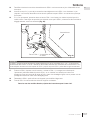
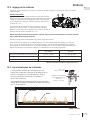
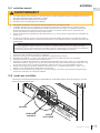
Both the rating plate and lighting instructions are attached to a chain located on the left side of the control
area near the valve (access side). Remove the glass guard and the control cover to gain access to the
control area.
To replace, slide the instructions back into the control area and slide the glass front into its locked position.
1.5 rating plate/lighting instruction location
This illustration is for reference only. Refer to the rating plate on the appliance for accurate information.
The rating plate must remain with the appliance at all times. It must not be removed.
note:
Pilot location
Rating plate
location
access side
Certified to Canadian and American National Standards: CSA 2.22-XXXX / ANSI Z21.50-XXXX for Vented Decorative Gas Appliances
Certifié selon les normes Nationales Canadiennes et Américaines: CSA 2.22-XXXX / ANSI Z21.50-XXXX pour les Appareils à gaz décoratif à évacuation
Direct vent, vented gas fireplaces. Approved for bedroom, bathroom and bed-sitting room installation. Suitable for mobile home installation, if installed in accordance with the current
standard CAN / CSA Z240MH Series gas equipped mobile homes in Canada, or, in the United States, the Manufactured Home Construction and Safety Standard, Title 24 CFR, Part
3280. When this US Standard is not applicable, use the Standard for Fire Safety Criteria for Manufactured Home Installations, Sites and Communities, ANSI / NFPA 501A. This appliance
must be installed in accordance with local codes, if any; if none, follow the current ANSI Z223.1 or CSA B149. For use with barrier WXXX-XXXX. Follow installation instructions.
Foyer à gaz ventilé. Homologué pour installation dans une chambre à coucher, une salle de bain et un studio. Approprié pour installation dans une maison mobile si son installation
conforme aux exigences de la norme CAN / CSA Z240MH Séries de maisons mobile équipées au gaz en vigueur au Canada, ou, aux États-Unis selon la norme 24 CFR, Part 3280,
Manufactured Home Construction and Safety Standard. Dans le cas ou cette norme d’États-Unis n’est pas pertinentes, utiliser la norme NFPA 501A, Fire Safety Criteria for Manufactured
Home Installations, Sites and Communities. Installer l’appareil selon les codes ou règlements locaux ou, en l’absence de tels règlements, selon les codes d’installation ANSI Z223.1 ou
CSA B149 en vigueur. Utiliser uniquement avec l’écran WXXX-XXXX. Suivre les instructions d’installation.
9700539 (WSL) 4001658 (NAC) 4001657 (NGZ) 4001659 (WUSA)
WOLF STEEL LTD. 24 Napoleon Road, Barrie, ON, L4M 0G8 Canada
XXXX XXXX XXXX XXXX
MODEL / MODÈLE
Altitude
Input
Reduced Input
P4
Élévation
Alimentation
Alimentation Réduite
P4
Manifold Pressure: 3.5” w.c. (NG)
Minimum Supply Pressure: 4.5” w.c. (NG)
Maximum Supply Pressure: 7”* w.c. (NG)
Pression au Collecteur: 3,5” d’une colonne d’eau (GN)
Pression d’Alimentation Min.: 4,5” d’une colonne d’eau (GN)
Pression d’Alimentation Max.: 7” ** d’une colonne d’eau (GN)
** Maximum inlet pressure not to exceed 13”.
Manifold Pressure: 10” w.c. (P)
Minimum Supply Pressure: 11” w.c. (P)
Maximum Supply Pressure: 13”* w.c. (P)
Pression au Collecteur: 10” d’une colonne d’eau (P)
Pression d’Alimentation Min.: 11” d’une colonne d’eau (P)
Pression d’Alimentation Max.: 13” * d’une colonne d’eau (P)
** Pression d’alimentation maximale ne devait pas dépasser 13”.
0-XXXXft (0-XXXXm)
Minimum clearance to combustible materials:
Top, sides & back: per standoff spacers for framing and finishing
materials. For non-combustible framing and finishing materials,
see installation manual.
Top X”
Floor X”
Sides X”
Back X”
Vent top X”
Vent sides & bottom X”
Recessed depth X”
*** Mantel X” from appliance opening
Dégagements minimaux des matériaux combustibles:
Dessus, côtés et arrière: selon les espaceurs de dégagements
pour les matériaux d’ossature selon le manuel du propriétaire
pour les matériaux de finition.
Dessus X”
Plancher X“
Côtés X”
Arrière X“
Dessus du conduit d’évent X”
Côtés et dessous du conduit d’évent X”
Profondeur d’encastré une face X”
*** Tablette X” de l’ouverture de l’appareil
WARNING: Do not add any material to the appliance which will come in contact with the
flames, other than that supplied by the manufacturer with the appliance.
AVERTISSEMENT: N’ajoutez pas à cet appareil aucun matériau devant entretien
contact avec les flammes autre que celui qui est fourni avec cet appareil par le fabricant.
*** Maximum horizontal extension:
X”. See installation manual for
greater extensions, minimum vent
lengths and maximum vent lengths.
*** L’extension horizontale maximale: X”.
Référez au manuel d’installation pour des
extensions plus grandes, les longueurs
d’évacuation minimaux et maximum.
The appliance must be vented using the appropriate Napoleon vent kits. See installation
manual for venting specifications. Proper reinstallation and resealing is necessary after servicing
the vent-air intake system.
L’appareil doit être ventilé à l’aide de l’ensemble d’évacuation propre à Napoleon. Référez au
manuel d’installation pour les spécifications d’évacuation. Il est nécessaire de bien réinstaller et
resceller l’évacuation après avoir executer l’entretien du système de prise d’air.
Serial Number / N° de Série:
W385-XXXX
REFERENCE# 161746
XXXX
VENTED DECORATIVE GAS APPLIANCE: NOT A SOURCE OF
HEAT, NOT INTENDED FOR USE AS A HEATING
APPLIANCE, NOT FOR USE WITH SOLID FUEL.
APPAREIL À GAZ DÉCORATIF À ÉVACUATION: N’EST PAS
UNE SOURCE DE CHALEUR; N’EST PAS DESTINÉ À ÈTRE
UTILISÉ COMME UN APPAREIL DE CHAUFFAGE; NE
CONVIENT PAS AUX COMBUSTIBLES SOLIDES.
FOR USE WITH GLASS DOORS CERTIFIED WITH THIS APPLIANCE ONLY.
POUR UTILISATION UNIQUEMENT AVEC LES PORTES EN VERRE
CERTIFIÉES AVEC L’APPAREIL.
XX,XXX XX,XXX
XX,XXX XX,XXX
For natural gas when equipped with No. XX drill size orifice.
For propane when equipped with No. XX drill size orifice.
Convient au gaz naturel quand l’appareil est muni d’un injecteur de diamètre no. XX.
Convient au propane quand l’appareil est muni d’un injecteur de diamètre no. XX.
Electrical rating: 115V, 60HZ. Less than 12 amperes.
Spécifications électriques: 115V, 60HZ. Moins de 12 ampère.
XX.X% XX.X%
XXXX XXXX XXXX XXXX

W415-2035 / C / 04.30.21
EN
12
general information
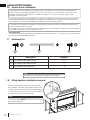
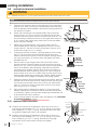
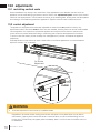
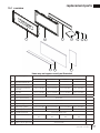
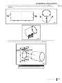
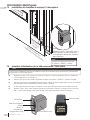
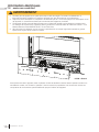
1.6 mobile home installation
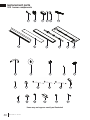
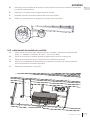
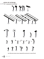
1.8 lifting handles installation/removal
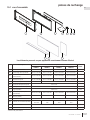
1.7 hardware list
1
2
3
Description Quantity
1
Hex Head Sheet Metal Screw 22
2
Pan Head Sheet Metal Screw 4
3
Hex Head Sheet Metal Bolt 18
This appliance must be installed in accordance with the manufacturer’s instructions and the Manufactured
Home Construction and Safety Standard, Title 24 CFR, Part 3280, in the United States or the Mobile Home
Standard, CAN/CSA Z240 MH Series, in Canada. This appliance is only for use with the type(s) of gas
indicated on the rating plate.
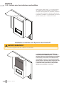
This mobile/manufactured home listed appliance comes factory equipped with a means to secure the appliance. The
shipping brackets that secure the appliance to the pallet can be used to secure the appliance to the fl oor for mobile
home installation. For mobile home installations, the appliance must be fastened in place.
This appliance is certifi ed to be installed in an aftermarket permanently located, manufactured (mobile) home,
where not prohibited by local codes.
This appliance is only for use with the type of gas indicated on the rating plate. This appliance is not convertible
for use with other gases, unless a certifi ed kit is used.
Conversion Kits
This appliance is fi eld convertible between Natural Gas (NG) and Propane (P). To convert from one gas to another,
consult your Authorized dealer/distributor.
note:
note:
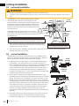
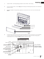
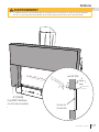
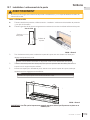
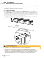
Only fasteners supplied with the appliance are illustrated.
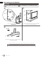
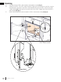
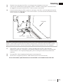
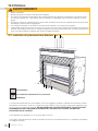
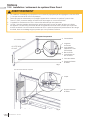
The lifting handles MUST be removed prior to rough
framing the appliance.
Remove 4 screws each side (8 total) then install the
lifting handles to the side of the appliance and secure
using 4 screws each side (8 total). Once the appliance
is in place remove the four screws from each handle to
the appliance. Discard the lifting handles.

EN
W415-2035 / C / 04.30.21
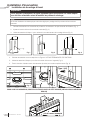
13
dimensions
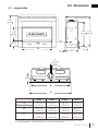
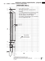
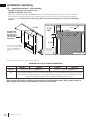
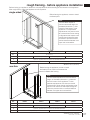
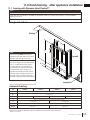
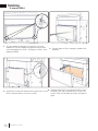
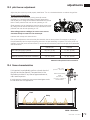
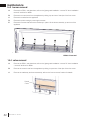
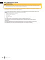
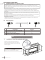
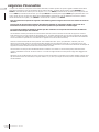
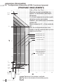
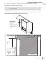
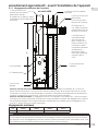
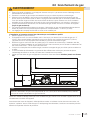
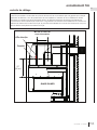
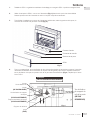
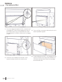
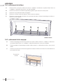
2.0 dimensions
2.1 single-sided
LVX38-1 LVX50-1 LVX62-1 LVX74-1
A
(Finishing Flange)
42 1/8”
(1070mm)
54 1/8”
(1375mm)
66 1/8”
(1680mm)
78 1/8”
(1984mm)
B
53 5/16”
(1354mm)
65 5/16”
(1659mm)
77 5/16”
(1964mm)
89 5/16”
(2269mm)
C
57 5/16”
(1456mm)
69 5/16”
(1761mm)
81 5/16”
(2065mm)
93 5/16”
(2370mm)
41 3/16"
1046mm
7 1/16"
179mm
18 5/8"
473mm
3 1/8"
80mm
17 3/16"
437mm
32 3/4"
832mm
39 11/16"
1008mm
8 1/16"
205mm
8 1/16"
205mm
Ø 8"
203mm
Ø 5"
127mm
GLASS GUARD
1/2"
[12.7mm]
A
B
C
*
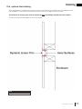
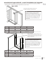
*Finishing flange depth (the finishing flange defines the perimeter of the fireplace opening. Framing
or finishing materials must NEVER encroach inside the finishing flange).
Base of air collar
17 11/16”
(449mm)

W415-2035 / C / 04.30.21
EN
14
dimensions
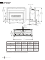
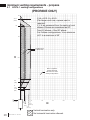
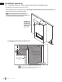
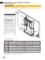
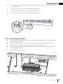
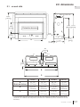
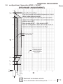
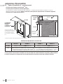
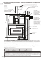
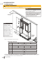
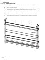
LVX38-1 LVX50-1 LVX62-1 LVX74-1
A
(Finishing Flange)
42 1/8”
(1070mm)
54 1/8”
(1375mm)
66 1/8”
(1680mm)
78 1/8”
(1984mm)
B
53 5/16”
(1354mm)
65 5/16”
(1659mm)
77 5/16”
(1964mm)
89 5/16”
(2269mm)
C
57 5/16”
(1456mm)
69 5/16”
(1761mm)
81 5/16”
(2065mm)
93 5/16”
(2370mm)
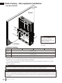
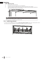
2.2 see-thru
41 3/16"
1046mm
7 1/16"
179mm
18 5/8"
473mm
3 1/8"
80mm
32 3/4"
832mm
39 11/16"
1008mm
16 3/16"
411mm
8 1/16"
205mm
8 1/16"
205mm
Ø 8"
203mm
Ø 5"
127mm
GLASS GUARD
1/2"
[12.7mm]
1/2"
[12.7mm]
A
B
C
*
*
Base of air collar
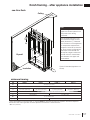
*Finishing flange depth (the finishing flange defines the perimeter of the fireplace opening. Framing or
finishing materials must NEVER encroach inside the finishing flange).

EN
W415-2035 / C / 04.30.21
15
minimum venting requirements
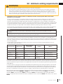
3.0 minimum venting requirements
!
WARNING
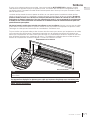
• Risk of fi re. Maintain specifi ed air space clearances to vent pipe and appliance.
• The vent system must be supported every 3’(0.9m) for both vertical and horizontal runs. Use support ring assembly
W010-0067 or equivalent non-combustible strapping to maintain the minimum clearance to combustibles for both
vertical and horizontal runs. Spacers are attached to the inner pipe at predetermined intervals to maintain an even air
gap to the outer pipe. This gap is required for safe operation. A spacer is required at the start, middle, and end of each
elbow to ensure this gap is maintained. These spaces must not be removed.
This appliance uses a 5” (127mm) exhaust / 8” (203.2mm) air intake vent pipe system. Refer to the section
applicable to your installation.
For safe and proper operation of the appliance follow the venting instructions exactly. Deviation from the minimum vertical
vent length can create diffi culty in burner start-up and/or carboning. Under extreme vent confi gurations, allow several
minutes (5-15) for the fl ame to stabilize after ignition. Although not a requirement, it is recommended for vent lengths that
pass through unheated spaces (attics, garages, crawl spaces) be insulated with the insulation wrapped in a protective sleeve
to minimize condensation. Provide a means for visually checking the vent connection to the appliance after the appliance is
installed. Use a fi restop, vent pipe shield or attic insulation shield when penetrating interior walls, fl oor or ceiling.
The vent terminal may be painted with a high temperature paint to match exterior colours. Use an outdoor paint suitable for
400°F (200°C). Application and performance of paint is the consumer’s responsibility. Spot testing is recommended.
Connections made by means of an adaptor at the appliance, as well as the connection at the vent terminal must be sealed.
RTV sealant may be used on both the inner exhaust and outer intake vent pipe joints of all other approved vent systems, ex-
cept for the exhaust vent pipe connection to the appliance fl ue collar which must be sealed using the black high temperature
sealant Mill Pac.
For all vent systems is strongly recommend for all installations but required when power venting the appliance, that the outer
air intake joints are sealed using either high temperature silicone (RTV) or a suitable aluminum tape that covers each joint in
the vent system entirely around its circumference. This will ensure the best performance in every application and avoids per-
formance or condensation concerns that may occur in “tightly” constructed homes, particularly those in cold climates.
Use only Wolf Steel, Metal-Fab, BDM, Simpson Dura-Vent, or Selkirk Direct Temp venting components. Minimum and
maximum vent lengths, for both horizontal and vertical installations, clearances from vent pipes to combustibles and air
terminal locations as set out in this manual apply to all vent systems and must be adhered to. For Metal-Fab, BDM, Simpson
Dura-Vent, or Selkirk Direct Temp, follow the installation procedure provided with the venting components or on the website
for your venting supplier.
A starter adaptor must be used with the following vent systems and may be purchased through Wolf Steel or from the
corresponding supplier listed below:
If for any reason the vent air intake system is disassembled; reinstall per the instructions provided for the initial
installation.
This appliance must be installed with a continuous connection of exhaust and air intake vent pipes. Utilizing alternate
constructions, such as a chimney as part of the vent system, is not permitted.
note:
Venting System Manufacturer
Starter Adapter
Part Number
Supplier Website
SureSeal Metal-Fab 5DNA Wolf Steel www.mtlfab.com
Direct Vent Pro Simpson DuraVent W175-0170 Wolf Steel www.duravent.com
Pro-Form BDM N/A BDM www.dalsinmfg.com
Direct Temp Selkirk 5DT-AAN Selkirk www.selkirkcorp.com
Ventis
Olympia Chimney
and Venting
VDV-NA05-58F
Olympia Chimney
and Venting
www.olympiachimney.com
When using Wolf Steel venting components, use only approved Wolf Steel rigid / fl exible components with the following
termination kits: wall terminal kit GD422R-2 or ST58U-1, or 1/12 to 7/12 pitch roof terminal kit GD410, 8/12 to 12/12 roof
terminal kit GD411, fl at roof terminal kit GD412 or periscope kit GD401 (for wall penetration below grade). With fl exible
venting, in conjunction with the various terminations, use either the 5 foot (1.5m) vent kit GD420 or the 10 foot (3.1m) vent kit
GD430.

W415-2035 / C / 04.30.21
EN
16
minimum venting requirements
For optimum fl ame appearance and appliance performance, keep the vent length and number of elbows to a minimum.
The air terminal must remain unobstructed at all times. Examine the air terminal at least once a year to verify that
it is unobstructed and undamaged.
Rigid and fl exible venting systems must not be combined. Different venting manufacturer components must not
be combined.
These vent kits allow for either horizontal or vertical venting of the appliance. The maximum allowable horizontal run is 20
feet (6.1m). The maximum allowable vertical vent length is 40 feet (12.2m). The maximum number of vent connections is two
horizontally or three vertically (excluding the appliance and the air terminal connections) when using fl exible venting.
Horizontal runs may have a 0” (0mm) rise per foot/meter however for optimum performance it is recommended that all
horizontal runs have a minimum 1/4” (21mm) rise per foot/meter using fl exible venting. For safe and proper operation of the
appliance, follow the venting instructions exactly.
A terminal shall not terminate directly above a sidewalk or paved driveway which is located between two single family dwell-
ings and serves both dwellings. Local codes or regulations may require different clearances.
Do not allow the inside liner to bunch up on horizontal or vertical runs and elbows. Keep it pulled tight. A 1¼” (31.8mm) air
gap all around between the inner liner and outer liner is required for safe operation.

EN
W415-2035 / C / 04.30.21
17
minimum venting requirements
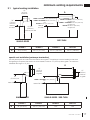
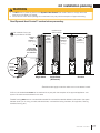
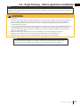
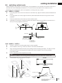
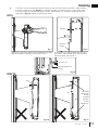
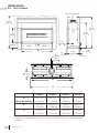
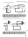
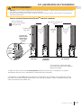
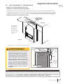
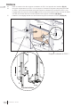
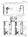
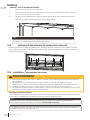
LVX38-1 LVX50-1 LVX62-1 LVX74-1
D
40” (101.6cm) 46 1/2” (118.1cm) N/A N/A
LVX38-1 LVX50-1 LVX62-1 LVX74-1
D
40” (101.6cm) 46 1/2” (118.1cm) 52 1/2” (133.4cm) 58 1/2” (148.6cm)
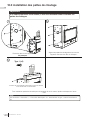
30”
(76.2cm)
LVX38-1 & LVX50-1: 30” (76.2cm) min
LVX62-1 & LVX74N-1: 48” (121.9cm)
min
LVX74P-1: 58” (147,3cm) min
LVX38-1 & LVX50-1: 62 3/4” (76.2cm)
min plus rise
LVX62-1 & LVX74N-1: 80 3/4” (205.1cm)
min plus rise
LVX74P-1: 90 3/4” (230.5cm)
min plus rise
62 3/4"
(159.4cm)
18"
(45.7cm)
SINGLE-SIDED
SINGLE-SIDED
SEE-THRU
SINGLE-SIDED / SEE-THRU
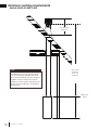
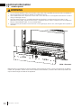
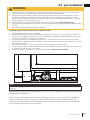
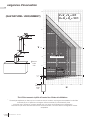
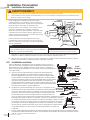
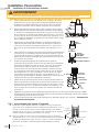
3.1 typical venting installation
minimum plus rise
maximum
minimum
base of
air collar
base of
air collar
D
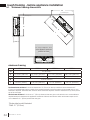
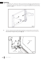
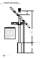
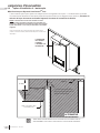
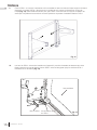
special vent installation (periscope termination)
Use the periscope kit to locate the air termination above grade. The periscope must be installed so that when
fi nal grading is completed, the bottom air slot is located a minimum 12” (30.5cm) above grade. The maximum
allowable vent length is 10’ (3m).
12"
(30.5cm)
minimum
to grade
30”
(76.2cm) min.
base of air collar
12"
(30.5cm)
minimum
to grade
D
base of air collar
LVX38-1 & LVX50-1: 30” (76.2cm)
min

W415-2035 / C / 04.30.21
EN
18
minimum venting requirements
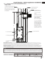
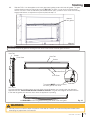
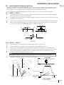
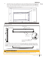
40 ft (12m)
maximum
6 ft (1m)
minimum
16" (40.6cm)
minimum
SINGLE-SIDED OR SEE-THRU
base of air
collar
A 6’ (1.83m) minimum vertical rise is
considered the minimum practical dimen-
sion for the specifi c appliance enclosure
and a minimal building structure. However,
a greater minimum vertical rise may be
needed to suit the specifi c application con-
straints or local codes and / or regulatory
requirements.
note:

EN
W415-2035 / C / 04.30.21
19
minimum venting requirements
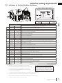
3.2 minimum air terminal location clearances
Q
MIN
R
MAX
MAX
R
= 3 feet
(0.9m)
= 2 x
IHHW
(4.6m)
Q
ACTUAL
INSTALLATIONS
CANADA U.S.A.
A
12” (30.5cm) 12” (30.5cm) Clearance above grade, veranda porch, deck or balcony.
B
12” (30.5cm)
Δ
9” (229mm)
Δ
Clearance to windows or doors that open.
C
12” (30.5cm)* 12” (30.5cm)* Clearance to permanently closed windows.
D
18”
(45.7cm)**
18”
(45.7cm)**
Vertical clearance to ventilated soffi ts located above the terminal within a horizontal distance of 2’ (0.6m)
from the center line of the terminal.
E
12” (30.5cm)** 12” (30.5cm)** Clearance to unventilated soffi t.
F
0” (0mm) 0” (0mm) Clearance to an outside corner wall.
G
0” (0mm)*** 0” (0mm)***
Clearance to an inside non-combustible corner wall or protruding non-combustible obstructions (chimney, etc.).
2” (51mm)*** 2” (51mm)*** Clearance to an inside combustible corner wall or protruding combustible obstructions (vent chase, etc.).
H
3’(0.9m) 3’(0.9m)****
Clearance to each side of the center line extended above the meter / regulator assembly to a maximum
vertical distance of 15’ (4.6m).
I
3’ (0.9m) 3’ (0.9m)**** Clearance to a service regulator vent outlet.
J
12” (30.5cm) 9” (229mm) Clearance to a non-mechanical air supply inlet to the building or a combustion air inlet to any other appliance.
K
6’ (1.8m) 3’ (0.9m) † Clearance to a mechanical air supply inlet.
L
7’ (2.1m) ‡ 7’ (2.1m) **** Clearance above a paved sidewalk or paved driveway located on public property.
M
12” (30.5cm)†† 12” (30.5cm)**** Clearance under a veranda, porch, deck or overhang.
N
16” (40.6cm) 16” (40.6cm) Clearance above the roof.
O
2’ (0.6m)†* 2’ (0.6m) †* Clearance from an adjacent wall including neighbouring buildings.
P
8’ (2.4m) 8’ (2.4m)
Roof must be non-combustible without openings.
Q
3’ (0.9m) 3’ (0.9m) See chart for wider wall dimensions.
R
6’ (1.8m) 6’ (1.8m)
See chart for deeper wall dimensions. The terminal shall not be installed on any wall that has an opening
between the terminal and the open side of the structure.
S
12” (30.5cm) 12” (30.5cm) Clearance under a covered balcony
Δ The terminal shall not be located less than 6 feet under a window that opens on a horizontal plane in a structure with three walls and a roof.
* Recommended to prevent condensation on windows and thermal breakage
** It is recommended to use a heat shield and to maximize the distance to vinyl clad soffi ts.
*** The periscope requires a minimum 18 inches clearance from an inside corner.
**** This is a recommended distance. For additional requirements, check local codes.
† 3 feet above if within 10 feet horizontally.
‡ A vent shall not terminate where it may cause hazardous frost or ice accumulations on adjacent property surfaces.
†† Permitted only if the veranda, porch, or deck is fully open on a minimum of two sides beneath the fl oor.
†* Recommended to prevent recirculation of exhaust products. For additional requirements, check local codes.
††* Permitted only if the balcony is fully open on a minimum of one side.
Wall terminals are for illustration purposes only. Size and shapes may vary. Wall terminal
measurements taken from the exhaust outlet, not the mounting plate.
Covered balcony applications ††*
R
Q
S
G
P
Clearances are to be in accordance with local
installation codes and the requirements of the gas
supplier. In their absence, clearances are to be as
listed above and are based on national codes.
note:
note:

W415-2035 / C / 04.30.21
EN
20
minimum venting requirements - natural gas
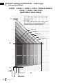
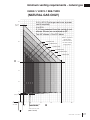
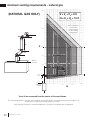
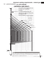
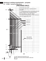
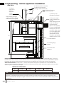
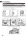
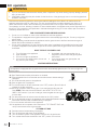
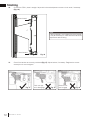
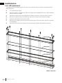
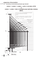
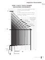
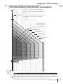
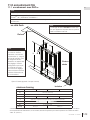
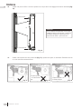
3.3 horizontal termination
0’
0’
Base of
air collar
10’
10’
15’
15’
20’
25’
20’
30’
40’
5’
3 7/8’ (46 1/2”) max.
(LV50-2 see-thru)
1 1/2’
(18”)
max.*
2 1/2’
(30”) min.*
38 1/2’
(462”)
5’
1 elbow zone
1-2 elbow zone
1-3 elbow zone
1-4 elbow zone
1-5 elbow zone
1-6 elbow zone
H
V
V+H ≤ 40 ft. (For longer vent runs, a power
vent is required).
H ≤ 20 ft.
V + H are measured from the centre of vent
elbows. Elbows are considered as 90º.
Two 45º elbows = One 90º elbow.
3 3/8’ (40”) max.
(LV38-1 see-thru)
LVX38-1 / LVX50-1 / LVX62-1 / LVX74-1 SINGLE-SIDED &
LVX38-1 / LVX50-1 SEE-THRU
(NATURAL GAS ONLY)
(LVX38-1 see-thru)
(LVX50-1 see-thru)
Page is loading ...
Page is loading ...
Page is loading ...
Page is loading ...
Page is loading ...
Page is loading ...
Page is loading ...
Page is loading ...
Page is loading ...
Page is loading ...
Page is loading ...
Page is loading ...
Page is loading ...
Page is loading ...
Page is loading ...
Page is loading ...
Page is loading ...
Page is loading ...
Page is loading ...
Page is loading ...
Page is loading ...
Page is loading ...
Page is loading ...
Page is loading ...
Page is loading ...
Page is loading ...
Page is loading ...
Page is loading ...
Page is loading ...
Page is loading ...
Page is loading ...
Page is loading ...
Page is loading ...
Page is loading ...
Page is loading ...
Page is loading ...
Page is loading ...
Page is loading ...
Page is loading ...
Page is loading ...
Page is loading ...
Page is loading ...
Page is loading ...
Page is loading ...
Page is loading ...
Page is loading ...
Page is loading ...
Page is loading ...
Page is loading ...
Page is loading ...
Page is loading ...
Page is loading ...
Page is loading ...
Page is loading ...
Page is loading ...
Page is loading ...
Page is loading ...
Page is loading ...
Page is loading ...
Page is loading ...
Page is loading ...
Page is loading ...
Page is loading ...
Page is loading ...
Page is loading ...
Page is loading ...
Page is loading ...
Page is loading ...
Page is loading ...
Page is loading ...
Page is loading ...
Page is loading ...
Page is loading ...
Page is loading ...
Page is loading ...
Page is loading ...
Page is loading ...
Page is loading ...
Page is loading ...
Page is loading ...
Page is loading ...
Page is loading ...
Page is loading ...
Page is loading ...
Page is loading ...
Page is loading ...
Page is loading ...
Page is loading ...
Page is loading ...
Page is loading ...
Page is loading ...
Page is loading ...
Page is loading ...
Page is loading ...
Page is loading ...
Page is loading ...
Page is loading ...
Page is loading ...
Page is loading ...
Page is loading ...
Page is loading ...
Page is loading ...
Page is loading ...
Page is loading ...
Page is loading ...
Page is loading ...
Page is loading ...
Page is loading ...
Page is loading ...
Page is loading ...
Page is loading ...
Page is loading ...
Page is loading ...
Page is loading ...
Page is loading ...
Page is loading ...
Page is loading ...
Page is loading ...
Page is loading ...
Page is loading ...
Page is loading ...
Page is loading ...
Page is loading ...
Page is loading ...
Page is loading ...
Page is loading ...
Page is loading ...
Page is loading ...
Page is loading ...
Page is loading ...
Page is loading ...
Page is loading ...
Page is loading ...
Page is loading ...
Page is loading ...
Page is loading ...
Page is loading ...
Page is loading ...
Page is loading ...
Page is loading ...
Page is loading ...
Page is loading ...
Page is loading ...
Page is loading ...
Page is loading ...
Page is loading ...
Page is loading ...
Page is loading ...
Page is loading ...
Page is loading ...
Page is loading ...
Page is loading ...
Page is loading ...
Page is loading ...
Page is loading ...
Page is loading ...
Page is loading ...
Page is loading ...
Page is loading ...
Page is loading ...
Page is loading ...
Page is loading ...
Page is loading ...
Page is loading ...
Page is loading ...
Page is loading ...
Page is loading ...
Page is loading ...
-
 1
1
-
 2
2
-
 3
3
-
 4
4
-
 5
5
-
 6
6
-
 7
7
-
 8
8
-
 9
9
-
 10
10
-
 11
11
-
 12
12
-
 13
13
-
 14
14
-
 15
15
-
 16
16
-
 17
17
-
 18
18
-
 19
19
-
 20
20
-
 21
21
-
 22
22
-
 23
23
-
 24
24
-
 25
25
-
 26
26
-
 27
27
-
 28
28
-
 29
29
-
 30
30
-
 31
31
-
 32
32
-
 33
33
-
 34
34
-
 35
35
-
 36
36
-
 37
37
-
 38
38
-
 39
39
-
 40
40
-
 41
41
-
 42
42
-
 43
43
-
 44
44
-
 45
45
-
 46
46
-
 47
47
-
 48
48
-
 49
49
-
 50
50
-
 51
51
-
 52
52
-
 53
53
-
 54
54
-
 55
55
-
 56
56
-
 57
57
-
 58
58
-
 59
59
-
 60
60
-
 61
61
-
 62
62
-
 63
63
-
 64
64
-
 65
65
-
 66
66
-
 67
67
-
 68
68
-
 69
69
-
 70
70
-
 71
71
-
 72
72
-
 73
73
-
 74
74
-
 75
75
-
 76
76
-
 77
77
-
 78
78
-
 79
79
-
 80
80
-
 81
81
-
 82
82
-
 83
83
-
 84
84
-
 85
85
-
 86
86
-
 87
87
-
 88
88
-
 89
89
-
 90
90
-
 91
91
-
 92
92
-
 93
93
-
 94
94
-
 95
95
-
 96
96
-
 97
97
-
 98
98
-
 99
99
-
 100
100
-
 101
101
-
 102
102
-
 103
103
-
 104
104
-
 105
105
-
 106
106
-
 107
107
-
 108
108
-
 109
109
-
 110
110
-
 111
111
-
 112
112
-
 113
113
-
 114
114
-
 115
115
-
 116
116
-
 117
117
-
 118
118
-
 119
119
-
 120
120
-
 121
121
-
 122
122
-
 123
123
-
 124
124
-
 125
125
-
 126
126
-
 127
127
-
 128
128
-
 129
129
-
 130
130
-
 131
131
-
 132
132
-
 133
133
-
 134
134
-
 135
135
-
 136
136
-
 137
137
-
 138
138
-
 139
139
-
 140
140
-
 141
141
-
 142
142
-
 143
143
-
 144
144
-
 145
145
-
 146
146
-
 147
147
-
 148
148
-
 149
149
-
 150
150
-
 151
151
-
 152
152
-
 153
153
-
 154
154
-
 155
155
-
 156
156
-
 157
157
-
 158
158
-
 159
159
-
 160
160
-
 161
161
-
 162
162
-
 163
163
-
 164
164
-
 165
165
-
 166
166
-
 167
167
-
 168
168
-
 169
169
-
 170
170
-
 171
171
-
 172
172
-
 173
173
-
 174
174
-
 175
175
-
 176
176
-
 177
177
-
 178
178
-
 179
179
-
 180
180
-
 181
181
-
 182
182
-
 183
183
-
 184
184
-
 185
185
-
 186
186
-
 187
187
-
 188
188


Ask a question and I''ll find the answer in the document
Finding information in a document is now easier with AI
in other languages
- français: NAPOLEON LVX38N2 Manuel utilisateur
Related papers
-
NAPOLEON BX42NTRE Vent Natural Gas Fireplace User manual
-
-
-
-
-
-
-
-
-
Other documents
-
Continental Fireplaces CB36NTR-1 User manual
-
-
-
-
-
-
-
-
Napoleon Fireplaces BGD42P User manual
-
Danby DDEF03813BD13 Owner's manual