Page is loading ...

Page 1 of 4
Installation and Operation Instructions
Dedicated Mtg Brackets
THIN SUPERVISOR For 2015-2020 Chevy Tahoe
IMPORTANT! Read all instructions before installing and using. Installer: This manual must be delivered to the end user.
WARNING!
Failure to install or use this product according to manufacturer’s recommendations may result in property damage, serious injury, and/
or death to those you are seeking to protect!
Do not install and/or operate this safety product unless you have read and understood the safety information
contained in this manual.
1. Proper installation combined with operator training in the use, care, and maintenance of emergency warning devices are essential to
ensure the safety of emergency personnel and the public.
2. Emergency warning devices often require high electrical voltages and/or currents. Exercise caution when working with live electrical
connections.
3. This product must be properly grounded. Inadequate grounding and/or shorting of electrical connections can cause high current arcing,
which can cause personal injury and/or severe vehicle damage, including re.
4. Proper placement and installation is vital to the performance of this warning device. Install this product so that output performance of
the system is maximized and the controls are placed within convenient reach of the operator so that they can operate the system without
losing eye contact with the roadway.
5. Do not install this product or route any wires in the deployment area of an air bag. Equipment mounted or located in an air bag
deployment area may reduce the eectiveness of the air bag or become a projectile that could cause serious personal injury or death.
Refer to the vehicle owner’s manual for the air bag deployment area. It is the responsibility of the user/operator to determine a suitable
mounting location ensuring the safety of all passengers inside the vehicle particularly avoiding areas of potential head impact.
6. It is the responsibility of the vehicle operator to ensure daily that all features of this product work correctly. In use, the vehicle operator
should ensure the projection of the warning signal is not blocked by vehicle components (i.e., open trunks or compartment doors),
people, vehicles or other obstructions.
7. The use of this or any other warning device does not ensure all drivers can or will observe or react to an emergency warning signal.
Never take the right-of-way for granted. It is the vehicle operator’s responsibility to be sure they can proceed safely before entering an
intersection, drive against trac, respond at a high rate of speed, or walk on or around trac lanes.
8. This equipment is intended for use by authorized personnel only. The user is responsible for understanding and obeying all laws
regarding emergency warning devices. Therefore, the user should check all applicable city, state, and federal laws and regulations. The
manufacturer assumes no liability for any loss resulting from the use of this warning device.
Installation and Mounting: Driver Side Shown
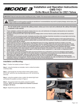
Step 1. Remove the plastic covers from the driver and passenger outer sun visor pivot brackets as shown in Figure 1. Remove the three (3)
Torx screws from each pivot bracket as shown in Figure 2. Pull the visor pivot brackets down from the headliner & carefully disconnect the
vehicle’s vanity mirror light wire connectors. Thread the screws all the way back into the plastic pivot bracket for easier assembly later.
Step 2. Pry open the small cover on the sun visor retaining clip with a small at bladed screwdriver to gain access to the sun visor retaining
clip screw (see Figure 3). Remove the single Torx screw that holds each clip in place as shown in Figure 4. Note: The plastic visor clips
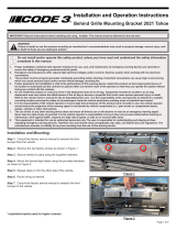
are held to the headliner fabric with stamped sheet metal clips that are located above the headliner fabric (See Figure 5). Carefully
pull & angle the plastic clips back and forth from side to side until the stamped sheet metal clips release the plastic clips from the headliner.
Remove the stamped clips and discard them so they don’t interfere with the Unit’s Installation or cause rattles after the installation. Thread
the Torx screw back into the plastic clip just slightly for easier assembly later.
Step 3. Position the inner visor clip brackets into the rectangular hole in the SuperVisor Inner Mounting Brackets as shown in Figure 6,
then position them up to the headliner. Push the plastic visor clip up into the rectangular hole in the headliner until you can feel it bottom out
against the vehicle’s inner sheet metal roof. Thread the small Torx screw back into the screw hole in the vehicle’s headliner (See Figure 7).
Leave the screws very loose so that you can position the Thin SuperVisor later.

Page 2 of 4
Figure 1 Figure 2
Figure 3 Figure 4
Installation and Mounting: Drivers Side Shown
Step 5. Position an Outer Mounting Bracket onto the plastic visor pivot bracket noting the dierence between the passenger and driver
side brackets (Driver Side is shown see Figure 8. Plug the vehicle’s vanity mirror light wire connectors back together, position the mounting
bracket up against the vehicle’s headliner & fasten the Mounting Bracket & the visor pivot bracket to the headliner by tightening the (3) Torx
screws as shown in Figure 9. Leave the screws very loose so that you can position the Thin SuperVisor.
Step 6. Position the Thin SuperVisor onto the mounting anges of the inner and outer mounting brackets making sure the upper gasket is
folded back correctly and locate the unit so that it is in position against the windshield. Thread the supplied 1/4”-20 screws and internal tooth
lock washers through the slots in the SuperVisor’s Inner and Outer Mounting Brackets and into the SuperVisor’s Outer Panel (See Figure 10
for proper locations of the screws).
Note: The passenger side screw positions are a mirror image of the driver side. Thread all of the 1/4”-20 screws so that they are up
against the mounting brackets but only nger tight and still loose enough to allow for adjustment of the units location.
Step 7. While alternately tightening the visor pivot bracket screws and inner clip bracket screws, continuously adjust the Thin SuperVisor unit
so that it stays in the optimal location in relation to the windshield. Continue tightening until the unit is snugly positioned and both gaskets are
touching the windshield. Do not over tighten the #8 screws. Tighten the 1/4”-20 screws.
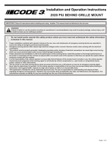
Step 8. Replace the plastic covers on the outer sun visor pivot brackets (see Figure 11). Also snap the plastic inner visor clip covers closed.
Plug the center cable from the driver side into the passenger side connector and route the Thin SuperVisor Cable as desired.

Page 3 of 4
Figure 5
Figure 6
Figure 7
Figure 8
Figure 9
Figure 10
Figure 11

Page 4 of 4
Product Returns:
If a product must be returned for repair or replacement*, please contact our factory to obtain a Return Goods Authorization Number (RGA
number) before you ship the product to Code 3®, Inc. Write the RGA number clearly on the package near the mailing label. Be sure you use
sucient packing materials to avoid damage to the product being returned while in transit.
*Code 3®, Inc. reserves the right to repair or replace at its discretion. Code 3®, Inc. assumes no responsibility or liability for expenses incurred for the removal and /or reinstallation of products requiring
service and/or repair.; nor for the packaging, handling, and shipping: nor for the handling of products returned to sender after the service has been rendered.
Manufacturer Limited Warranty Policy:
Manufacturer warrants that on the date of purchase this product will conform to Manufacturer’s specications for this product (which are avail-
able from the Manufacturer upon request). This Limited Warranty extends for Sixty (60) months from the date of purchase.
DAMAGE TO PARTS OR PRODUCTS RESULTING FROM TAMPERING, ACCIDENT, ABUSE, MISUSE, NEGLIGENCE, UNAPPROVED MODIFICA-
TIONS, FIRE OR OTHER HAZARD; IMPROPER INSTALLATION OR OPERATION; OR NOT BEING MAINTAINED IN ACCORDANCE WITH THE
MAINTENANCE PROCEDURES SET FORTH IN MANUFACTURER’S INSTALLATION AND OPERATING INSTRUCTIONS VOIDS THIS LIMITED WAR-
RANTY.
Exclusion of Other Warranties:
MANUFACTURER MAKES NO OTHER WARRANTIES, EXPRESS OR IMPLIED. THE IMPLIED WARRANTIES FOR MERCHANTABILITY, QUALITY
OR FITNESS FOR A PARTICULAR PURPOSE, OR ARISING FROM A COURSE OF DEALING, USAGE OR TRADE PRACTICE ARE HEREBY EX-
CLUDED AND SHALL NOT APPLY TO THE PRODUCT AND ARE HEREBY DISCLAIMED, EXCEPT TO THE EXTENT PROHIBITED BY APPLICABLE
LAW. ORAL STATEMENTS OR REPRESENTATIONS ABOUT THE PRODUCT DO NOT CONSTITUTE WARRANTIES.
Remedies and Limitation of Liability:
MANUFACTURER’S SOLE LIABILITY AND BUYER’S EXCLUSIVE REMEDY IN CONTRACT, TORT (INCLUDING NEGLIGENCE), OR UNDER ANY
OTHER THEORY AGAINST MANUFACTURER REGARDING THE PRODUCT AND ITS USE SHALL BE, AT MANUFACTURER’S DISCRETION, THE
REPLACEMENT OR REPAIR OF THE PRODUCT, OR THE REFUND OF THE PURCHASE PRICE PAID BY BUYER FOR NON-CONFORMING PROD-
UCT. IN NO EVENT SHALL MANUFACTURER’S LIABILITY ARISING OUT OF THIS LIMITED WARRANTY OR ANY OTHER CLAIM RELATED TO
THE MANUFACTURER’S PRODUCTS EXCEED THE AMOUNT PAID FOR THE PRODUCT BY BUYER AT THE TIME OF THE ORIGINAL PURCHASE.
IN NO EVENT SHALL MANUFACTURER BE LIABLE FOR LOST PROFITS, THE COST OF SUBSTITUTE EQUIPMENT OR LABOR, PROPERTY
DAMAGE, OR OTHER SPECIAL, CONSEQUENTIAL, OR INCIDENTAL DAMAGES BASED UPON ANY CLAIM FOR BREACH OF CONTRACT, IM-
PROPER INSTALLATION, NEGLIGENCE, OR OTHER CLAIM, EVEN IF MANUFACTURER OR A MANUFACTURER’S REPRESENTATIVE HAS BEEN
ADVISED OF THE POSSIBILITY OF SUCH DAMAGES. MANUFACTURER SHALL HAVE NO FURTHER OBLIGATION OR LIABILITY WITH RESPECT
TO THE PRODUCT OR ITS SALE, OPERATION AND USE, AND MANUFACTURER NEITHER ASSUMES NOR AUTHORIZES THE ASSUMPTION OF
ANY OTHER OBLIGATION OR LIABILITY IN CONNECTION WITH SUCH PRODUCT.
This Limited Warranty denes specic legal rights. You may have other legal rights which vary from jurisdiction to jurisdiction. Some jurisdic-
tions do not allow the exclusion or limitation of incidental or consequential damages.
© 2019 Code 3, Inc. all rights reserved.
920-0831-00 Rev. B
Warranty:
An ECCO SAFETY GROUP™ Brand
ECCOSAFETYGROUP.com
10986 North Warson Road, St. Louis, MO 63114 USA
Technical Service USA (314) 996-2800
CODE3ESG.com
/