Page is loading ...

SSAAFFEETTYY WWAARRNNIINNGG
Only qualified personnel should install and service the equipment. The installation, starting up, and servicing of heating, ventilating, and
air-conditioning equipment can be hazardous and requires specific knowledge and training. Improperly installed, adjusted or altered
equipment by an unqualified person could result in death or serious injury. When working on the equipment, observe all precautions in the
literature and on the tags, stickers, and labels that are attached to the equipment.
July 2019
1188--GGFF1100DD11--11CC--EENN
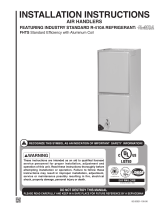
Wall Mount Air Handlers
2 – 3 Ton
AC models
GMU2APB24051SA
GMU2APB24081SA
GMU2APB30051SA
GMU2APB30081SA
GMU2AEB37051SA
GMU2AEB37101SA
HP models
GMV2APB26051SA
GMV2APB26081SA
GMV2APB32051SA
GMV2APB32081SA
GMV2AEB39051SA
GMV2AEB39101SA
The GMU and GMV series air handlers are designed for wall mount
or flush mount installations in a closet, utility room, alcove, or
basement. These versatile units are applicable to air conditioning
and heat pump applications. Several models are available to meet
the specific requirements of the outdoor equipment. Electric
resistance heaters are factory installed.
Installer’s Guide

©2018 Ingersoll Rand
18-GF10D1-1C-EN
SAFETY SECTION
AIR HANDLERS
IImmppoorrttaanntt:: This document contains a wiring diagram
and service information. This is customer
property and is to remain with this unit.
Please return to service information pack
upon completion of work.
IImmppoorrttaanntt:: These instructions do not cover all
variations in systems nor provide for every
possible contingency to be met in
connection with the installation. Should
further information be desired or should
particular problems arise which are not
covered sufficiently for the purchaser’s
purposes, the matter should be referred to
your installing dealer or local distributor.
WWAARRNNIINNGG
HHAAZZAARRDDOOUUSS VVOOLLTTAAGGEE!!
FFaaiilluurree ttoo ffoollllooww tthhiiss WWaarrnniinngg ccoouulldd rreessuulltt iinn
pprrooppeerrttyy ddaammaaggee,, sseevveerree ppeerrssoonnaall iinnjjuurryy,, oorr
ddeeaatthh..
DDiissccoonnnneecctt aallll eelleeccttrriicc ppoowweerr,, iinncclluuddiinngg rreemmoottee
ddiissccoonnnneeccttss bbeeffoorree sseerrvviicciinngg.. FFoollllooww pprrooppeerr
lloocckkoouutt//ttaaggoouutt pprroocceedduurreess ttoo eennssuurree tthhee ppoowweerr
ccaannnnoott bbee iinnaaddvveerrtteennttllyy eenneerrggiizzeedd..
CCAAUUTTIIOONN
GGRROOUUNNDDIINNGG RREEQQUUIIRREEDD!!
FFaaiilluurree ttoo iinnssppeecctt oorr uussee pprrooppeerr sseerrvviiccee ttoooollss mmaayy
rreessuulltt iinn eeqquuiippmmeenntt ddaammaaggee oorr ppeerrssoonnaall iinnjjuurryy..
RReeccoonnnneecctt aallll ggrroouunnddiinngg ddeevviicceess.. AAllll ppaarrttss ooff tthhiiss
pprroodduucctt tthhaatt aarree ccaappaabbllee ooff ccoonndduuccttiinngg eelleeccttrriiccaall
ccuurrrreenntt aarree ggrroouunnddeedd.. IIff ggrroouunnddiinngg wwiirreess,, ssccrreewwss,,
ssttrraappss,, cclliippss,, nnuuttss,, oorr wwaasshheerrss uusseedd ttoo ccoommpplleettee aa
ppaatthh ttoo ggrroouunndd aarree rreemmoovveedd ffoorr sseerrvviiccee,, tthheeyy mmuusstt
bbee rreettuurrnneedd ttoo tthheeiirr oorriiggiinnaall ppoossiittiioonn aanndd pprrooppeerrllyy
ffaasstteenneedd..
WWAARRNNIINNGG
LLIIVVEE EELLEECCTTRRIICCAALL CCOOMMPPOONNEENNTTSS!!
FFaaiilluurree ttoo ffoollllooww tthhiiss WWaarrnniinngg ccoouulldd rreessuulltt iinn
pprrooppeerrttyy ddaammaaggee,, sseevveerree ppeerrssoonnaall iinnjjuurryy,, oorr
ddeeaatthh..
FFoollllooww aallll eelleeccttrriiccaall ssaaffeettyy pprreeccaauuttiioonnss wwhheenn
eexxppoosseedd ttoo lliivvee eelleeccttrriiccaall ccoommppoonneennttss.. IItt mmaayy bbee
nneecceessssaarryy ttoo wwoorrkk wwiitthh lliivvee eelleeccttrriiccaall ccoommppoonneennttss
dduurriinngg iinnssttaallllaattiioonn,, tteessttiinngg,, sseerrvviicciinngg,, aanndd
ttrroouubblleesshhoooottiinngg ooff tthhiiss pprroodduucctt..
WWAARRNNIINNGG
PPRREESSSSUURRIIZZEEDD RREEFFRRIIGGEERRAANNTT!!
FFaaiilluurree ttoo ffoollllooww tthhiiss WWaarrnniinngg ccoouulldd rreessuulltt iinn
ppeerrssoonnaall iinnjjuurryy
SSyysstteemm ccoonnttaaiinnss ooiill aanndd rreeffrriiggeerraanntt uunnddeerr hhiigghh
pprreessssuurree.. RReeccoovveerr rreeffrriiggeerraanntt ttoo rreelliieevvee pprreessssuurree
bbeeffoorree ooppeenniinngg tthhee ssyysstteemm.. DDoo nnoo uussee nnoonn--
aapppprroovveedd rreeffrriiggeerraannttss oorr rreeffrriiggeerraanntt ssuubbssttiittuutteess oorr
rreeffrriiggeerraanntt aaddddiittiivveess..
CCAAUUTTIIOONN
SSHHAARRPP EEDDGGEE HHAAZZAARRDD!!
FFaaiilluurree ttoo ffoollllooww tthhiiss CCaauuttiioonn ccoouulldd rreessuulltt iinn
pprrooppeerrttyy ddaammaaggee oorr ppeerrssoonnaall iinnjjuurryy..
BBee ccaarreeffuull ooff sshhaarrpp eeddggeess oonn eeqquuiippmmeenntt oorr aannyy
ccuuttss mmaaddee oonn sshheeeett mmeettaall wwhhiillee iinnssttaalllliinngg oorr
sseerrvviicciinngg..
CCAAUUTTIIOONN
HHAAZZAARRDDOOUUSS VVAAPPOORRSS!!
FFaaiilluurree ttoo ffoollllooww tthhiiss ccaauuttiioonn ccoouulldd rreessuulltt iinn
pprrooppeerrttyy ddaammaaggee oorr ppeerrssoonnaall iinnjjuurryy..
EEqquuiippmmeenntt ccoorrrroossiioonn ddaammaaggee.. TToo pprreevveenntt
sshhoorrtteenniinngg iittss sseerrvviiccee lliiffee,, tthhee aaiirr hhaannddlleerr sshhoouulldd
nnoott bbee uusseedd dduurriinngg tthhee ffiinniisshhiinngg pphhaasseess ooff
ccoonnssttrruuccttiioonn oorr rreemmooddeelliinngg.. TThhee llooww rreettuurrnn aaiirr
tteemmppeerraattuurreess ccaann lleeaadd ttoo tthhee ffoorrmmaattiioonn ooff
ccoonnddeennssaattee.. CCoonnddeennssaattee iinn tthhee pprreesseennccee ooff
cchhlloorriiddeess aanndd fflluuoorriiddeess ffrroomm ppaaiinntt,, vvaarrnniisshh,, ssttaaiinnss,,
aaddhheessiivveess,, cclleeaanniinngg ccoommppoouunnddss,, aanndd cceemmeenntt
ccrreeaatteess aa ccoorrrroossiivvee ccoonnddiittiioonn wwhhiicchh mmaayy ccaauussee
rraappiidd ddeetteerriioorraattiioonn ooff tthhee ccaabbiinneett aanndd iinntteerrnnaall
ccoommppoonneennttss..
CCAAUUTTIIOONN
CCOOIILL IISS PPRREESSSSUURRIIZZEEDD!!
•• CCooiill iiss pprreessssuurriizzeedd wwiitthh aapppprrooxxiimmaatteellyy 88––1122 ppssii
ddrryy aaiirr aanndd ffaaccttoorryy cchheecckkeedd ffoorr lleeaakkss..
•• CCaarreeffuullllyy rreelleeaassee tthhee pprreessssuurree bbyy rreemmoovviinngg tthhee
rruubbbbeerr pplluugg oonn tthhee lliiqquuiidd lliinnee..
•• IIff nnoo pprreessssuurree iiss rreelleeaasseedd,, cchheecckk ffoorr lleeaakkss..
WWAARRNNIINNGG
WWAARRNNIINNGG!!
TThhiiss pprroodduucctt ccaann eexxppoossee yyoouu ttoo cchheemmiiccaallss
iinncclluuddiinngg lleeaadd,, wwhhiicchh aarree kknnoowwnn ttoo tthhee SSttaattee ooff
CCaalliiffoorrnniiaa ttoo ccaauussee ccaanncceerr aanndd bbiirrtthh ddeeffeeccttss oorr
ootthheerr rreepprroodduuccttiivvee hhaarrmm..
FFoorr mmoorree iinnffoorrmmaattiioonn ggoo ttoo wwwwww..PP6655WWaarrnniinnggss..ccaa..
ggoovv..

18-GF10D1-1C-EN
3
WWAARRNNIINNGG
SSAAFFEETTYY HHAAZZAARRDD!!
TThhiiss aapppplliiaannccee iiss nnoott ttoo bbee uusseedd bbyy ppeerrssoonnss
((iinncclluuddiinngg cchhiillddrreenn)) wwiitthh rreedduucceedd pphhyyssiiccaall,,
sseennssoorryy,, oorr mmeennttaall ccaappaabbiilliittiieess,, oorr llaacckk ooff
eexxppeerriieennccee aanndd kknnoowwlleeddggee,, uunnlleessss tthheeyy hhaavvee bbeeeenn
ggiivveenn ssuuppeerrvviissiioonn oorr iinnssttrruuccttiioonn..
WWAARRNNIINNGG
SSAAFFEETTYY HHAAZZAARRDD!!
CChhiillddrreenn sshhoouulldd bbee ssuuppeerrvviisseedd ttoo eennssuurree tthhaatt tthheeyy
ddoo nnoott ppllaayy wwiitthh tthhee aapppplliiaannccee..
WWAARRNNIINNGG
TThhiiss pprroodduucctt ccaann eexxppoossee yyoouu ttoo
cchheemmiiccaallss iinncclluuddiinngg lleeaadd,, wwhhiicchh aarree
kknnoowwnn ttoo tthhee SSttaattee ooff CCaalliiffoorrnniiaa ttoo
ccaauussee ccaanncceerr aanndd bbiirrtthh ddeeffeeccttss oorr
ootthheerr rreepprroodduuccttiivvee hhaarrmm.. FFoorr mmoorree
iinnffoorrmmaattiioonn ggoo ttoo wwwwww..PP6655WWaarrnniinnggss..
ccaa..ggoovv..!!
IImmppoorrttaanntt:: Installation of this unit shall be made in
accordance with the National Electric Code,
NFPA No. 90A and 90B, and any other local
codes or utilities requirements.
NNoottee:: The manufacturer recommends installing ONLY
A.H.R.I approved, matched indoor and outdoor
systems. Some of the benefits of installing
approved matched indoor and outdoor split
systems are maximum efficiency, optimum
performance, and the best overall system
reliability.
SSAAFFEETTYY SSEECCTTIIOONN AAIIRR HHAANNDDLLEERRSS

4
18-GF10D1-1C-EN
Installation . . . . . . . . . . . . . . . . . . . . . . . . . . . . . . . . . 5
Features . . . . . . . . . . . . . . . . . . . . . . . . . . . . . . . . . 5
Installation Instructions . . . . . . . . . . . . . . . . . . . 5
Field Wiring . . . . . . . . . . . . . . . . . . . . . . . . . . . . . . 9
Electrical Data . . . . . . . . . . . . . . . . . . . . . . . . . . . . . 10
Performance and Electrical Data . . . . . . . . . . . 13
Fixed Orifice Superheat Charging
Table . . . . . . . . . . . . . . . . . . . . . . . . . . . . . . . . . . . 16
Outline Drawing . . . . . . . . . . . . . . . . . . . . . . . . . . . 17
Blower Serviceability . . . . . . . . . . . . . . . . . . . . . . 18
Checkout Procedures . . . . . . . . . . . . . . . . . . . . 19
Table of Contents

18-GF10D1-1C-EN
5
Installation
Features
Table 1. Standard Features
• GALVANIZED STEEL EXTERIOR
• STURDY POLYCARBONATE DRAIN PAN
• 208/230 VAC OPERATION
• ECM MULTI-SPEED DIRECT DRIVE CTM BLOWER
(GMU2AEB37101SA and GMV2AEB39101SA only)
• MULTI-SPEED DIRECT DRIVE PSC BLOWER
• FACTORY SUPPLIED R-410A THERMAL EXPANSION VALVE
ON GMV MODELS
• ALL ALUMINUM COIL
• MEETS THE MINIMUM LEAKAGE REQUIREMENTS FOR THE
FLORIDA AND CALIFORNIA BUILDING CODES
• FRONT RETURN
• Factory installed 5, 8, and 10 KW SINGLE PHASE ELECTRIC
HEATERS
– Circuit breakers on all heaters
• SUPPLY DUCT FLANGES
Table 2. Optional Accessories
Use with all GMU2 and GMV2 models
• BAYTGM1WALLPNL — Wall Mount Panel Quantity 1
• BAYTGM5WALLPNL — Wall Mount Panel Quantity 5
Use with GMU2APB24 and GMV2APB26 models
• BAYFRT5LVPNL26A — Louver Panel Quantity 5
• BAYFRT1LVPNL26A — Louver Panel Quantity 1
Use with GMU2APB30, GMU2AEB37, GMV2APB32, GMV2AEB39
models
• BAYFRT5LVPNL30A — Louver Panel Quantity 5
• BAYFRT1LVPNL30A — Louver Panel Quantity 1
Table 3. Optional Orifice Kits
Outdoor Unit
Capacity (Tons)
Orifice Size
(R410A or R22)
Orifice Kit Number
1.5 0.049 BAYORIACH-
P0049A
2.0 0.057 BAYORIACH-
P0057A
2.5 0.061 BAYORIACH-
P0061A
3.0 0.067 BAYORIACH-
P0067A
Installation Instructions
1. UUnnppaacckkiinngg
Carefully unpack the unit and inspect the contents
for damage. If any damage is found at the time of
delivery, proper notification and claims should be
made with the carrier.
Check the rating plate to assure model number and
voltage, plus any kits match with what you ordered.
The manufacturer should be notified within 5 days
of any discrepancy or parts shortage.
2. GGeenneerraall AApppplliiccaattiioonnss
The GMV modelst can be used in an R22 application
by replacing the TXV with the correct size fixed
orifice piston.
The GMU models can be applied in either 410A or
R22 applications when the correct fixed orifice
piston is installed
3. LLooccaattiioonn
The air handler should be centrally located and can
be installed in a wall, closet, alcove, utility room, or
basement. Minimum clearances should be met.
When the unit is installed in a closet or utility room,
the room should be large enough, and have an
opening to allow replacement of the unit. All
servicing is done from the front and a clearance of
21" is needed for service unless the closet door or
wall panel aligns with the front of the air handler.
The air handler comes standard with two different
mounting options - wall mount or flush mount.
Both mounting options require that the unit be
installed level from side to side. Up to a 1/4” slope
towards the front is allowed. Both mounting
options also require that the mounting structure
have the ability to support a minimum load of
150lbs. Failure to do this will cause damage to the
support structure and potentially damage the unit.
WWaallll MMoouunntt IInnssttaallllaattiioonn
The air handler comes with a wall mounting bracket
for hanging the unit on a wall.
NNoottee:: Ensure bracket is installed on a structure that
can support a minimum load of 150 lbs. If
structure cannot support 150 lbs, additional
support may be needed.
1. Align holes of the bracket with wall studs or wall

6
18-GF10D1-1C-EN
structure. Ensure bracket is level. Install bracket
on the wall using the 4 provided wood screws.
2. Lift unit and slide the back edge of top cap onto
bracket.
FFlluusshh MMoouunntt IInnssttaallllaattiioonn
Optional
IImmppoorrttaanntt:: The unit should be installed flush with
the studs, not the sheetrock. This allows
clearance between the louvered panel
and the unit so the filter will not be
pressed up against the grill . It also
prevents the breaker switch from hitting
the panel.
The air handler comes with 4 clearance holes (2 on
each side) for mounting the unit flush between wall
studs or in a frame structure. NOTE: Ensure unit is
installed in a structure that can support a minimum
load of 150 lbs. Additional supports can be attached
to the studs to support the unit during installation.
See Figure.
NNoottee:: For ease of installation, optional two by fours
can be secured to the studs to support the
weight of the unit during installation.
1. Install the 4 provided wood screws into the
frame from within the air handler through the 2
clearance holes on each side of the unit.
Installing the screws from outside the unit could
cause damage to the coil.
2. Make sure unit is level and secure before
proceeding.
3. If using optional louvered panel which must be
ordered separately, install the louvered panel
per panel kit installation instructions.
4. DDuucctt WWoorrkk
The duct work should be installed in accordance
with the NFPA No. 90A "Installation of Air
Conditioning and Ventilating systems" and No. 90B
"Residential Type Warm Air Heating and Air
Conditioning Installation."
The duct work should be insulated in accordance
with the applicable requirements for the particular
installation as required by HUD, FHA, VA the
applicable building code, local utility or other
governing body.
5. FFrreesshh AAiirr
NNoottee:: This unit does not come with direct coupling
for fresh air.
NNoottee:: Do not tie into the air handler cabinet for
fresh air.
6. CCoonnddeennssaattee DDrraaiinn
This unit has 2 condensate drain options; front or
bottom. The unit comes from the factory ready for
front condensate connection. For bottom
condensate, remove the plugs from the bottom
drain connections and install them in the front drain
connections.
NNoottee:: Ensure that the unused location has the plugs
in place and are checked for leaks.
Each condensate drain option is supplied with
primary and auxiliary 3/4" NPT connections. The
primary drain must be trapped outside the unit and
piped in accordance with applicable building codes.
The figure shows the operation of a properly
designed trap under normal operating conditions.
Drain Pan
To Drain
Proper operation of condensate trap
under normal operating conditions.
Do not reduce the drain line size less than the
connection size on the drain pan. Condensate
should be piped to an open drain or to the outside.
All drains must pitch downward away from the unit
a minimum of 1/4" per foot of line to ensure proper
drainage.
IImmppoorrttaanntt:: If cleanout Tee is used, stand pipe must
be sealed/capped.
IImmppoorrttaanntt:: If a vent Tee is used, it must be
downstream from the trap.
IInnssttaallllaattiioonn

18-GF10D1-1C-EN
7
To Drain
Vent
-This vent pipe MUST
terminate above the
dotted line
Cleanout
(with Cap)
Cleanout
(Plug)
Insulate the primary drain line to prevent sweating
where dew point temperatures may be met.
(Insulation is optional depending on climate and
application needs.)
7. RReeffrriiggeerraanntt PPiippiinngg
Refrigerant piping external to the unit shall be sized
in accordance with the instructions of the
manufacturer of the outdoor equipment.
8. MMeetteerriinngg DDeevviiccee
GMV2 units are supplied with an internally-
checked, non-bleed TXV designed for air
conditioning or heat pump operation. Some
outdoor models may require a start assist kit.
GMU2 models include a factory installed orifice
piston. Piston size may need to be changed
depending on the equipment match. See outdoor
unit for more information.
Table 4. Included Metering Device
Air Handler Model Flow
Control
GMU2APB24 Orifice
GMU2APB30, GMU2AEB37
Orifice
GMV2APB26 TXV
GMV2APB32, GMV2AEB39 TXV
TTXXVV IInnssttaallllaattiioonn ffoorr HHeeaatt PPuummpp mmooddeellss
NNoottee:: Factory supplied O-rings must be used
between TXV fitting connections.
NNoottee:: Make sure to use a back—up wrench when
loosening or tightening fittings.
NNoottee:: This unit can be used in an R22 application
by replacing the TXV with the correct size
fixed orifice piston. See Table 5, p. 8 for
proper piston size.
GMV2 heat pump models require the supplied TXV
to be field installed. First, remove the stub tube
from the air handler liquid line. Braze the stub tube
to the field liquid line. Install the TXV and O-ring to
the liquid line fitting on the exterior of the cabinet.
Attach the inlet stub tube and O-ring to the TXV.
Attach the TXV sensing bulb to the field installed
vapor line outside of the unit using the supplied clip
to secure in place. Once installed, wrap the bulb
and clip with supplied insulation. Remove the
breaker panel to access the vapor line pressure
port. Route the TXV equalizer line with the 1/4” flare
nut down into the cabinet through the vapor line
cutout and connect to the pressure port on the
vapor line. The excess equalizer line must remain
outside of the cabinet.
NNoottee:: Ensure the valve core is removed for TXV
operation.
OOrriiffiiccee ppiissttoonn cchhaannggee oonn AACC mmooddeellss
Some GMU2 AC models require the orifice piston
to be replaced with a different size, which can be
purchased as individual kits from our parts
department (See Table 4). The orifice piston is
accessed by removing the front breaker panel. Use
a back—up wrench when disconnecting the fitting.
Remove the old piston using the wire tool supplied
with the kit. Install the new piston and tighten
fitting. Make sure to use a back—up wrench when
tightening fitting.
NNoottee:: The cabinet cover has been removed in the
illustration to show the interior component
detail. It should not be removed when
replacing the orifice piston.
NNoottee:: The wire tool pictured ships with the orifice
piston replacement kits.
NNoottee:: This unit can be applied in both 410A and R22
applications when the correct fixed orifice
piston is installed. See Table 5, p. 8.
IInnssttaallllaattiioonn

8
18-GF10D1-1C-EN
Table 5. Orifice Piston Size Table
Orifice Piston Size Table
Outdoor Unit
Capacity
(Tons)
Indoor Unit
Fixed Orifice
Piston Size
(a)
Indoor Unit Fixed Orifice
Replacement Part Kit
Number
1.5 0.049 BAYORIACHP0049A
2.0
0.057
(b)
BAYORIACHP0057A
2.5
0.061
(b)
BAYORIACHP0061A
3.0
0.067
(b)
BAYORIACHP0067A
(a)
Sizes are for both R-410A and R-22 refrigerants.
(b)
Factory installed in corresponding indoor units.
9. BBlloowweerr
This unit is supplied with a multi-speed motor with
a direct drive blower wheel which can obtain
various air flows. The unit is shipped with factory
set cooling and heating speed taps. Airflow
performance tables are available for additional
speed taps. Disconnect all power to the unit before
making any adjustments to the motor speed taps.
Be sure to check the temperature drop across the
evaporator coil to ensure sufficient air flow.
10. CCiirrccuuiitt BBrreeaakkeerr
Be sure to remove the tie wrap used to secure
circuit breaker during shipping. Ensure the circuit
breaker is correctly installed onto the circuit breaker
bracket.
11. WWiirriinngg
Consult all schematic and pictorial wiring diagrams
of this unit and the outdoor equipment to
determine compatibility of wiring connections and
to determine specific requirements.
All field wiring to the air handler should be installed
in accordance with the latest edition of the National
Electric Code NFPA No. 70 and any local codes.
Check rating plates on unit for rated volts,
minimum circuit ampacity and maximum over
current protection. Supply circuit power wiring
must be 75 degree C (167 degree F) minimum
copper conductors only. Copper supply wires shall
be sized to the National Electric Code or local code
requirements, whichever is more stringent.
The unit is shipped wired for 230/240 Volt AC 60 HZ
1 Phase Operation. If the unit is to be operated at
208 VAC 60HZ, follow the instructions on the indoor
unit wiring diagram to change the low voltage
transformer to 208 VAC operation (Ensure unit is
properly grounded).
Class 2 low voltage control wiring should not be run
in conduit with line voltage and must be separated
from line voltage unless class 1 wire with proper
voltage rating is used.
Low voltage control wiring should be 18 Awg, color
coded (105 degree C minimum). For lengths longer
than 100ft., 16 Awg wire should be used. Make
certain that separation of control wiring and line
voltage has been maintained.
12. TThheerrmmoossttaatt
Select a thermostat that is commonly used with HP
or AC single stage heating/cooling with electric
heat. The thermostat will energize the fan on a
demand for heat or cool.
Install the thermostat on an inside wall, away from
drafts, lights or other heat sources in a location that
has sufficient air circulation from other rooms being
controlled by the thermostat.
13. SSeeqquueennccee ooff OOppeerraattiioonn
CCoooolliinngg ((CCoooolliinngg oonnllyy))
PSC versions - When the thermostat calls for
cooling, the circuit from R to G is completed. The
blower relay is energized.
Constant torque version – When the thermostat
calls for cooling, the circuit from R to G is
completed. The blower motor is energized directly
by the 24VAC signal from the thermostat.
The circuit from R to Y is also complete energizing
the compressor contactor of the outdoor unit. The
contactor will close and start the compressor and
condenser fan motor.
CCoooolliinngg ((hheeaatt ppuummpp))
PSC versions - When the thermostat calls for
cooling, the circuit from R to G is completed. The
blower relay is energized.
Constant torque version – When the thermostat
calls for cooling, the circuit from R to G is
completed. The blower motor is energized directly
by the 24VAC signal from the thermostat.
The circuit from R to Y is also complete energizing
the compressor contactor of the outdoor unit. The
contactor will close and start the compressor and
condenser fan motor.
Circuit R to O energizes the reversing valve to the
cooling position.
HHeeaattiinngg ((hheeaatt ppuummpp))
PSC versions - When the thermostat calls for
heating, the circuit from R to G is completed. The
blower relay is energized.
Constant torque version – When the thermostat
calls for heating, the circuit from R to G is
completed and the blower motor is energized
directly by the 24VAC signal from the thermostat.
The circuit from R to Y is also complete energizing
the compressor contactor of the outdoor unit. The
contactor will close and start the compressor and
condenser fan motor.
In the heating mode, the reversing valve of the
outdoor unit is not energized.
If the indoor temperature continues to fall, the R to
IInnssttaallllaattiioonn

18-GF10D1-1C-EN
9
W circuit is completed energizing the electric heat
relays.
HHeeaattiinngg ((eelleeccttrriicc hheeaatt oonnllyy))
PSC versions - When the thermostat calls for
heating, the circuit from R to G is completed. The
blower relay is energized. The circuit from R to W is
completed energizing the heating contactor(s).
Constant torque version - When the thermostat
calls for heating, the circuit from R to G is
completed and the blower motor is energized
directly by the 24VAC signal from the thermostat.
The circuit from R to W is completed energizing the
heating contactor(s).
DDeeffrroosstt
Supplemental heat during defrost can be provided
by connecting the X2 (black) wire from the outdoor
unit to W1 at the indoor unit. This will prevent cold
air from being discharged from the indoor unit
during defrost.
14. OOppeerraattiioonnaall aanndd CChheecckkoouutt PPrroocceedduurreess
To obtain proper performance, all units must be
operated and charge adjustments made in
accordance with procedures found in the Service
Facts document of the outdoor unit. After
installation has been completed, it is recommended
that the entire system be checked against the
checkout list located at the back of this document.
See “Checkout Procedures,” p. 19
15. MMaaiinntteennaannccee
The system air filter(s) should be inspected, cleaned
or replaced at least monthly. Make certain that the
access panels are replaced and secured properly
before placing the unit back in operation. This
product is designed for dependable service;
however, periodic maintenance should be
scheduled and conducted by trained professional
service personnel. This service should be
conducted at least annually, and should include
testing and inspection of electrical and refrigerant
components. The heat transfer surface should be
inspected for cleanliness. The blower motor is
permanently lubricated for normal operating
conditions.
To protect the coil, blower and other internal parts
from excessive dirt and dust an air filter must be
installed before air enters the evaporator coil.
Consult the filter manufacturer for proper sizing and
maximum velocity requirements.
Field Wiring
R
G
B
W1
R
B
O
Y
X2
R
G
B/C
O
Y
W
HEAT PUMP SYSTEMS
Blue
24 VAC HOT
FAN
24 VAC
Common
SOV
COOL/HEAT
1st STAGE
HEATING
2nd STAGE
EMERGENCY
HEAT
Thermostat Air Handler
Outdoor
Unit
Black
White
White
X2
AC SYSTEMS
R
G
B
W1
B
Y
R
G
B/C
Y
W
Blue
24 VAC HOT
FAN
24 VAC
Common
COOLING
HEAT
Thermostat Air Handler
Outdoor
Unit
IInnssttaallllaattiioonn

10
18-GF10D1-1C-EN
Electrical Data
Figure 1. PSC Motor Wiring Diagram for GMU2APB24, GMU2APB30, GMV2APB26, and GMV2APB32
Figure 2. CTM Motor Wiring Diagram for GMU2AEB37 and GMV2AEB39


18-GF10D1-1C-EN
13
Performance and Electrical Data
GMU2APB24051SA, GMU2APB24081SA
External Static (in
w.g.)
Airflow
Speed Taps - 230 Volts Speed Taps - 208 Volts
High Med † Low High Med † Low
0.1 1005.7 784.1 615.3 898.4 670.7 520.9
0.2 950.2 763.7 597.6 869.2 661.1 503.7
0.3 895.4 729.2 558.1 826.9 636.3 466.6
0.4 776.7 629.4 466.0 715.7 550.9 382.2
0.5 594.2 464.5 321.3 535.6 405.0 250.6
0.6 347.8 234.4 286.7 198.5
Note:
1. Shaded boxes represent airflow outside the required 300-450 CFM/ton
2. Values are wet coil, no filter
3. CFM correction for dry coil = Add 3%
4. † = Factory default setting
Model No. Heater Model No.
Number of
Circuits /
Phases
Motor
Amps
Minimum Blower
Speed
240 Volt
Without
Heat
Pump
With Heat
Pump
Capacity
Heater
Amps per
Circuit
Minimum
Circuit
Ampacity
Maximum
Overload
Protection
kW BTUH
GMU2APB24051SA BAYHTRG605BRK
1/1
0.9 Low
N/A
4.8 16400 20 26 30
GMU2APB24081SA BAYHTRG608BRK
1/1
0.9 Low
N/A
7.68 26200 32 41 45
Model No. Heater Model No.
Number of
Circuits /
Phases
Motor
Amps
Minimum Blower
Speed
208 Volt
Without
Heat
Pump
With Heat
Pump
Capacity
Heater
Amps per
Circuit
Minimum
Circuit
Ampacity
Maximum
Overload
Protection
kW BTUH
GMU2APB24051SA BAYHTRG605BRK
1/1
0.9 Low
N/A
3.6 12300 17.3 23 25
GMU2APB24081SA BAYHTRG608BRK
1/1
0.9 Low
N/A
5.76 19700 27.7 36 40
GMV2APB26051SA, GMV2APB26081SA
External Static (in
w.g.)
Airflow
Speed Taps - 230 Volts Speed Taps - 208 Volts
High
Med † Low
High
Med † Low
0.1 1020.5 784.5 613.9 903.2 669.3 520.7
0.2 973.3 769.6 598.4 878.7 662.9 506.9
0.3 936.4 741.5 564.3 858.9 643.6 474.4
0.4 832.3 647.8 478.4 770.6 563.4 393.5
0.5 661.1 488.4 340.9 614.0 422.3 264.3
0.6 422.8 263.3 389.0 220.3
Note:
1. Shaded boxes represent airflow outside the required 300-450 CFM/ton
2. Values are wet coil, no filter
3. CFM correction for dry coil = Add 3%
4. † = Factory default setting

14
18-GF10D1-1C-EN
Model No. Heater Model No.
Number of
Circuits /
Phases
Motor
Amps
Minimum Blower
Speed
240 Volt
Without
Heat
Pump
With Heat
Pump
Capacity
Heater
Amps per
Circuit
Minimum
Circuit
Ampacity
Maximum
Overload
Protection
kW BTUH
GMV2APB26051SA BAYHTRG605BRK
1/1
0.9 Low Low 4.8 16400 20 26 30
GMV2APB26081SA BAYHTRG608BRK
1/1
0.9 Low Low 7.68 26200 32 43 45
Model No. Heater Model No.
Number of
Circuits /
Phases
Motor
Amps
Minimum Blower
Speed
208 Volt
Without
Heat
Pump
With Heat
Pump
Capacity
Heater
Amps per
Circuit
Minimum
Circuit
Ampacity
Maximum
Overload
Protection
kW BTUH
GMV2APB26051SA BAYHTRG605BRK
1/1
0.9 Low Low 3.6 12300 17.3 23 25
GMV2APB26081SA BAYHTRG608BRK
1/1
0.9 Low Low 5.76 19700 27.7 36 40
GMU2APB30081SA, GMU2APB30051SA
External Static (in
w.g.)
Airflow
Speed Taps - 230 Volts Speed Taps - 208 Volts
High Med † Low High Med † Low
0.1 1154.3 1086.0 1019.7 1139.6 1052.9 934.5
0.2 1091.6 1050.8 977.4 1073.2 1016.4 910.1
0.3 1037.4 996.2 932.2 1010.2 961.2 869.3
0.4 916.9 866.0 810.9 888.2 833.9 756.4
0.5 730.0 660.2 614.0 707.1 634.5 571.4
0.6 476.8 378.9 467.0 363.0
Note:
1. Shaded boxes represent airflow outside the required 300-450 CFM/ton
2. Values are wet coil, no filter
3. CFM correction for dry coil = Add 3%
4. † = Factory default setting
Model No. Heater Model No.
Number of
Circuits /
Phases
Motor
Amps
Minimum Blower
Speed
240 Volt
Without
Heat
Pump
With Heat
Pump
Capacity
Heater
Amps per
Circuit
Minimum
Circuit
Ampacity
Maximum
Overload
Protection
kW BTUH
GMU2APB30081SA BAYHTRG608BRK
1/1
2.20 Low
N/A
7.68 26200 32 43 45
GMU2APB30051SA BAYHTRG605BRK
1/1
2.20 Low
N/A
4.8 16400 20 28 30
Model No. Heater Model No.
Number of
Circuits /
Phases
Motor
Amps
Minimum Blower
Speed
208 Volt
Without
Heat
Pump
With Heat
Pump
Capacity
Heater
Amps per
Circuit
Minimum
Circuit
Ampacity
Maximum
Overload
Protection
kW BTUH
GMU2APB30081SA BAYHTRG608BRK
1/1
2.20 Low
N/A
5.76 19700 27.7 37 40
GMU2APB30051SA BAYHTRG605BRK
1/1
2.20 Low
N/A
3.6 12300 17.3 24 25
GMV2APB32081SA, GMV2APB32051A
External Static (in
w.g.)
Airflow
Speed Taps - 230 Volts Speed Taps - 208 Volts
High Med † Low High Med † Low
0.1 1164.9 1104.4 1018.9 1130.7 1062.5 942.1
0.2 1095.5 1048.2 962.9 1063.6 994.1 903.2
0.3 1020.2 997.0 906.1 993.6 923.2 857.6
0.4 877.6 871.1 782.5 855.1 790.7 744.4
0.5 667.7 670.7 591.9 648.1 596.5 563.6
PPeerrffoorrmmaannccee aanndd EElleeccttrriiccaall DDaattaa

18-GF10D1-1C-EN
15
0.6 390.3 395.7 372.5 340.6
Note:
1. Shaded boxes represent airflow outside the required 300-450 CFM/ton
2. Values are wet coil, no filter
3. CFM correction for dry coil = Add 3%
4. † = Factory default setting
Model No. Heater Model No.
Number of
Circuits /
Phases
Motor
Amps
Minimum Blower
Speed
240 Volt
Without
Heat
Pump
With Heat
Pump
Capacity
Heater
Amps per
Circuit
Minimum
Circuit
Ampacity
Maximum
Overload
Protection
kW BTUH
GMV2APB32081SA BAYHTRG608BRK
1/1
2.20 Low Low 7.68 26200 32 43 45
GMV2APB32051SA BAYHTRG605BRK
1/1
2.20 Low Low 4.8 16400 20 28 30
Model No. Heater Model No.
Number of
Circuits /
Phases
Motor
Amps
Minimum Blower
Speed
208 Volt
Without
Heat
Pump
With Heat
Pump
Capacity
Heater
Amps per
Circuit
Minimum
Circuit
Ampacity
Maximum
Overload
Protection
kW BTUH
GMV2APB32081SA BAYHTRG608BRK
1/1
2.20 Low Low 5.76 19700 27.7 37 40
GMV2APB32051SA BAYHTRG605BRK
1/1
2.20 Low Low 3.6 12300 17.3 24 25
GMU2AEB37101SA, GMU2AEB37051SA
External Static (in w.
g.)
Airflow
Speed Taps - 208–230 Volts
High Med-High † Med Med-Low Low
0.1 1129.5 1074.5 965.3 782.6 613.2
0.2 1107.0 1048.9 936.3 752.1 578.1
0.3 1084.0 1023.3 908.0 718.6 538.9
0.4 1060.3 997.8 880.5 692.2 495.7
0.5 1035.9 972.5 853.6 642.8 448.4
0.6 1011.0 947.1 827.4 600.4 697.1
0.7 985.5 921.9 802.0 555.1 341.7
Note:
1. Shaded boxes represent airflow outside the required 300-450 CFM/ton
2. Values are wet coil, no filter
3. CFM correction for dry coil = Add 3%
4. † = Factory default setting
Model No. Heater Model No.
Number of
Circuits /
Phases
Motor
Amps
Minimum Blower
Speed
240 Volt
Without
Heat
Pump
With Heat
Pump
Capacity
Heater
Amps per
Circuit
Minimum
Circuit
Ampacity
Maximum
Overload
Protection
kW BTUH
GMU2AEB37101SA BAYHTRG610BRK
1/1
2.90 Low
N/A
9.6 32800 40 54 60
GMU2AEB37051SA BAYHTRG605BRK
1/1
2.90 Low
N/A
4.8 16400 20 29 30
Model No. Heater Model No.
Number of
Circuits /
Phases
Motor
Amps
Minimum Blower
Speed
208 Volt
Without
Heat
Pump
With Heat
Pump
Capacity
Heater
Amps per
Circuit
Minimum
Circuit
Ampacity
Maximum
Overload
Protection
kW BTUH
GMU2AEB37101SA BAYHTRG610BRK
1/1
2.90 Low
N/A
7.2 24600 34.6 47 50
GMU2AEB37051SA BAYHTRG605BRK
1/1
2.90 Low
N/A
3.6 12300 17.3 25 25
GMV2AEB39101SA, GMV2AEB39051SA
External Static (in w.
g.)
Airflow
Speed Taps - 208–230 Volts
High Med-High † Med Med-Low Low
0.1 1110.7 1059.0 947.9 779.8 610.0
PPeerrffoorrmmaannccee aanndd EElleeccttrriiccaall DDaattaa

16
18-GF10D1-1C-EN
0.2 1085.2 1033.0 919.9 750.3 574.0
0.3 1059.7 1007.3 892.5 717.5 535.2
0.4 1034.1 981.8 865.6 681.6 493.7
0.5 1008.6 956.8 839.2 642.3 449.4
0.6 983.0 932.1 813.3 599.9 402.4
0.7 957.4 907.6 788.0 554.2 352.6
Note:
1. Shaded boxes represent airflow outside the required 300-450 CFM/ton
2. Values are wet coil, no filter
3. CFM correction for dry coil = Add 3%
4. † = Factory default setting
Model No. Heater Model No.
Number of
Circuits /
Phases
Motor
Amps
Minimum Blower
Speed
240 Volt
Without
Heat
Pump
With Heat
Pump
Capacity
Heater
Amps per
Circuit
Minimum
Circuit
Ampacity
Maximum
Overload
Protection
kW BTUH
GMV2AEB39101SA BAYHTRG610BRK
1/1
2.90 Low M-L 9.6 32800 40 54 60
GMV2AEB39051SA BAYHTRG605BRK
1/1
2.90 Low Low 4.8 16400 20 29 30
Model No. Heater Model No.
Number of
Circuits /
Phases
Motor
Amps
Minimum Blower
Speed
208 Volt
Without
Heat
Pump
With Heat
Pump
Capacity
Heater
Amps per
Circuit
Minimum
Circuit
Ampacity
Maximum
Overload
Protection
kW BTUH
GMV2AEB39101SA BAYHTRG610BRK
1/1
2.90 Low M-L 7.2 24600 34.6 47 50
GMV2AEB39051SA BAYHTRG605BRK
1/1
2.90 Low Low 3.6 12300 17.3 25 25
Fixed Orifice Superheat Charging Table
Indoor Wet Bulb Temp (F)
Outdoor Dry
Bulb
Temperature
(F)
50 51 52 53 54 55 56 57 58 59 60 61 62 63 64 65 66 67 68 69 70 71 72 73 74 75 76 77 78
55 7 9 10 11 12 14 15 17 18 20 21 23 24 26 27 29 30
60 5 7 8 9 10 12 13 15 16 18 19 21 22 24 25 27 28 30 31
65 4 6 8 10 11 13 14 16 17 18 19 21 22 24 25 27 28 27 31
70 5 7 8 10 11 13 14 16 17 18 19 21 22 24 25 27 28 30 31
75 5 6 7 9 10 12 14 16 18 19 21 22 24 26 28 29 31 32
80 4 6 7 9 10 11 12 14 16 18 19 21 23 25 26 28 29 31 33
85 4 6 7 9 10 13 14 16 18 20 21 23 24 26 28 29 30 31 32
90 4 6 8 10 11 13 14 16 18 20 22 24 25 27 28 30 31
95 4 6 8 10 13 14 16 18 20 22 23 25 26 28 29
100 6 8 10 12 13 16 18 20 21 23 25 27 29
105 4 6 7 9 11 13 15 18 20 22 24 26 28
110 4 7 9 11 13 16 18 21 23 26 28
115 6 9 12 14 16 19 21 24 26
Using a digital psychrometer, measure the return air wet-bulb temperature at the unit just before the coil. Also measure the outdoor dry-bulb
temperature. Use these temperatures to locate the target superheat on the charging table. Do not attempt to charge the system if these
conditions fall outside of this charging table.
ADD refrigerant to DECREASE total superheat. REMOVE refrigerant to INCREASE total superheat. Always allow 10 to 15 minutes of operation after
any refrigerant or air flow change prior to determining the final superheat.
PPeerrffoorrmmaannccee aanndd EElleeccttrriiccaall DDaattaa

18-GF10D1-1C-EN
17
Outline Drawing
Minimum Unit Clearance Table
Bottom View
Bottom condensate
drain locations
Front condensate
drain locations
To Combustible
Material (Required)
Service Clearance
(Recommended)
Sides 0” 0”
Front 0” 21”
Back 0” 0”
Outlet Duct &
Plenum
0” N/A
Condensate Piping
Below Cabinet
N/A 3”
TXV/Orice
Above Unit
N/A 9”
PRODUCT DIMENSIONS
Air Handler Model A B
Gas Line
Braze
Liquid Line
Braze
Filter Size
GMU2APB24 25.43 27.26
3/4 3/8
20 x 20 x 1
GMU2APB30, GMU2AEB37
29.43 31.26
3/4 3/8
20 x 24 x 1
GMV2APB26 25.43 27.26
3/4 3/8
(a)
20 x 20 x 1
GMV2APB32, GMV2AEB39
29.43 31.26
3/4 3/8
(a)
20 x 24 x 1
All dimensions are in inches
(a)
Includes a mechanical fitting with a 3/8” braze connection.

18
18-GF10D1-1C-EN
Blower Serviceability
1. Remove all power to the air handler.
2. Remove the top breaker panel by removing three
screws.
3. Remove the six screws shown in the illustration
that secure the coil in place.
4. Tilt the coil outward. Built-in stops will limit this to
40 degrees.
NNoottee:: When tilting the coil, the lineset does not
need to be disconnected. It is designed to
withstand coil tilting.
NNoottee:: The coil and drain pan can be cleaned with a
hose or sprayer when in the tilted position
without removal from the air handler.
5. Remove the circuit breaker bracket screws if a
circuit breaker is used.
NNoottee:: The circuit bracket assembly should hang out
of the way. The wires connected to the circuit
breaker do not need to be disconnected.
6. Disconnect the blower wiring.
IImmppoorrttaanntt:: Make sure to mark the wires with
connection points as they are removed
to be able to reconnect later.

18-GF10D1-1C-EN
19
7. Remove the two screws holding the blower in
place.
8. Tilt the front face of the blower downward to
release from the electric heat housing.
9. Lower the blower assembly to clear wiring and
obstructions. Maneuver the assembly over the
evaporator coil and out of the cabinet.
10. Perform service as needed to blower. Reassemble
the blower to the air handler following the steps in
reverse order.
Checkout Procedures
The final phase of the installation is the system Checkout Procedures. The following list represents the most common items covered in a
Checkout Procedure. Confirm all requirements in this document have been met.
☐ All wiring connections are tight and properly secured.
☐ Voltage and running current are within limits.
☐ All refrigerant lines (internal and external to equipment) are
isolated, secure, and not in direct contact with each other or
structure.
☐ All braze connections have been checked for leaks. A vacuum of
350 microns provides confirmation that the refrigeration system
is leak free and dry.
☐ Final unit inspection to confirm factory tubing has not shifted
during shipment. Adjust tubing if necessary so tubes do not rub
against each other or any component when unit runs.
☐ Ductwork is sealed and insulated.
☐ All drain lines are clear with joints properly sealed. Pour water into
drain pan to confirm proper drainage. Provide enough water to
ensure drain trap is primed.
☐ Supply registers and return grilles are open, unobstructed, and air
filter is installed.
☐ Indoor blower and outdoor fan are operating smoothly and
without obstruction.
☐ Indoor blower motor set on correct speed setting to deliver
required CFM. “Blower and fan set screws are tight.”
☐ Cover panels are in place and properly tightened.
☐ For gas heating systems, manifold pressure has been checked and
all gas line connections are tight and leak free.
☐ For gas heating systems, flue gas is properly vented.
☐ System functions safely and properly in all modes.
☐ Owner has been instructed on use of system and given manual.
BBlloowweerr SSeerrvviicceeaabbiilliittyy

Ingersoll Rand (NYSE: IR) advances the quality of life by creating comfortable, sustainable and efficient
environments. Our people and our family of brands — including Club Car
®
, Ingersoll Rand
®
, Thermo King
®
and
Trane
®
— work together to enhance the quality and comfort of air in homes and buildings; transport and protect
food and perishables; and increase industrial productivity and efficiency. We are a global business committed to a
world of sustainable progress and enduring results.
ingersollrand.com
Ingersoll Rand has a policy of continuous product and product data improvements and reserves the right to change design and specifications
without notice.
We are committed to using environmentally conscious print practices.
18-GF10D1-1C-EN 08 Jul 2019
Supersedes 18-GF10D1-1B-EN (October 2018) ©2018 Ingersoll Rand
/