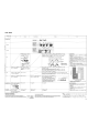
Hitachi RAM-90NP5B User manual
- Category
- Split-system air conditioners
- Type
- User manual
Hitachi RAM-90NP5B is a powerful and versatile air conditioner that can be used for cooling and heating purposes. It has a wide range of features that make it a great choice for any home or office.
Some of the key features of the Hitachi RAM-90NP5B include:
- Cooling and heating: The Hitachi RAM-90NP5B can be used to cool your home in the summer and heat it in the winter. This makes it a great choice for year-round comfort.
- Inverter technology: The Hitachi RAM-90NP5B uses inverter technology to adjust its cooling and heating output to match the needs of your home. This helps to save energy and money.


-
 1
1
-
 2
2
-
 3
3
-
 4
4
-
 5
5
-
 6
6
-
 7
7
-
 8
8
-
 9
9
-
 10
10
-
 11
11
-
 12
12
-
 13
13
-
 14
14
-
 15
15
-
 16
16
-
 17
17
-
 18
18
-
 19
19
-
 20
20
-
 21
21
-
 22
22
-
 23
23
-
 24
24
-
 25
25
-
 26
26
-
 27
27
-
 28
28
-
 29
29
-
 30
30
-
 31
31
-
 32
32
-
 33
33
-
 34
34
-
 35
35
-
 36
36
-
 37
37
-
 38
38
-
 39
39
-
 40
40
-
 41
41
-
 42
42
-
 43
43
-
 44
44
-
 45
45
-
 46
46
-
 47
47
-
 48
48
-
 49
49
-
 50
50
-
 51
51
-
 52
52
-
 53
53
-
 54
54
-
 55
55
-
 56
56
-
 57
57
-
 58
58
-
 59
59
-
 60
60
-
 61
61
-
 62
62
-
 63
63
-
 64
64
-
 65
65
-
 66
66
-
 67
67
-
 68
68
-
 69
69
-
 70
70
-
 71
71
-
 72
72
-
 73
73
-
 74
74
-
 75
75


Hitachi RAM-90NP5B User manual
- Category
- Split-system air conditioners
- Type
- User manual
Hitachi RAM-90NP5B is a powerful and versatile air conditioner that can be used for cooling and heating purposes. It has a wide range of features that make it a great choice for any home or office.
Some of the key features of the Hitachi RAM-90NP5B include:
- Cooling and heating: The Hitachi RAM-90NP5B can be used to cool your home in the summer and heat it in the winter. This makes it a great choice for year-round comfort.
- Inverter technology: The Hitachi RAM-90NP5B uses inverter technology to adjust its cooling and heating output to match the needs of your home. This helps to save energy and money.
Ask a question and I''ll find the answer in the document
Finding information in a document is now easier with AI
Related papers
-
Hitachi RAM-90QH5 User manual
-
-
-
Hitachi RAM-65QH4 User manual
-
-
-
Hitachi RAM-71QH5 User manual
-
-
-
Other documents
-
Haier AS26TACHRA User guide
-
-
Hisense HSA90R User manual
-
Dimplex DCES24 User manual
-
Airwell DCI 60 User manual
-
Kelvinator KSD25HRH User manual
-
Kelvinator KSD70HRG Installation guide
-
Panasonic ETHEREA CS-Z20TKEW Owner's manual
-
Friedrich VERT-I-PAK R410A User manual
-
Panasonic CU-E9PB4EA Owner's manual