
PEDESTAL
DRILL PRESS
450W
INSTRUCTION MANUAL
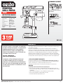
SPECIFICATIONS
Mains Voltage: 230–240V ~ 50Hz
Power: 300W (S1);
450W (S6 20%)
No Load Speed: 600 - 2,650/min
Chuck: Ø13mm Keyed
B16 Morse Taper
Chuck Size: Ø1.5 - 13mm
Max. Drilling Depth: 50mm
Table Tilt: 0-450 (Left & Right)
Weight: 13kg
BDP-450
STANDARD EQUIPMENT
3 YEAR REPLACEMENT WARRANTY*
Your product is guaranteed for a period of 36 months from the original date of purchase. If
a product is defective it will be replaced in accordance with the terms of this warranty. Warranty
excludes consumable parts, for example: valve adapters and accessories.
*This product is intended for DIY use only and replacement warranty covers domestic use.
WARNING
The following actions will result in the warranty being void.
• If the tool has been operated on a supply voltage other than that specified on the tool.
• If the tool shows signs of damage or defects caused by or resulting from abuse, accidents
or alterations.
• Failure to perform maintenance as set out within the instruction manual.
• If the tool is disassembled or tampered with in any way.
• Professional, industrial or high frequency use.
WARRANTY
Ozito Industries Pty. Ltd. 25 Fox Drive, Dandenong South, Victoria, Australia 3175.
ozito.com.au
Head Assembly, Table, Baseplate &
Main Column
Chuck Guard, Guard Arm, 3 x Feed
Wheel Handles & Belt Tension
Handle
Chuck, Chuck Key, 3 x Column Bolts
& 2 x Hex Keys
0622
IN ORDER TO MAKE A CLAIM UNDER THIS WARRANTY
YOU MUST RETURN THE PRODUCT TO YOUR NEAREST
BUNNINGS WAREHOUSE WITH YOUR BUNNINGS
REGISTER RECEIPT. PRIOR TO RETURNING YOUR
PRODUCT FOR WARRANTY PLEASE TELEPHONE OUR
CUSTOMER SERVICE HELPLINE:
Australia: 1800 069 486
New Zealand: 0508 069 486
The benefits provided under this warranty are in addition to other rights and remedies which
are available to you at law.
Our goods come with guarantees that cannot be excluded at law. You are entitled to a
replacement or refund for a major failure and for compensation for any other reasonably
foreseeable loss or damage. You are also entitled to have the goods repaired or replaced if the
goods fail to be of acceptable quality and the failure does not amount to a major failure.
Generally you will be responsible for all costs associated with a claim under this warranty,
however, where you have suffered any additional direct loss as a result of a defective product
you may be able to claim such expenses by contacting our customer service helpline above.
TO ENSURE A SPEEDY RESPONSE PLEASE HAVE
THE MODEL NUMBER AND DATE OF PURCHASE
AVAILABLE. A CUSTOMER SERVICE REPRESENTATIVE
WILL TAKE YOUR CALL AND ANSWER ANY QUESTIONS
YOU MAY HAVE RELATING TO THE WARRANTY POLICY
OR PROCEDURE.

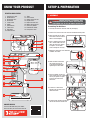
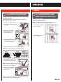
Assembling The Drill Press
1. Carefully remove the contents from the packaging.
2. Select a firm, level surface on which to assemble the drill press.
3. Align the holes on the base
of the main column with the
holes in the baseplate.
4. Place a washer onto each of
the 3 column bolts and use
these to fasten the column
into place; use an M10
wrench to tighten securely.
5. Rotate the table lever anti-clockwise
to loosen the collar.
6. Slide the table collar onto
the column and secure
at the desired position by
tightening the collar bolt.
7. Place the motor unit on the
main column and use a 4mm
hex key to tighten the grub
screw on the side of the
motor unit.
8. Screw the 3 feed wheel
handles into the slots on the
feed wheel hub.
9. Screw the belt tension handle into
the slot on the belt tension hub.
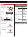
1. Belt Tension Lever
2. On/Off Switch
3. Guard Arm Lock
4. Guard Arm
5. Pulley Cover
6. Motor
7. Main Column
8. Table Lever
9. Baseplate
10. Table Tilt Bolt
11. Table
12. Chuck Guard
13. Guard Locking Screw
14. Keyed Chuck
15. Depth Indicator Lock
16. Motor Locking Screw
17. Chuck Key Holder
18. Feed Wheel Handle
19. Pulley Cover Lock
PEDESTAL DRILL PRESS
KNOW YOUR PRODUCT
1. ASSEMBLY
SETUP & PREPARATION
2
3
4
7
8
6
5
19
1
18
17
16
14
15
13
12
11
10
9
WARNING! ENSURE THE TOOL IS TURNED OFF AND
DISCONNECTED FROM THE POWER SUPPLY BEFORE
PERFORMING ANY OF THE FOLLOWING OPERATIONS.
ONLINE MANUAL
Scan this QR Code with your mobile
device to take you to the online manual.

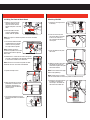
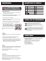
Installing The Chuck & Chuck Guard
1. With the chuck jaws fully
retracted into the chuck,
align the chuck with the
spindle and place it the drill
table.
2. Raise the table until the
chuck is approximately
25mm from the spindle.
Note: Use a piece of timber to protect the chuck and avoid
scratches.
3. Use the feed wheel handles
to slowly lower the spindle
until the chuck is pushed
securely onto the spindle.
Note: A gentle tap on the
timber is required to secure the
keyed chuck onto the tapered
drive shaft
4. Remove the 2 screws on the side of the guard
arm with a screwdriver (not supplied) and slide
it into the arm holder on the motor unit.
Note: Ensure the 2 screws and guard arm lock
knob will face the user when reassembled.
5. Tighten the stop screw.
6. Align the holes on the chuck
guard with the holes on the
guard arm and refit the 2
removed screws to hold the
guard in place.
7. Use the guard locking screw to
lock the guard arm in the desired
position.
Attaching A Drill Bit
1. Swing the chuck guard out
of the way.
2. Push the chuck key into
any of the holes in the side
of the chuck and turn it
anti-clockwise to loosen the
chuck jaws.
3. Insert the drill bit fully into
the chuck.
4. Hold the drill bit in one hand
and rotate the chuck key
clockwise to tighten the jaws
around the drill bit.
Note: Ensure drill bit is straight
before fully tightening.
Note: Tighten the chuck jaws
from all 3 holes with the chuck key fasten the drill bit securely.
5. Swing the chuck guard back
into place and store the
chuck key in the holder on
the side of the motor unit.
25mm
a.
b.

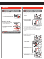
Adjusting The Table Height
1. Loosen the collar bolt.
2. Set the table to the desired height, then
use the lever to tighten the table collar.
Adjusting The Table Angle
1. Use the supplied hex key to loosen
the screw under the table.
2. Set the table to the desired angle
and retighten the screw to lock the
table in place.
WARNING! ENSURE THE WORKPIECE IS CLAMPED TO
THE TABLE WHEN THE TABLE IS ANGLED/TILTED.
Stopping The Bit & Spindle At A Preset Depth
1. Loosen the depth indicator locks
by turning in an anti-clockwise
direction.
2. Rotate the depth indicator
ring to the desired depth,
then tighten the locks.
3. Proceed to drill as normal. The depth lock will stop the drill
when the required drilling depth is reached.
4. To disable the preset depth function, loosen the indicator lock
and set the indicator ring to the maximum drilling capacity
(50mm).
Holding The Bit At A Desired Depth
1. Loosen the depth locks.
2. Turn the feed wheel handle
to lowest position.
3. Rotate the indicator ring to
the desired depth.
4. Tighten the depth locks. This will
hold the bit and spindle stationary at
the desired depth.
2. ADJUSTMENTS
0
10
20
30
40
50
0
10
20
30
40
50
50
40
30
20
50
40
30
20
b.
a.
WARNING! ENSURE THE TOOL IS TURNED OFF AND
DISCONNECTED FROM THE POWER SUPPLY BEFORE
PERFORMING ANY OF THE FOLLOWING OPERATIONS.
WARNING! ENSURE THE TOOL IS TURNED OFF AND
DISCONNECTED FROM THE POWER SUPPLY BEFORE
PERFORMING ANY OF THE FOLLOWING OPERATIONS.

Changing The Speed
The speed of the drill press can be adjusted by changing the
position of the belt on the pulleys.
1. Lower the chuck down to ensure it
is not in the way when opening the
pulley cover.
2. Loosen the cover bolt and
motor locking screw, then
open the pulley cover.
3. T urn the belt tension lever clockwise
to move the motor head inwards
and slacken the drive belt.
4. Adjust the belt position to the desired speed setting.
Note: Refer to the pulley table for corresponding speeds.
4. Turn the belt tension lever anti-
clockwise to re-tension the belt.
Note: The tension is properly set when
the belt only moves approximately 1cm
when you press on the middle of it.
5. Close the cover and retighten
the cover bolt and motor
locking screw.
Note: The safety switch will prevent the drill press from starting up
if the pulley cover is not fully closed properly.
Switching The Tool On & Off.
Note: Ensure that the pulley cover is fully closed otherwise the
safety cut-off will prevent the tool from starting up.
1. Press the green (I) button to
start the drill press.
2. Press the red (0) button to
stop the drill press.
3. CONTROLS
OPERATION
0
I
0
I
SPEED 1 [ 600/min ]
SPEED 2 [ 900/min ]
SPEED 3 [ 1,300/min ]
SPEED 4 [ 1,800/min ]
SPEED 5 [ 2,650/min ]
CHUCK MOTOR IN TIMBER
1.5-10mm
13mm
-
-
-
IN SOFT METAL
1.5-5mm
6-8mm
10mm
13mm
-
DRILL BIT DIAMETER
8-10mm
IN HARD METAL
1.5mm
3mm
5-6mm
13mm
WARNING! ENSURE THE TOOL IS TURNED OFF AND
DISCONNECTED FROM THE POWER SUPPLY BEFORE
PERFORMING ANY OF THE FOLLOWING OPERATIONS.
WARNING! THE POWER SUPPLY FOR THE DRILL
PRESS SHOULD BE PROTECTED BY A RESIDUAL
CURRENT DEVICE (RATED AT 30mA OR LESS). A
RESIDUAL CURRENT DEVICE REDUCES THE RISK OF
ELECTRIC SHOCK.
BDP-450

5. TROUBLESHOOTING
Symptom Possible Cause Suggested Solution
Drill press will
not start
Pulley cover not
secured
Check the pulley cover
is closed and lowered
correctly in position
Power cord not
connected to the mains
power supply
Ensure that the power
cord is connected to
the mains power
Power fault Check the mains
power supply
Power cord damage Use an authorised
service centre to
repair or replace
Faulty switch or motor Use an authorised
service centre to
repair or replace
Noisy
operation
Incorrect belt tension Adjust tension as
required
Drill bit burns Drill bit is dull Use a new drill bit or
re-sharpen drill bit
Not lubricated Lubricate drill bit
Excessive drill
bit wobble
Bent or damaged drill
bit
Use a new drill bit
Drill bit is not securely
placed in the keyed
chuck
Remove the drill bit
and reinsert correctly,
ensure the chuck jaws
are fully tightened
The keyed chuck is not
installed correctly
Ensure you install the
keyed chuck correctly
Drill bit binds
in workpiece
Belt tension is set
incorrectly
Re-adjust the belt
tension
Using The Drill Press
1. Select and set your required drilling depth.
2. Adjust the table to the
desired height and angle.
3. Ensure the
workpiece is
clamped securely to
the table.
Note: Place a scrap piece of timber under the workpiece if drilling
through for a neater finish.
Note: With the tool off, you can lower the drill bit until the tip
touches the workpiece to align the workpiece correctly before
clamping it in place.
4. Switch the unit on and
slowly lower the drill by
rotating the feed wheel.
5. Once finished drilling, slowly release the feed wheel to return
the chuck to it’s original position.
6. Press the red (0) button to
switch the drill press off.
Note: When drilling metal, it is necessary to lubricate the tip of the
drill bit with oil to prevent it from overheating.
4. USAGE
0
I
0
I
0
10
20
30
40
50
SCRAP
MATERIAL

MAINTENANCE DESCRIPTION OF SYMBOLS
General Maintenance
1. Ball bearings are packed with grease at the factory. No further
lubrication of bearings is required.
2. Lubricate all moving parts periodically. Wipe the column, table
and base with an oily cloth to minimise corrosion.
3. Keep air vents clean of dust and dirt.
4. Remove dust and dirt from the drill press regularly with a soft
cloth, brush or compressed air.
5. Regularly check that all bolts, screws and nuts are securely
fixed as these could work loose during normal operation.
6. If the drive belt will not align with the
pulleys. The pulleys may be worn and
need to be replaced. To remove the
pulleys, use the 3mm hex key provided.
Loosen in an anti-clockwise direction.
Note: Grub screw should not be sticking
out.
Cleaning
1. We recommend that you clean the appliance immediately after
you use it.
2. Keep the safety devices free of dirt and dust as much as
possible. Wipe the equipment with a clean cloth.
3. Clean the appliance regularly with a damp cloth and some soft
soap. Do not use cleaning agents or solvents; these may be
aggressive to the plastic parts in the appliance. Ensure that no
water can get into the interior of the appliance.
Storage
Pull the mains plug out of the socket, switch off the tool and make
sure that it is secured in such a way that it cannot be started up
again by any unauthorised person.
Store the tool in a dry location which is not accessible to
unauthorised persons.
Supply Cords
If replacement of the supply cord is necessary, this has to be done
by a certified electrician in order to avoid a safety hazard.
Note: Ozito Industries will not be responsible for any damage or
injuries caused by the repair of the tool by an unauthorised person
or by mishandling of the tool.
WARNING! BEFORE CLEANING THE APPLIANCE OR
CARRYING OUT ANY MAINTENANCE PROCEDURE,
MAKE SURE THAT IT IS DISCONNECTED FROM THE
POWER SUPPLY TO PREVENT ACCIDENTAL STARTING.
Millimetre Diameter
Warning
Regulatory Compliance Mark
(RCM)
Wear eye, ear & breathing
protection
VVolts Hz
W
Hertz
~
n0
Ø
/min
mm
Alternating Current Watts
No load speedRevolutions per minute
Read Instruction Manual
Power tools that are no longer usable should not
be disposed of with household waste but in an
environmentally friendly way. Please recycle where
facilities exist. Check with your local council authority for
recycling advice.
Recycling packaging reduces the need for landfill and raw
materials. Reuse of recycled material decreases pollution
in the environment. Please recycle packaging where
facilities exist. Check with your local council authority for
recycling advice.
CARING FOR THE ENVIRONMENT
SPARE PARTS
Spare parts can be ordered from the Special Orders Desk at your
local Bunnings Warehouse.
For further information, or any parts not listed here, visit
www.ozito.com.au or contact Ozito Customer Service:
Australia 1800 069 486
New Zealand 0508 069 486
E-mail: [email protected]

WARNING! When using mains-powered tools, basic safety precautions, including the following, should
always be followed to reduce risk of fire, electric shock, personal injury and material damage.
Read the whole manual carefully and make sure you know how to switch the tool off in an emergency,
before operating the tool.
Save these instructions and other documents supplied with this tool for future reference.
This tool has been designed for 230V and 240V only. Always check that the power supply corresponds to the voltage
on the rating plate.
Note: The supply of 230V and 240V on Ozito tools are interchangeable for Australia and New Zealand.
If the supply cord is damaged, it must be replaced by a power tool repairer in order to avoid a hazard.
Using an Extension Lead
Always use an approved extension lead suitable for the power input of this tool. Before use, inspect the extension
lead for signs of damage, wear and ageing. Replace the extension lead if damaged or defective.
When using an extension lead on a reel, always unwind the lead completely. Use of an extension lead not suitable for
the power input of the tool or which is damaged or defective may result in a risk of fire and electric shock.
The power supply for this product should be protected by a residual current device (rated at 30mA or less). A residual
current device reduces the risk of electric shock.
The appliance is not to be used by persons (including children) with reduced physical, sensory or
mental capabilities, or lack of experience and knowledge, unless they have been given supervision
or instruction.
Young children should be supervised to ensure that they do not play with the appliance.
WARNING! Before connecting a tool to a power source (mains switch power point receptacle, outlet, etc.) be sure
that the voltage supply is the same as that specified on the nameplate of the tool. A power source with a voltage
greater than that specified for the tool can result in serious injury to the user, as well as damage to the tool. If in
doubt, do not plug in the tool. Using a power source with a voltage less than the nameplate rating is harmful to the
motor.
• The drill must be secured. A drill that is not properly secured may move or tip over and may result in personal
injury. Your drill press must be bolted securely to a workbench. In addition, if there is any tendency for your drill
press to move during certain operations, bolt the workbench to the floor.
• This drill press is intended for use in dry conditions and indoor use only.
• Always wear safety goggles which comply to a recognised standard. Use a face or dust mask along with safety
goggles if the drilling operation is dusty. Use ear protectors, especially during extended periods of operation.
• The workpiece must be clamped or secured to the workpiece support. Do not drill pieces that are too small to be
clamped securely. Holding the workpiece by hand during operation may result in personal injury.
• Do not wear gloves. Gloves may be entangled by the rotating parts or chips leading to personal injury.
• Keep your hands out of the drilling area while the tools is running. Contact with rotating parts or chips may result
in personal injury.
• Make sure the accessory is rotating before feeding into the workpiece. Otherwise the accessory may become
jammed in the workpiece causing unexpected movement of the workpiece and personal injury.
• When the accessory is jammed, stop applying downward pressure and switch off the tool. Investigaete and
take corrective actions to eliminate the cause of the jam. Jamming can cause unexpected movement of the
workpiece and personal injury.
• Avoid generating long chips by regularly interrupting downward pressure. Sharp metal chips may cause
entanglement and personal injuries.
• Never remove chips from the drilling area while the tool is running. To remove ships, move the accessory away
from the workpiece, switch off the tool and wait for the accessory to stop moving. Use tools such as a brush or
hook to remove chips. Contact with rotating parts or chips may result in personal injury.
• Accessories with speed ratings must be rated at least equal to the maximum speed marked on the power tool.
Accessories running faster than their rated speed can break and fly apart.
• Do not try to drill material too small to be securely held. Do not drill material that does not have a flat surface
unless it is clamped securely.
• Always keep hands out of the path of the drill bit. Avoid awkward hand positions where a sudden slip could
cause your hand to move into the drill bit.
• Do not install or use any drill bit that exceeds 175mm (7 inches) in length or extends more than 150mm (6
inches) below the chuck jaws. They can suddenly bend outwards or break.
• Do not use wire wheels, router bits, shaper cutters, circle (fly) cutters or rotary planers on this drill press.
• When drilling a large piece of material make sure it is fully supported at the table height.
• Do not perform any operation freehand. Always hold the workpiece firmly against the table so it will not rock or
twist. Use clamps or a vice for unstable workpieces.
• Make sure there are no nails or foreign objects in the part of the workpiece to be drilled.
• Whenever possible, position the workpiece to contact the left side of the column; if it is too short or the table is
tilted, clamp solidly to the table.
• If the workpiece overhangs the table such that it will fall or tip if not held, clamp it to the table or provide
auxiliary support.
• Set the drill press to a speed appropriate to the job.
• Do not start the drill press while the drill bit is touching the workpiece.
• When using a drill press vice, always fasten it to the table.
• Make sure all clamps and locks are firmly tightened before drilling.
• Securely lock the head and table support to the column, and the table to the table support before operating your
drill press.
• Never turn your drill press on before clearing the table of all objects (tools, scraps of wood etc.)
• Before starting the operation, jog the motor switch to make sure the drill bit does not wobble or vibrate.
• Let the spindle reach full speed before starting to drill. If your drill press makes an unfamiliar noise or if it
vibrated excessively, stop immediately, turn the drill press off and unplug it. Do not restart until the problem is
corrected.
• Do not perform layout assembly or setup work on the table while the drill press is in operation.
• Do not exceed the rpm stated on the bit or accessory. See the instructions that come with the accessory.
• When drilling large diameter holes, clamp the workpiece firmly to the table. Otherwise, the bit may grab and spin
the workpiece at high speed. Do not use fly cutters or multiple-part cutters, as they can come apart or become
unbalanced in use.
• Make sure the spindle has come to a complete stop before touching the workpiece.
• To avoid injury from accidental starting, always turn the switch off and unplug the drill press before installing or
removing any accessory attachment or making any adjustment.
• This appliance is not intended for use by persons (including children) with reduced physical, sensory or mental
capabilities, or lack of experience and knowledge, unless they have been given supervision or instruction
concerning use of the appliance by a person responsible for their safety.
• Do not expose to rain or use in damp locations.
• If the supply cord is damaged, it must be replaced by the manufacturer or its service agent in order to avoid a
hazard.
DRILL PRESS SAFETY WARNINGS
GENERAL POWER TOOL SAFETY WARNINGS
ELECTRICAL SAFETY
WARNING! Read all safety warnings and all instructions. Failure to follow the warnings and instructions
may result in electric shock, fire and/or serious injury.
Save all warnings and instructions for future reference. The term “power tool” in the warnings refers to
your mains-operated (corded) power tool or battery-operated (cordless) power tool.
1. Work area safety
a. Keep work area clean and well lit. Cluttered or dark areas invite accidents.
b. Do not operate power tools in explosive atmospheres, such as in the presence of flammable liquids, gases
or dust. Power tools create sparks which may ignite the dust or fumes.
c. Keep children and bystanders away while operating a power tool. Distractions can cause you to lose control.
2. Electrical safety
a. Power tool plugs must match the outlet. Never modify the plug in any way. Do not use any adapter plugs
with earthed (grounded) power tools. Unmodified plugs and matching outlets will reduce risk of electric shock.
b. Avoid body contact with earthed or grounded surfaces, such as pipes, radiators, ranges and refrigerators.
There is an increased risk of electric shock if your body is earthed or grounded.
c. Do not expose power tools to rain or wet conditions. Water entering a power tool will increase the risk of
electric shock.
d. Do not abuse the cord. Never use the cord for carrying, pulling or unplugging the power tool. Keep cord
away from heat, oil, sharp edges or moving parts. Damaged or entangled cords increase the risk of electric
shock.
e. When operating a power tool outdoors, use an extension cord suitable for outdoor use. Use of a cord
suitable for outdoor use reduces the risk of electric shock.
f. If operating a power tool in a damp location is unavoidable, use a residual current device (RCD) protected
supply. Use of an RCD reduces the risk of electric shock.
3. Personal safety
a. Stay alert, watch what you are doing and use common sense when operating a power tool. Do not use
a power tool while you are tired or under the influence of drugs, alcohol or medication. A moment of
inattention while operating power tools may result in serious personal injury.
b. Use personal protective equipment. Always wear eye protection. Protective equipment such as dust mask,
non-skid safety shoes, hard hat, or hearing protection used for appropriate conditions will reduce personal injuries.
c. Prevent unintentional starting. Ensure the switch is in the off-position before connecting to power source
and/or battery pack, picking up or carrying the tool. Carrying power tools with your finger on the switch or
energising power tools that have the switch on invites accidents.
d. Remove any adjusting key or wrench before turning the power tool on. A wrench or a key left attached to a
rotating part of the power tool may result in personal injury.
e. Do not overreach. Keep proper footing and balance at all times. This enables better control of the power tool
in unexpected situations.
f. Dress properly. Do not wear loose clothing or jewellery. Keep your hair, clothing and gloves away from
moving parts. Loose clothes, jewellery or long hair can be caught in moving parts.
g. If devices are provided for the connection of dust extraction and collection facilities, ensure these are
connected and properly used. Use of dust collection can reduce dust-related hazards.
h. Do not let familiarity gained from frequent use of tools allow you to become complacent and ignore tool
safety principles. A careless action can cause severe injury within a fraction of a second.
4. Power tool use and care
a. Do not force the power tool. Use the correct power tool for your application. The correct power tool will do
the job better and safer at the rate for which it was designed.
b. Do not use the power tool if the switch does not turn it on and off. Any power tool that cannot be controlled
with the switch is dangerous and must be repaired.
c. Disconnect the plug from the power source and/or the battery pack from the power tool before making
any adjustments, changing accessories, or storing power tools. Such preventive safety measures reduce the
risk of starting the power tool accidentally.
d. Store idle power tools out of the reach of children and do not allow persons unfamiliar with the power tool
or these instructions to operate the power tool. Power tools are dangerous in the hands of untrained users.
e. Maintain power tools. Check for misalignment or binding of moving parts, breakage of parts and any other
condition that may affect the power tool’s operation. If damaged, have the power tool repaired before use. Many
accidents are caused by poorly maintained power tools.
f. Keep cutting tools sharp and clean. Properly maintained cutting tools with sharp cutting edges are less likely to
bind and are easier to control.
g. Use the power tool, accessories and tool bits etc. in accordance with these instructions, taking into
account the working conditions and the work to be performed. Use of the power tool for operations different
from those intended could result in a hazardous situation.
h. Keep handles and grasping surfaces dry, clean and free from oil and grease. Slippery handles and grasping
surfaces do not allow for safe handling and control of the tool in unexpected situations.
5. Service
a. Have your power tool serviced by a qualified repair person using only identical replacement parts. This will
ensure that the safety of the power tool is maintained.
-
 1
1
-
 2
2
-
 3
3
-
 4
4
-
 5
5
-
 6
6
-
 7
7
-
 8
8


