
WWW.LEGRAND.US
INSTRUCTION SHEET, ACCESS
ENCLOSURE
DOCUMENT NUMBER
REV.
ECN #
SHEET
DWN. BY:
DATE
CHK. BY:
DATE
APP. BY:
DATE
71602032
00
-
1 OF 15
TMK
6/19/2023
DMS
6/26/2023
JS
8/18/2023
TABLE OF CONTENTS
1.0 GENERAL
2.0 TOOLS REQUIRED FOR ASSEMBLY
3.0 COMPONENTS PROVIDED WITH THE ENCLOSURE ASSY
4.0 ACCESSORIES PURCHASED SEPERATELY
5.0 ENCLOSURE ASSEMBLY
6.0 ENCLOSURE FUNCTIONALITY
7.0 CABLE ROUTING AND INSTALLATION (pre-term)
8.0 CABLE ROUTING AND INSTALLATION (splicing)
1. GENERAL
This document describes the assembly procedure for Legrand’s Access Rack Mount Fiber Enclosure, part
number ACCESS-01U-XX (1 Rack Unit). Hardware is provided for mounting to 19” racks.
2. TOOLS REQUIRED FOR ASSEMBLY
2.1. Slotted Screwdriver – optional for locking enclosure to rack, thumbscrews are provided
2.2. #3 Philips Head Screwdriver – required to mount the enclosure to the rack
3. COMPONENTS PROVIDED WITH THE ENCLOSURE ASSY
ITEM
#
DESCRIPTION
PART NUMBER
QTY. 1U
1
ENCL ACCESS acclAIM™ MDC AIM UNLOADED
ACCESS-01U-UM
1
ENCL ACCESS acclAIM™ MDC OS2 BLUE
ACCESS-01U-MA
ENCL ACCESS acclAIM™ MDC OM4 AQUA
ACCESS-01U-ML
ENCL ACCESS acclAIM™ MDC OM5 LIME
ACCESS-01U-MQ
ENCL ACCESS acclAIM™ AIM OS2 BLUE
ACCESS-01U-AA
ENCL ACCESS acclAIM™ AIM OM4 AQUA
ACCESS-01U-AL
ENCL ACCESS acclAIM™ AIM OM5 LIME
ACCESS-01U-AQ
2
CABLE MGMT CRADLE COMPONENT, WITH HILOC FOOT
71210038
6
3
PLEN-TIE, HOOK-LOOP STRAPS
70700145
4
4
UHD, COVER LABEL, 1U
70401080
1
5
DOT, LOOP, 3/8, WHITE
70700225
4
6
DOT, HOOK, 3/8, WHITE
70700224
4
7
KIT, PATCH PANEL MOUNTING #12 SCREW QTY (4)
60400005
1
8
TIEWRAP, 7.50” X O.186”, WH
70800020
12

WWW.LEGRAND.US
INSTRUCTION SHEET, ACCESS
ENCLOSURE
DOCUMENT NUMBER
REV.
ECN #
SHEET
71602032
00
-
2 OF 15
4. ACCESSORIES PURCHASED SEPERATELY
ITEM
#
DESCRIPTION
PART NUMBER
QTY per
1U
1
ADPT CONV AIM MDC OS2 BLUE PACK OF 3
205ANM08T-A
12
ADPT CONV AIM MDC OM4 AQUA PACK OF 3
205ANM08T-L
ADPT CONV AIM MDC OM5 LIME PACK OF 3
205ANM08T-Q
ADPT AIM AIM OS2 BLUE PACK OF 3
205ANA08T-A
ADPT AIM AIM OM4 AQUA PACK OF 3
205ANA08T-L
ADPT AIM AIM OM5 LIME PACK OF 3
205ANA08T-Q
2
SPLICING KIT, MASS FUSION, 144F
60401422
2
3
CABLE MGMT CRADLE KIT, WITH HILOC FOOT 6PK
HILOC-
CRADLE-KIT
1
4
UHD, COVER LABEL, 1U KIT
ACCESS-
LABEL-KIT
1
5
REPLACEMENT COVER RELEASE TAB KIT (with mounting
hardware)
ACCESS-
RELEASE-TAB
1
6
SLEEVE, MASS SPLICE, HEAT SHRINK, 50 PACK
20500367
1
5. ENCLOSURE ASSEMBLY AND INSTALLATION
5.1. Inspect the package contents before assembling to ensure conformance with the parts listed in Section 3.0,
then determine if the accessories listed in Section 4.0 are required.
5.2. The enclosure (Section 3 table, item 1) is packaged fully assembled with the label field (Section 3 table, item
4) mounted underneath the front cover with Velcro dots (Section 3 table, items 5 & 6). Enclosure is ready to
be mounted to a rack.
5.3. If an unloaded enclosure (Item 1, P/N: ACCESS-01U-UM) was purchased then adapter kits must be
purchased and installed. See section 4 table, item 1, for adapter selection. See Figures 5a and 5b for
installation. Adapters can be installed before or after mounting the enclosure on a rack.
5.4. Adapters are installed from the front of the enclosure (See figure 5a) in clusters stacked 3 high. It is important
that all 3 adapters are inserted into a column to ensure they are fully immobilized. If less than 3 are used,
then the adapters will be able to slide and pivot. Make sure the 4 square holes on the MDC side of the
adapter are faced up at the front of the enclosure for proper patch cord orientation (Marked with a circle in
figure 5a). Adapters will make an audible click when fully inserted.
5.5. If an adapter is installed upside down or needs to be removed, then the user can use a flat head screwdriver
to compress the two clips on either side of the adapter and pull it out from the front (See figure 5b).

WWW.LEGRAND.US
INSTRUCTION SHEET, ACCESS
ENCLOSURE
DOCUMENT NUMBER
REV.
ECN #
SHEET
71602032
00
-
3 OF 15
Figure 5a
Figure 5b

WWW.LEGRAND.US
INSTRUCTION SHEET, ACCESS
ENCLOSURE
DOCUMENT NUMBER
REV.
ECN #
SHEET
71602032
00
-
4 OF 15
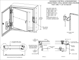
5.6. Use the four provided #12-24 pan head screws (Section 3 table, item 7) to mount the enclosure to the rack.
The mounting holes on the enclosure are notched for convenience. If there is space above the enclosure
when it’s being mounted then, the bottom two (2) screws can be partially threaded into the rack and the
enclosure can be dropped onto the screws (See figure 5c). The upper two screws can then be installed to
secure the enclosure to the rack (See figure 5d).
Figure 5c
Figure 5d

WWW.LEGRAND.US
INSTRUCTION SHEET, ACCESS
ENCLOSURE
DOCUMENT NUMBER
REV.
ECN #
SHEET
71602032
00
-
5 OF 15
6. ENCLOSURE FUNCTIONALITY
6.1. The enclosure has two (2) spring loaded thumb screws mounted on both the left and right sides of the
enclosure directly in front of the mounting ears (See figure 6a). These thumb screws can be used to lock the
enclosure in the closed position. This prevents the enclosure from sliding out on its own. The thumb screws
are slotted so that a flat head screwdriver can be used to lock and unlock the enclosure if space is limited.
6.2. To pull the enclosure out of the rack you must first unlock it by unscrewing the two locking thumb screws
from the previous step. Once unlocked, grab the enclosure by the handle on the front door and pull. The
enclosure will audibly lock at its full 10” extension (See figure 6b).
Figure 6a
Figure 6b
6.3. The cover of the enclosure is spring loaded and held in place with two (2) red release tabs. These tabs are
located on the left and right side of the enclosure next to the locking thumb screws (See figure 6c). Press
both tabs inward at the same time to release the cover (See figure 6d). Once the cover is open the door will
swing open freely.

WWW.LEGRAND.US
INSTRUCTION SHEET, ACCESS
ENCLOSURE
DOCUMENT NUMBER
REV.
ECN #
SHEET
71602032
00
-
6 OF 15
Figure 6c
Figure 6d
6.4. Alternatively, the door can be opened separate from the cover by pressing the two (2) black slide latches
downward at the same time to unlock the door from the cover then pulling it open with the handle (See
figures 6e and 6f).

WWW.LEGRAND.US
INSTRUCTION SHEET, ACCESS
ENCLOSURE
DOCUMENT NUMBER
REV.
ECN #
SHEET
71602032
00
-
7 OF 15
Figure 6e
Figure 6f
6.5. Once the enclosure is opened the user has easy access to both the MDC connectors at the front of the
enclosure as well as the acclAIM connectors in the back. Both can be accessed from the front of the rack.
Cut-outs in the base and rear cover give the user access to the patching field from above or below the
enclosure.
6.6. The labelling field (Section 3 table, item 4) is stuck to the bottom of the spring-loaded cover with Velcro dots
so that it can be removed.
6.7. To close the enclosure, you must first close the cover by pressing it downward with your hand at the center of
the cover along the front edge. Once the cover is closed the user can swing the door closed. The latch
points for the door are located on the front lip of the cover. If the user closes the door first, then it will not
have anything to latch to.
6.8. Once the cover and door are closed the user can slide the enclosure back into the rack. To unlock the
enclosure, press the two (2) release tabs located on the slide rails on the left and right side of the enclosure
(See figure 6g). With both tabs pressed the enclosure can be pushed into the rack.
6.9. Secure both locking thumb screws from figure 6a to lock the enclosure to the rack.

WWW.LEGRAND.US
INSTRUCTION SHEET, ACCESS
ENCLOSURE
DOCUMENT NUMBER
REV.
ECN #
SHEET
71602032
00
-
8 OF 15
Figure 6g

WWW.LEGRAND.US
INSTRUCTION SHEET, ACCESS
ENCLOSURE
DOCUMENT NUMBER
REV.
ECN #
SHEET
71602032
00
-
9 OF 15
7. CABLE ROUTING AND INSTALLATION (pre-term)
7.1. Refer to image 7a and 7b for fiber Installation and Routing in the front of the fiber Enclosure. Fibers should
come out of the sides, through the fiber managers and be routed as needed. Figure 7a shows an open view
of the enclosure, figure 7b shows a front view of the fiber enclosure when open. If the rack has fingers to
manage cable slack you must push them out of the way of the patch cord bundle when pulling the enclosure
out of the rack. Use the provided Velcro straps (Section 3 table, item 3) to help organize the patch cords
exiting the enclosure.
Figure 7a

WWW.LEGRAND.US
INSTRUCTION SHEET, ACCESS
ENCLOSURE
DOCUMENT NUMBER
REV.
ECN #
SHEET
71602032
00
-
10 OF 15
Figure 7b
7.2. Refer to Figures 7c, 7d, 7e, 7f, and 7g for fiber Installation and routing in the rear of the fiber Enclosure. The
fiber trunk gets mounted to the back of the enclosure using the Hi-loc mounts (Section 3 table, item 2).
Install the Hi-loc mount to the trunk at or before the breakout area using two zip ties (Section 3 table, item 8)
(See figure 7c). The rectangular key on the Hi-loc mount snaps into the white tray on the back of the
enclosure by first inserting it in the large rectangular cut out in the tray then pulling back until it audibly
snaps into place (See figures 7d, 7e, and 7f). If a trunk cable needs to be removed, then you can tilt the
trunk cable back slightly and pull the Hi-loc forward to pop it back out.

WWW.LEGRAND.US
INSTRUCTION SHEET, ACCESS
ENCLOSURE
DOCUMENT NUMBER
REV.
ECN #
SHEET
71602032
00
-
11 OF 15
Figure 7c
Figures 7d, 7e, and 7f
7.3. The individual breakouts can be wrapped around the spools as needed and plugged into the back of the
adapters (See figure 7g). The back of the adapters can be accessed from the front of the rack. About 12
inches of slack should be left at the end of the trunk so that the whole enclosure can slide forward out of the
rack. Make sure the trunk cables are routed directly into the back of the enclosure and not from the sides as
they will interfere with the enclosure’s drawer slides.

WWW.LEGRAND.US
INSTRUCTION SHEET, ACCESS
ENCLOSURE
DOCUMENT NUMBER
REV.
ECN #
SHEET
71602032
00
-
12 OF 15
Figure 7g

WWW.LEGRAND.US
INSTRUCTION SHEET, ACCESS
ENCLOSURE
DOCUMENT NUMBER
REV.
ECN #
SHEET
71602032
00
-
13 OF 15
8. CABLE ROUTING AND INSTALLATION (splicing)
8.1. The Access enclosure can be converted to use for splicing. Two (2) 144 fiber mass splice trays need to be
purchased to convert the rear cable management tray for splicing (See item 2 in section 4: Accessories
Purchased Separately).
8.2. Remove the large spools from the back of the enclosure by pressing the inside of each quarter spool to
release the clip and pull up to remove (See figure 8a).
Figure 8a
8.3. Each splice tray kit comes with four (4) small spools. There are four (4) rectangular cut-outs along the left
and right side of the rear tray (See figure 8b. The cut-outs are marked with circles.). Snap the spools into
these cut-outs.
Figure 8b

WWW.LEGRAND.US
INSTRUCTION SHEET, ACCESS
ENCLOSURE
DOCUMENT NUMBER
REV.
ECN #
SHEET
71602032
00
-
14 OF 15
8.4. Each splice tray kit also comes with two (2) Velcro straps. Slide the straps through the bridge lances in the
center of the rear fiber management tray (See figure 8c). Once the Velcro is in place the trays can be
stacked on top. Line up the first splice tray so that the molded rectangular features on the bottom of the tray
sit on top of the bridge lances (See figure 8d). The second tray stacks on top of the first tray. Split the
splicing evenly between both trays. Once splicing is complete the Velcro can be secured over the top. Make
sure to pull the Velcro tight so that both trays are secure (See figure 8e).
Figure 8c
Figure 8d

WWW.LEGRAND.US
INSTRUCTION SHEET, ACCESS
ENCLOSURE
DOCUMENT NUMBER
REV.
ECN #
SHEET
71602032
00
-
15 OF 15
8.5. See figure 8e below for recommended cable routing for splicing. The blunt end of the trunk should mount to
the rear of the tray using the provided Hi-loc mounts just like figures 7c, 7d, 7e, and 7f. Use a pair of spools
on one side of the tray to manage the blunt trunk cables being routed into the enclosure. Once spliced, use
the pair of spools on the opposite end to manage the pigtails being plugged into the back of the enclosure.
Once the first splice tray is filled a second can be stacked on top. Four (4) additional spools can be snapped
into the first set of spools to create a second layer. For the second tray it is recommended to use the
opposite side spools to manage cables for the trunk and pig tails. This will spread the cables out evenly.
Figure 8e
-
 1
1
-
 2
2
-
 3
3
-
 4
4
-
 5
5
-
 6
6
-
 7
7
-
 8
8
-
 9
9
-
 10
10
-
 11
11
-
 12
12
-
 13
13
-
 14
14
-
 15
15


Ortronics 205ANM08T-A Operating instructions
- Type
- Operating instructions
- This manual is also suitable for
Ask a question and I''ll find the answer in the document
Finding information in a document is now easier with AI
Related papers

Other documents
-
 SCE SCE-24EL2012SS6LP Installation guide
-
Legrand Fiber Optic Systems Rack-Mount User guide
-
 Hubbell Premise Wiring 778561 Installation guide
-
 TE Connectivity 1374463-4 Datasheet
-
-
 TE Connectivity 6417 2 055-01 Datasheet
-
TELRAN GJs03-M6AX-24-96C-I User manual
-
CommScope 3RU User manual
-
 Telect MDC-CB User manual
-
 TE Connectivity 559552-2 Datasheet


