Page is loading ...

PATENTS: U.S.05971402, U.S.05370507, U.S.06106246, U.S.13/536,439 6/30/2022 – MT25X-A
Phone: 800-669-1303 or 801-561-0303
Fax: 801-255-2312
e-mail: trebors[email protected]
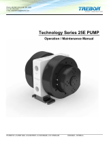
Technology Series 25X PUMP
Operation / Maintenance Manual

T25X PUMP OPERATION / MAINTENANCE MANUAL CONTENTS
CONTENTS
CONTENTS ......................................................................................................................... 2
1 UNPACKING ................................................................................................................ 3
1.1 CONTENTS ........................................................................................................ 3
2 OPTIONS ...................................................................................................................... 4
2.1 FLUID PORT CONNECTION OPTIONS ............................................................ 4
2.2 OPTIONAL LEAK SENSING .............................................................................. 5
2.2.a Probe Installation ................................................................................... 5
2.2.b Sensor Signal Specifications ................................................................. 5
2.3 OPTIONAL END-OF-STROKE PROBE ............................................................. 6
2.3.a Probe Installation ................................................................................... 6
3 INSTALLATION ............................................................................................................ 7
3.1 UTILITIES ........................................................................................................... 7
3.2 INSTALL AND START UP .................................................................................. 7
3.3 CONTROLLER ................................................................................................... 7
4 PERFORMANCE .......................................................................................................... 8
4.1 PUMP FLOW ...................................................................................................... 8
4.2 PUMP PRESSURE............................................................................................. 9
5 MAINTENANCE .......................................................................................................... 11
5.1 PREVENTIVE MAINTENANCE SCHEDULE ................................................... 11
5.2 PUMP REBUILD SERVICE .............................................................................. 11
6 PC15 (OPTIONAL) INSTALLATION .......................................................................... 12
6.1 PC15 OVERVIEW ............................................................................................ 12
6.2 PC15 INSTALLATION ...................................................................................... 12
6.3 PC15 UTILITIES / HOOK-UP ........................................................................... 13
6.4 PC15 CONTROLLER OPERATION ................................................................. 14
6.4.a Turning Pump On and Off ................................................................... 14
7 DISASSEMBLY/ASSEMBLY ..................................................................................... 16
7.1 PARTS ILLUSTRATION ................................................................................... 16
7.2 PARTS LIST ..................................................................................................... 17
7.3 CLEAN-UP ........................................................................................................ 17
7.4 DISASSEMBLY ................................................................................................ 18
7.4.a Body Disassembly ................................................................................. 18
7.5 ASSEMBLY ...................................................................................................... 21
7.5.a Body Assembly .................................................................................... 21
7.5.b Head Assembly ................................................................................... 25
7.5.c Body-Head Assembly .......................................................................... 26
7.6 RECOMMENDED SPARE PARTS AND KITS ................................................. 27
7.7 TOOLS .............................................................................................................. 28
8 TESTING ..................................................................................................................... 29
8.1 PERFORMANCE TEST ................................................................................... 29
8.2 PUMP DRYING PROCEDURE ........................................................................ 29
8.3 DRY SUCTION TEST ....................................................................................... 29
9 TROUBLESHOOTING................................................................................................ 30
10 WARRANTY ....................................................................................................... 32
11 CONTACT INFORMATION ........................................................................................ 34
11.1 GENERAL CONTACT INFORMATION ............................................................ 34
11.2 TECHNICAL SUPPORT ................................................................................... 34
11.3 REGIONAL REPRESENTATIVES ................................................................... 34
APPENDIX ........................................................................................................................ 35

T25X PUMP OPERATION / MAINTENANCE MANUAL PAGE 3
1 UNPACKING
1.1 CONTENTS
After unpacking, the pump should be checked for any damage that may have occurred
during shipment. Damage should be reported to the carrier immediately.
The following items should be included within the shipping container:
Qty
Item
Description
1
Pump
T25X Pump
1
MT25X
Operation/Maintenance Manual
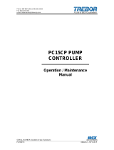
NOTE: Although extensive efforts are made to deliver dry pumps to our
customers, new pumps may contain residual moisture from DI water testing.
Figure 1-1: Dimensional Views

PAGE 4 T25X PUMP OPERATION / MAINTENANCE MANUAL
2 OPTIONS
2.1 FLUID PORT CONNECTION OPTIONS
NOTE: Use O-ring to seal stainless steel or other rigid plumbing.
Available Options
Fluid Connection Fittings:
• 1/2” PFA Pipe Stub Out (T25B08)
• 3/8” PTFE Flare Fitting (T25F06)
• 1/2” PTFE Flare Fitting (T25F08)
• 3/4” PTFE Flare Fitting (T25F12)
• 1/2” PTFE FNPT Fitting (T25P08)
• 1/2” Pillar Fitting (T25X08)
Torque fluid fittings to 27 in-lbs using dial torque wrench (T0210) and wrench offsets
(T0213) or (T0214). Do not over torque!
PFA Pipe Stub Out
The T-25 pump can use an ultrapure PFA fluid port adapter. One end of the adapter
screws into the pump port and the other end is ½” pipe, to which a PFA fitting can be
fusion welded. Figure 2-1 shows stub-out fitting and gasket.
Figure 2-1: Fluid Port Pipe Stub Out
If additional pipe fitting types are needed, contact your sales associate. Custom
configurations are available to adapt the T25 pump to other facility configuration.

T25X PUMP OPERATION / MAINTENANCE MANUAL PAGE 5
2.2 OPTIONAL LEAK SENSING
2.2.a Probe Installation
• Remove leak port plug (TJ004) and seal (TJ005) from the head.
• Thread probe cap into port and torque to 32 in-lbs using torque wrench (T0210) and
wrench offset (T0217). Do not overtorque!
• Connect fiber optic cable to sensor.
NOTE: Minimize bends in fiber optic cable to 2” radius minimum to help ensure
optimum signal strength.) Fiber optic cable can be cut to desired length using a
proper cable cutter.
2.2.b Sensor Signal Specifications
• The sensor signal is normally closed. In the event of a leak, no light signal is returned
to the sensor. See fiber optic sensor installation instructions for proper connection
and adjustment.
Figure 2-2: Leak Probe Assembly

PAGE 6 T25X PUMP OPERATION / MAINTENANCE MANUAL
2.3 OPTIONAL END-OF-STROKE PROBE
2.3.a Probe Installation
• Remove pilot cap (TJ001) and pilot cap seal (AM020).
• Place new pilot cap seal (AM020) into pilot port.
• Thread the fiber optic assembly into the pilot port and tighten to 45 in-lbs using a 3/4”
fiber optic pin tool (T0149), torque wrench (T0210) and wrench offset (T0216).
• Connect fiber optic cable to sensor.
NOTE: Minimize bends in fiber optic cable to 2” radius minimum to help ensure
optimum signal strength. Fiber optic cable can be cut to desired length using a
proper cable cutter (98002986).
Figure 2-3: End of Stroke Probe Assembly

T25X PUMP OPERATION / MAINTENANCE MANUAL PAGE 7
3 INSTALLATION
3.1 UTILITIES
It is recommended that the pump be positioned within 15° from level to maintain self-
priming ability and pumping efficiency. Allow sufficient room for tubing connectors.
Pump mounts on a quick-change base for easy installation. It is recommended that a
filter be placed on the discharge side of the pump.
Air Inlet: 1/4” FNPT (3/8” Dia. [8mm] supply tube minimum).
Air Supply: 20-80 psig (.14 - .55 MPa) clean dry air or nitrogen (see Performance
Charts, Section 4).
Fluid Ports: Inlet/Outlet adaptor fittings and Surge Suppressor require torque
application during pump installation.
NOTE: The pump should be operated with clean, dry air or nitrogen.
Particulate, water and oils in the air supply can damage the pump.
3.2 INSTALL AND START UP
• Pump air supply pressure must be regulated.
• Open the fluid suction (IN) line valve, if necessary.
• Open the fluid discharge (OUT) line valve, if necessary.
• Program external control to desired settings (must use PC15 Controller).
• Start slowly with air regulator at low (> 20 psi) pressure setting. Increase pressure to
attain desired flow, up to the maximum rating
• Refer to Troubleshooting, Section , if pump fails to start.
3.3 CONTROLLER
The T25X cross-phase pump requires the Trebor PC15CP controller.

PAGE 8 T25X PUMP OPERATION / MAINTENANCE MANUAL
4 PERFORMANCE
4.1 PUMP FLOW
Figure 4-1: Cycle Rate to Flow Pump Performance Curve
NOTE: Test information is based on specific conditions and limited sampling.
Use for general reference only.
Pumping capacity is a function of air supply pressure and volume, suction head,
suction line restrictions, discharge head, discharge line restriction, and fluid
specific gravity and viscosity. Specification should be used to size regulators and
control valves.
Figure 4-1 shows the approximate cycle rate to achieve the flow shown. Figure 4-2
shows the discharge pressures that the given flow is achievable.

T25X PUMP OPERATION / MAINTENANCE MANUAL PAGE 9
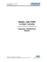
Figure 4-2: Pressure and Flow Capacity
4.2 PUMP PRESSURE
Figure 4-3: Pressure vs. Fluid Temperature Chart
Recommended Maximum Pump Operating Levels

PAGE 10 T25X PUMP OPERATION / MAINTENANCE MANUAL
NOTE: Test information is based on specific conditions and limited sampling.
Use for general reference only.
CAUTION: When handling potentially dangerous fluids under pressure, the pump
and its fittings should be placed in an enclosure away from operators.
Be sure that fittings and tubing used are capable of these operating conditions.
Noise level while operating is approximately 80 dB.

T25X PUMP OPERATION / MAINTENANCE MANUAL PAGE 11
5 MAINTENANCE
Trebor pump maintenance can be divided into two categories: air system maintenance
and fluid system maintenance. The purpose of air system maintenance is to prevent air
system failures such as stalling or erratic cycling. The purpose of fluid system
maintenance is to maintain suction and lift capabilities.
5.1 PREVENTIVE MAINTENANCE SCHEDULE
The following maintenance schedule is recommended to optimize pump performance
and minimize failures. Certain operating conditions and application may require more
frequent maintenance intervals. In positive pressure inlet conditions where suction or lift
is not required, fluid system maintenance may be extended.
Adhering to the recommended preventative maintenance schedule along with periodic
inspection of the pump will ensure continued efficient operation and overall reliable
pump performance. It is recommended that the Preventive Maintenance Record be
copied, maintained and kept with this unit for future reference.
T25D Maintenance Schedule
Install
30 Days
3 Months
6 Months
9 Months
12 Months
15 Months
18 Months
21 Months
24 Months
Check Balls and O-Rings
R
Diaphragms
R
Check Cap Seal
R
Suction and Discharge Check Cage
I
I=Inspect, R=Replace
See Appendix for Maintenance Log
5.2 PUMP REBUILD SERVICE
Trebor International provides a factory rebuild service for customers using Trebor products.
Trebor will rebuild any standard pump (exclusive of options). Please contact Trebor International
Sales Department for current rebuild pricing. The fixed rebuild price includes a factory rebuild
and parts equivalent to the standard rebuild kit. Each factory rebuild comes with a new one year
warranty. Repairs requiring more extensive part replacements will be quoted prior to proceeding
with the pump rebuild. If the pump has exceeded its useful life and cannot be rebuilt, the
customer may elect to purchase a new Trebor pump. If the customer chooses not to rebuild or
replace the pump, an evaluation fee will be required.
All returned pumps are to be shipped freight prepaid with a valid Purchase Order for the cost of
rebuild service. Please contact Trebor International prior to returning your pump to obtain an
RMA Number and Pump Return Data Sheet to ensure proper safety precautions.

PAGE 12 T25X PUMP OPERATION / MAINTENANCE MANUAL
6 PC15 (OPTIONAL) INSTALLATION
6.1 PC15 OVERVIEW
The PC15 Pump Controller is designed specifically to operate Trebor’s T25X pump.
Cross-phase timing results in overlapping pump strokes which produces a near pulse-
less pump output. PC15 controllers can be configured depending on flow requirements
(See QIG manual)
6.2 PC15 INSTALLATION
The PC15 pump controller can be installed in any orientation. Pump controller mounts
using four ¼” (6mm) bolts and should be mounted above the level of the fluid feeding the
pump. Allow clearance for tubing connectors.
Figure 6-1 Dimension (in / [mm])

T25X PUMP OPERATION / MAINTENANCE MANUAL PAGE 13
6.3 PC15 UTILITIES / HOOK-UP
Utility Pump
Air Inlet: • 3/8” Diameter supply tube.
Air Supply: • 50-80 PSIG (.55±.03 MPa Max), clean dry air or inert
gas
Power • 24VDC - 500mA
Controller Weight: • 4.4 lbs (2.0 Kg)
ATTENTION: Air supplied to the PC15 pump controller must be regulated to 50 - 80
PSIG to operate the vacuum venturi. An onboard precision regulator controls pump air
supply pressure.
• Air supply connections between the pump and the pump controller are required.
NOTE: 3/8” tubing required for distances not to exceed 4 meters between the pump and
the pump controller.
• 24VDC is required to operate the pump controller.
o Terminal blocks are insulation displacement type. Insert 22-16 awg wires into
the indicated location and rock lever to engage connection, see Figure 6-2.
NOTE: Follow local wiring codes and applicable wiring standards to insure proper power
and over-current protection.

PAGE 14 T25X PUMP OPERATION / MAINTENANCE MANUAL
Figure 6-2: 24VDC Connection
6.4 PC15 CONTROLLER OPERATION
Ensure that all system interlock and safety devices are functional prior to operation.
Before starting the system, it is important to read and understand the PC15PC manual.
Only trained, qualified, authorized personnel should operate this pump controller.
The controller is operated by using the buttons located on the PLR, see Table 6-1.
Table 6-1: PLC Buttons
Button
Normal mode
Numeric value change mode
(while digit is flashing)
Scroll through Menu pages.
Activates setup pages when depressed
during Home page.
Enables/Disables controller
cycling.
Activates controller when depressed during
Home page.
Increases pump cycle rate on
Home page.
Increases value of digital readout.
Decreases pump cycle rate on
Home page.
Reduces value of digital readout.
Maintenance alarm page.
Displays the Maintenance alarm page
Return to home page
Displays the Home page.
6.4.a Turning Pump On and Off
From the Home Page, pressing the RIGHT arrow key () will start and stop the
cycling of the pump controller. When activated a cursor will be located below
position 3 (Figure 6-3), accompanied by an oscillating curser between positions 1
& 2 (Figure 6-3).

T25X PUMP OPERATION / MAINTENANCE MANUAL PAGE 15
Figure 6-3: Controller Off Figure 6-4: Controller Cycling
NOTE: See PC15 manual for additional instructions, requirements, limitations and
troubleshooting.

PAGE 16 T25X PUMP OPERATION / MAINTENANCE MANUAL
7 DISASSEMBLY/ASSEMBLY
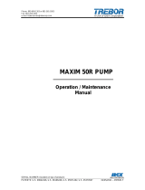
7.1 PARTS ILLUSTRATION
Figure 7-1: T25X Itemized Parts

T25X PUMP OPERATION / MAINTENANCE MANUAL PAGE 17
7.2 PARTS LIST
ILL NO
PART NO
QTY
DESCRIPTION
PM
year
#
material
1
TA015
2
Check Port Cap
PTFE
2
AM082
2
Check Port Seal
2
PTFE
3
TA013
2
Discharge Sleeve
PTFE
4
98004341
2
Check Ball, PTFE, 1/2”
2
PTFE
5
98004346
2
Check Sleeve O-Ring
2
PTFE
6
TA012
2
Suction Sleeve
PTFE
7
98003211
2
Check Bal, PTFE, 5/8”
2
PTFE
8
98003212
2
Check Valve O-Ring
2
PTFE
9
TA011
2
Check Seat Wear Ring
PFA
10
TA001
1
Body
PTFE
11
Not Used
-
-
-
-
12
TJ006
12
Pin, Diaphragm
PP
13
Not Used
-
-
-
-
14
Not Used
-
-
-
-
15
Not Used
-
-
-
-
16
Not Used
-
-
-
-
17
TA008
4
Diaphragm
2
PTFE
18
TJ007
2
Fiber Optic Target
2
PTFE
19
Not Used
-
-
-
-
20
TA002
2
Head
PP
21
Not Used
-
-
-
-
22
Not Used
-
-
-
-
23
TJ005
6
Seal, Leak Port
PTFE
24
AK120
2
Seal, Pilot
PTFE
25
TJ004
6
Plug, Leak Port
PP
26
TA019
2
Pilot Plug
PP
27
AM020
2
Seal, Pilot Cap
PTFE
28
TJ001
2
Cap, Pilot
PP
29
TA010
2
Slip Washer
PTFE
30
TA003
2
Union Nut
PP
31
98004392
6
Screw, Union Nut
PTFE - SS
32
TA016
2
Base
PP
33
98003207
4
Screw, Base
PP
34
Not Used
-
-
-
-
35
98003080
2
Plug, 1/4”
HDPE
7.3 CLEAN-UP
To help remove potentially dangerous chemicals prior to service or shipment, the pump
should be flushed with DI water or disassembled and thoroughly cleaned. Allow DI water
to flush through the inlet and out the outlet to prevent pressure build up.
Caution: Use appropriate personal protection equipment when handling pump.

PAGE 18 T25X PUMP OPERATION / MAINTENANCE MANUAL
7.4 DISASSEMBLY
During the life of the pump it will be necessary to perform certain preventative
maintenance procedures to ensure its continued high performance. This section and the
next (7.5 Assembly) are provided for the user’s convenience in disassembly and re-
assembly procedures.
7.4.a Body Disassembly
• Remove union nut screws (98004392) from union nut using 1/8” allen wrench
(T0208).
• Remove the bases (TA016) from the pump body using a slotted screw driver (T0211)
to remove the 4 mounting screws (98003207).
Figure 7-2: Base and Union Nut Screw Removal

T25X PUMP OPERATION / MAINTENANCE MANUAL PAGE 19
• Install mounting plugs in pump fluid ports and lock body into bench mounting fixture.
NOTE: Securely attach mounting fixture to work surface using hardware provided as
part of the rebuild fixture (T0189).
Figure 7-3: Rebuild Fixture Mounting

PAGE 20 T25X PUMP OPERATION / MAINTENANCE MANUAL
• Using strap wrench (T0129) and wrench (T0212) turn union nut counter-clockwise
facing the union nut to remove. Repeat for second union nut.
Figure 7-4: Union Nut Removal
• Remove the heads and inspect the diaphragms for integrity.
• To remove the diaphragms, slit diaphragms with a sharp blade (ST0018) being
careful not to contact the body of the pump. Remove the diaphragms from the
grooves by reaching inside the slit region of the diaphragm and pulling upward.
Note: (Do not pry on diaphragm seal groove, as this will damage the sealing
surface.)
• Remove check caps (TA015) using 1/2” pin tool (T0148) and driver (98003305) and
remove check port seals (AM082).
• To prevent check valve components from rolling out of the check bore, the pump
must be removed from the rebuild fixture and placed upright on working surface by
this time.
• Remove discharge sleeves (TA013) with the assistance of the check sleeve puller
(T000B0014). Note: Take care to ensure that the sleeve puller does not to come into
contact with the pump body during removal process.
• Cover the check ports by hand and turn pump over 180° to allow the check balls
(98004341) and check rings (98004346) to release from the check bore.
• Remove suction sleeves with the assistance of the check sleeve puller (T000B0014).
Note: Take care to ensure that the sleeve puller does not to come into contact with
the pump body during removal process.
• Cover the check ports by hand and turn pump over 180° to allow the suction check
balls (98003211) and check rings (98003212) to release from the check bore.
• Using the sleeve puller (T000B0014), carefully remove the check seat wear rings
(TA011) from the bottom of the check bores.
/