Page is loading ...

BD-Sensors-Str.1; 95199 Thierstein
Phone: +49 (0) 92 35 / 98 11 0 | www.bdsensors.de
© 2019 BD|SENSORS GmbH – All rights reserved.
Operating Manual
Differential pressure transmitter for IS-areas
DX13A-DMD331, DX13A-DMD331_54X
READ THOROUGHLY BEFORE USING THE DEVICE
KEEP FOR FUTURE REFERENCE
ID: BA_DMD_Ex_E | version: 09.2019.0
1. General and Safety-Related Information on
this Operating Manual
This operating manual enables safe and proper handling of the
product, and forms part of the device. It should be kept in close
proximity to the place of use, accessible for staff members at any
time.
All persons entrusted with the mounting, installation, putting into
service, operation, maintenance, removal from service, and
disposal of the device must have read and understood the
operating manual and in particular the safety-related information.
The following documents are an important part of the
operating manual:
- Data sheet
- Type-examination certificate
For specific data on the individual transmitter, please refer to the
respective data sheet.
Download these by accessing www.bdsensors.de or request
them: [email protected] | phone.: +49 (0) 92 35 / 98 11 0
The IS versions of our products are variants of the standard
products.
Example:
Standard: DMD 331 IS-version: DX13A-DMD 331
In addition, the applicable accident prevention regulations, safety
requirements, and country-specific installation standards as well
as the accepted engineering standards must be observed.
For the installation, maintenance and cleaning of the device, the
relevant regulations and provisions on explosion protection
(VDE0160, VDE 0165 and/or EN 60079-14) as well as the
accident prevention regulations must absolutely be observed. The
device was designed by applying the following standards:
DX13A: EN60079-0:2012+A11:2013
EN60079-11:2012
1.1 Symbols Used
Warning word
- Type and source of danger
- Measures to avoid the danger
Warning word
Meaning
DANGER
- Imminent danger!
- Non-compliance will result in
death or serious injury.
WARNING
- Possible danger!
- Non-compliance may result in
death or serious injury.
CAUTION
- Hazardous situation!
- Non-compliance may result in
minor or moderate injury.
NOTE
- draws attention to a possibly hazardous situation that
may result in property damage in case of non-compliance.
Precondition of an action
1.2 Staff Qualification
Qualified persons are persons that are familiar with the
mounting, installation, putting into service, operation,
maintenance, removal from service, and disposal of the product
and have the appropriate qualification for their activity.
This includes persons that meet at least one of the following three
requirements:
-
They know the safety concepts of measuring and
automation technology and are familiar therewith as
project staff.
-
They are operating staff of the measuring and automation
systems and have been instructed in the handling of the
systems. They are familiar with the operation of the
devices and technologies described in this documentation.
-
They are commissioning specialists or are employed in
the service department and have completed training that
qualifies them for the repair of the system. In addition,
they are authorized to put into operation, to ground, and to
mark circuits and devices according to the safety
engineering standards.
All work with this product must be carried out by qualified
persons!
1.3 Intended Use
The devices are used to convert the physical parameter of
pressure into an electric signal.
The differential pressure transmitter DMD 331 is intended for
industrial applications. For both sided pressure admission, the
difference of the pressure between positive and negative side is
established and converted into a proportional electrical signal.
The DMD 331 is intended e.g. in engineering and plant
construction for filter controlling and flow measurement as well as
in hydraulic applications.
This operating manual applies to devices with explosion
protection approval and is intended for the use in IS-areas.
A device has an explosion-protection approval if this was
specified in the purchase order and confirmed in our order
acknowledgement. In addition, the manufacturing label includes a
sign.
The user must check whether the device is suited for the selected
use. In case of doubt, please contact our sales department:
[email protected] | phone: +49 (0) 92 35 / 98 11 0
BD|SENSORS assumes no liability for any wrong selection and
the consequences thereof!
Permissible media are gases or liquids, which are compatible with
the media wetted parts described in the data sheet.
The technical data listed in the current data sheet are engaging
and must absolutely be complied with. If the data sheet is not
available, please order or download it from our homepage:
http://www.bdsensors.de
WARNING
Danger through incorrect use
- In order to avoid accidents, use the
device only in accordance with its
intended use.
1.4 Limitation of Liability and Warranty
Failure to observe the instructions or technical regulations,
improper use and use not as intended, and alteration of or
damage to the device will result in the forfeiture of warranty and
liability claims.
1.5 Safe Handling
NOTE -
Do not use any force when installing the device to
prevent damage of the device and the plant!
NOTE -
Treat the device with care both in the packed and
unpacked condition!
NOTE -
The device must not be altered or modified in any way.
NOTE -
Do not throw or drop the device!
NOTE -
Excessive dust accumulation (over 5 mm) and
complete coverage with dust must be prevented!
NOTE -
The device is state-of-the-art and is operationally
reliable. Residual hazards may originate from the device if it is
used or operated improperly.
1.6 Safety-Related Maximum Values
U
i
= 28 V; I
i
= 93 mA; P
i
= 660 mW; C
i
≤ 1 nF; L
i
≤ 10 µH;
with respect to the housing, the supply connections have an
interior capacity of max. 27 nF
Range of ambient temperature
DX13A-DMD 331:
Use in zone 1: -25 ... 65 °C
DX13A-DMD 331_54X:
Use in zone 0 (p
atm
0.8 bar to 1.1 bar): -20 ... 60 °C
Use in zone 1: -25 ... 65 °C
1.7 Scope of Delivery
Check that all parts listed in the scope of delivery are included
free of damage, and have been delivered according to your
purchase order:
- differential pressure transmitter
- this operating manual
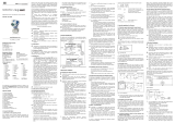
2. Product Identification
The device can be identified by its manufacturing label. It
provides the most important data. By the ordering code the
product can be clearly identified.
Fig. 1 Example of manufacturing label
NOTE -
The manufacturing label may not be removed!
The marking of equipment with an IS approval has to include
the following:
EC-type examination certificate: IBExU08ATEX1125 X
Designation:
DX13A-DMD 331:
II 2G Ex ia IIC T4 Gb
II 2D Ex ia IIIC T85°C Db
DX13A-DMD 331_54x:
II 1G Ex ia IIC T4 Ga
II 1D Ex ia IIIC T85°C Da
3. Mounting
3.1 Mounting and Safety Instructions
DANGER
Danger of death from explosion,
airborne parts, leaking fluid, electric
shock
-
Always mount the device in a
depressurized and de-energized
condition!
-
Do not install the device while there is
a risk of explosion.
NOTE -
The technical data listed in the EC type-examination
certificate are binding. Download these by accessing
www.bdsensors.de or request them:
[email protected] | Tel.: +49 (0) 92 35 / 98 11 0
NOTE -
Make sure that the entire interconnection of intrinsically
safe components remains intrinsically safe. The owner-operator is
responsible for the intrinsic safety of the overall system (entire
circuitry).
NOTE -
Make sure that an equipotential bonding is in place for
the entire course of the line, both inside and outside the intrinsic
area.
NOTE -
Treat any unprotected diaphragm with utmost care; this
can be damaged very easily.
NOTE -
Provide for a cooling section if the device is used in a
steam line.
NOTE -
Do not mount the device in a pneumatic flow rate!
NOTE -
When installing the device, avoid high mechanical
stresses on the pressure port! This will result in a shift of the
characteristic curve or to damage, in particular in case of very
small pressure ranges and devices with pressure ports made of
plastic.
NOTE -
For the connection of the pressure lines, a sealing has
to be installed by the operator.
NOTE -
For the pipe assembly, a stress free installation must
be observed.
NOTE -
Consider for the installation that the pressure ports
must not be turned against the housing!
NOTE -
Do not remove the packaging or protective caps of the
device until shortly before the mounting procedure, in order to
exclude any damage to the diaphragm and the threads!
Protective caps must be kept! Dispose of the packaging properly!
NOTE -
The specified tightening torques must not be exceeded!
NOTES -
for mounting outdoors or in a moist
environment:
- Please note that your application does not show a dew point,
which causes condensation and can damage the pressure
transmitter. There are specially protected pressure transmitters
for these operating conditions. Please contact us in such case.
- Connect the device electrically straightaway after mounting or
prevent moisture penetration, e.g. by a suitable protective cap.
(The ingress protection specified in the data sheet applies to
the connected device.)
- Select the mounting position such that splashed and
condensed water can drain off. Stationary liquid on sealing
surfaces must be excluded!
- For devices with cable socket, the outgoing cable must be
routed downwards. If the cable needs to be routed upwards,
this must be done in an initially downward curve.
- Mount the device such that it is protected from direct solar
radiation. In the most unfavourable case, direct solar radiation
leads to the exceeding of the permissible operating
temperature. This must be excluded if the device is used in any
IS area!
- If installing the device outdoor and there is any danger of
lightning or overpressure, we suggest putting an overpressure
protection unit between the supply / switch cabinet and the
device to prevent damage.
3.2 General Mounting Steps
1. Connect the reference pressures according to the following
installation steps. Therefore, keep in mind that the higher
pressure has to be connected with input "p+"; lower pressure
has to be connected with input "p-".
2. Fix the device according to your demands on the holder or
holding angle intended for it. For mounting the device,
mounting threads are provided. (DMD 331: four threads M4 -
10 deep. The exact position is defined in the data sheet.
3.3
Installation steps for G 1/2" acc. to EN 837
The sealing surfaces are perfectly smooth and clean.
(R
Z
6.3)
For each pressure port a suitable cooper gaskets,
corresponding to the diameter of the threads which should
be screwed in, is used. (seals are not included in the scope
of delivery)
1 Screw the fittings into the threads by hand.
2 To tighten the fittings properly, hold the DMD 331 on the
spanner flat SW 22 of the respective pressure port with one
hand and then tighten it (max. 50 Nm).
3.4
Installation steps for G 1/4" internal thread
Suitable seals for the measured fluid and the pressure to be
measured are available.
The sealing surfaces of the fittings are perfectly smooth and
clean. (R
Z
6.3)
1 Screw the fittings into the threads by hand.
2 To tighten the fittings properly, hold the DMD 331 on the
spanner flat SW 22 of the respective pressure port with one
hand and then tighten it. The torque depends on the
counterpart (permissible tightening torque for the device is
20 Nm max).
3.5
Installation steps for G 7/16" UNF
The pressure ports of the differential pressure transmitter
are sealed in a way that is suitable for your application.
(seals are not included in the scope of delivery)
1 Screw your fittings by hand onto the threads.
2 To tighten the fittings properly, hold the DMD 331 on the
spanner flat SW 22 of the respective pressure port with one
hand and then tighten it (max. 30 Nm).
4. Electrical Connection
4.1 Connection and Safety Instructions
DANGER
Danger of death from electric shock
or explosion
- Explosion hazard if the operating
voltage is too high (max. 28 V
DC
).
-
Always mount the device in a
depressurized and de-energized
condition!
-
Do not install the device while there is
a risk of explosion.
- Operate the device only within the
specification! (data sheet)
- Improper installation may result in
electric shock.
The limit values listed in the EC type-examination
certificate are observed. (Capacity and inductance of the
connection cable are not included in the values.)
The supply corresponds to protection class III (protective
insulation).
NOTE -
for device with ISO 4400 plug and socket
- Please note that the socket has to be mounted properly to
ensure the ingress protection mentioned in the data sheet.
Please check if the delivered seal is placed between plug
and cable socket. After connecting the cable fasten the
cable socket on the device by using the screw.
- It must be ensured that the external diameter of the
used cable is within the allowed clamping range
(Ø 4 … 6 mm). Moreover you have to ensure that it lies
in the cable gland firmly and cleftlessly!
NOTE -
Use a shielded and twisted multicore cable for the
electrical connection.
4.2 Conditions for the IS-Area
Danger generated by electrostatic charging
DANGER
Danger of death from explosion
-
Explosion hazard due to spark
formation from electrostatic charging
of plastic components.
-
Generally, a shielded cable must be
used.
-
For devices with cable outlet, the cable
must be installed tightly.
-
Avoid friction on the plastic surfaces
-
Do not clean the device and, if
applicable, the connection cable, in a
dry state! Use a moist cloth, for
example.
Overvoltage protection
If the pressure transmitter is used as electrical equipment of
category 1 G, then a suitable overvoltage protection device must
be connected in series (attend the valid regulations for operating
safety as well as EN60079-14).
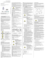
Schematic circuit
The operation of an intrinsically safe transmitter in intrinsic safe
areas requires special care when selecting the necessary Zener
barrier or transmitter repeater devices to allow the utilization of
the device’s properties to the full extent. The following diagram
shows a typical arrangement of power supply, Zener barrier and
transmitter.
Fig. 2 circuit diagrams
NOTE -
Observe item (17) of the type-examination certificate
which specifies special conditions for intrinsically safe operation.
Exemplary circuit description
The supply voltage of e.g. 24 V
DC
provided by the power supply is
led across the Zener barrier. The Zener barrier contains series
resistances and breakdown diodes as protective components.
Subsequently, the operating voltage is applied to the transmitter
and, depending on the pressure, a particular signal current flows.
DANGER
Danger of death from explosion
-
Operation of intrinsically safe devices
as zone-0 equipment only with
ungrounded and galvanically isolated
power supply.
Functional selection criteria for Zener barriers and
galvanic power supply
The minimum supply voltage V
S min
of the transmitter must not fall
short since a correct function of the device can otherwise not be
guaranteed. The minimum supply voltage has been defined in the
respective product-specific data sheet under "Output signal /
supply".
When using a galvanically insulated amplifier with linear bonding,
note that the terminal voltage of the transmitter will decrease like
it does with a Zener barrier. Furthermore, you have to note that
the supply will additionally decrease with an optionally used
signal amplifier.
Test criteria for the selection of the Zener barrier
In order not to fall below V
S min
, it is important to verify which
minimum supply voltage is available at full level control of the
transmitter. The full level control, i.e. a maximum or nominal
output signal (20 mA), can be reached by applying the maximum
physical input signal (pressure).
The technical data of the barrier will usually provide the
information needed for the selection of the Zener barrier.
However, the value can also be calculated. If a maximum signal
current of 0.02 A is assumed, then – according to Ohm’s law – a
particular voltage drop will result from the series resistance of the
Zener barrier.
This voltage drop is subtracted by the voltage of the power supply
and as a result, the terminal voltage is obtained which is applied
on the transmitter at full level control. If this voltage is smaller
than the minimum supply voltage, another barrier or a higher
supply voltage should be chosen.
NOTE -
When selecting the supplied devices / Zener barrier,
the maximum operating conditions according to the EC type-
examination certificate must be observed. When assessing these,
refer to their current data sheets to ensure that the entire
interconnection of intrinsically safe components remains
intrinsically safe.
Calculation example for the selection of the Zener
barrier
The nominal voltage of the power supply in front of the Zener
barrier is 24 V
DC
± 5 %. This results in:
- maximum supply voltage:
V
Sup max
= 24 V * 1.05 = 25.2 V
- minimum supply voltage:
V
Sup min
= 24 V * 0.95 = 22.8 V
The series resistance of the Zener barrier is listed with 295 ohm.
The following values must still be calculated:
- voltage drop at the barrier (with full conduction):
V
ab barrier
= 295 * 0.02 A = 5.9 V
- terminal voltage at the transmitter with Zener barrier:
V
Kl
= V
S up min
– V
ab Barriere
= 22.8 V – 5.9 V = 16.9 V
- minimum supply voltage of the transmitter,
(according to data sheet):
V
Kl min
= 12 V
DC
(corresponding to V
S min
)
Condition:
V
Kl
≥ V
Kl min
Result:
The terminal voltage of the transmitter with Zener barrier lies at
16.9 V and is therefore higher than the minimum supply voltage
of the transmitter which lies at 12 V
DC
. This means, the Zener
barrier has been selected correctly regarding the supply voltage.
NOTE -
Note that no line resistances have been listed in this
calculation. However, these will lead to an additional voltage drop
that must be taken into account.
transmitter
+V
S
V
S
Zener barrier
+V
S
-V
S
power suppl
y
transmitter amplifier supply
shielded cable
IS-area secure area
0637
input "p+" input "p-"
Type- Ordering code Serial number
designation
EC-type examination certificate no.
Device category and zone, explosion marking
Safety-related maximum values

4.3 Electrical Installation
Establish the electrical connection of the device according to the
technical data shown on the manufacturing label, the following
table and the wiring diagram.
Pin configuration:
Electrical
connections ISO 4400 Brad
Harrison
M12x1
(4-pin)
Supply +
Supply
1
2
A
B
1
2
Shield
ground pin
C 4
Wiring diagram:
5. Commissioning
DANGER
Danger of death from explosion,
airborne parts, leaking fluid,
electric shock
- Explosion hazard if the operating
voltage is too high (max. 28 VDC)!
- Operate the device only within the
specification! (according to data sheet)
The device has been installed properly
The device does not have any visible defect
The device is operated within the specification.
(see data sheet and EC type-examination certificate)
Please note that for starting up, the device has to be stressed by
pressure simultaneously at both pressure ports. Otherwise the
sensor could be damaged. For one-sided pressure admission, the
permissible static pressure (one-sided) must be attended. Please
take this out of the current data sheet.
6. Maintenance
DANGER
Danger of death from airborne parts,
leaking fluids, electric shock
- Always service the device in a
depressurized and de-energized
condition!
WARNING
Danger of injury from aggressive fluids
or pollutants
- Depending on the measured medium,
this may constitute a danger to the
operator.
- Wear suitable protective clothing
e.g. gloves, safety goggles.
If necessary, clean the housing of the device using a moist cloth
and a non-aggressive cleaning solution.
The cleaning medium for the media wetted parts (pressure port /
diaphragm / seal) may be gases or liquids which are compatible
with the selected materials. Also observe the permissible
temperature range according to the data sheet.
Deposits or contamination may occur on the diaphragm /
pressure port in case of certain media. Depending on the quality
of the process, suitable maintenance intervals must be specified
by the operator. As part of this, regular checks must be carried
out regarding corrosion, damage to the diaphragm and signal
shift.
If the diaphragm is calcified, it is recommended to send the
device to BD SENSORS for decalcification. Please note the
chapter “Service/Repair” below.
NOTE - Wrong cleaning or improper touch may cause an
irreparable damage on the diaphragm. Therefore, never use
pointed objects or pressured air for cleaning the diaphragm.
7. Troubleshooting
DANGER
Danger of death from airborne parts,
leaking fluids, electric shock
- If malfunctions cannot be resolved, put
the device out of service (proceed
according to chapter 8 up to 10)
DANGER
Danger of death from explosion
- As a matter of principle, work on
energized parts, except for intrinsically
safe circuits, is prohibited while there is
an explosion hazard.
NOTE- Improper action and opening can damage the device.
Therefore, repairs on the device may only be executed by the
manufacturer!
In case of malfunction, it must be checked whether the device
has been correctly installed mechanically and electrically. Use the
following table to analyse the cause and resolve the malfunction,
if possible.
Fault: no output signal
Possible cause Fault detection / remedy
connected incorrectly inspect the connection
line break inspect of all line connections
defective ampere meter
(signal input)
inspect the ampere meter (fine-
wire fuse) or the analogue
input of the PLC
Fault: analogue output signal too low
Possible cause Fault detection / remedy
load resistance too high verify the value of the load
resistance
supply voltage too low verify the output voltage of the
power supply
defective energy supply
inspect the power supply and
the applied supply voltage at
the device
Fault: shift of output signal
Possible cause Fault detection / remedy
diaphragm is contaminated or
damaged
recommendation: send the
device to BD SENSORS for
service / repair
Fault: wrong or no output signal
Possible cause Fault detection / remedy
electrical connection is
damaged check the connections
reverse polarity of the pressure
ranges
check if the higher pressure is
connected with the input "p+"
8. Removal from Service
DANGER
Danger of death from airborne parts,
leaking fluids, electric shock
- Disassemble the device in a
depressurized and de-energized
condition!
WARNING
Danger of injury from aggressive
media or pollutants
- Depending on the measured medium,
this may constitute a danger to the
operator.
- Wear suitable protective clothing
e.g. gloves, goggles.
NOTE - After dismounting, mechanical connections must be
fitted with protective caps.
9. Service / Repair
Information on service / repair:
- www.bdsensors.de
- Service phone: +49 (0) 92 35 / 98 11 0
9.1 Recalibration
During the life-time of a transmitter, the value of offset and span
may shift. As a consequence, a deviating signal value in
reference to the nominal pressure range starting point or end
point may be transmitted. If one of these two phenomena occurs
after prolonged use, a recalibration is recommended to ensure
furthermore high accuracy.
9.2 Return
WARNING
Danger of injury from aggressive
media or pollutants
- Depending on the measured medium,
this may constitute a danger to the
operator.
- Wear suitable protective clothing
e.g. gloves, goggles.
Before every return of your device, whether for recalibration,
decalcification, modifications or repair, it has to be cleaned
carefully and packed shatter-proofed. You have to enclose a
notice of return with detailed defect description when sending the
device. If your device came in contact with harmful substances, a
declaration of decontamination is additionally required.
Appropriate forms can be downloaded from our homepage.
Download these by accessing www.bdsensors.de or request
them: [email protected] | phone: +49 (0) 92 35 / 98 11 0
In case of doubt regarding the fluid used, devices without a
declaration of decontamination will only be examined after receipt
of an appropriate declaration!
10. Disposal
WARNING
Danger of injury from aggressive
media or pollutants
- Depending on the measured medium,
this may constitute a danger to the
operator.
- Wear suitable protective clothing
e.g. gloves, goggles.
The device must be disposed of according to the
European Directive 2012/19/EU (waste electrical and
electronic equipment). Waste equipment must not be
disposed of in household waste!
NOTE - Dispose of the device properly!
11. Warranty Terms
The warranty terms are subject to the legal warranty period of 24
months, valid from the date of delivery. If the device is used
improperly, modified or damaged, we will rule out any warranty
claim. A damaged diaphragm will not be accepted as a warranty
case. Likewise, there shall be no entitlement to services or parts
provided under warranty if the defects have arisen due to normal
wear and tear.
supply + / in +
supply – / in -
VS
A
p
I
12. EU Declaration of Conformity / CE
The delivered device fulfils all legal requirements. The applied directives, harmonised standards and documents are listed in the EC
declaration of conformity, which is available online at: http://www.bdsensors.de.
A
dditionally, the operational safety is confirmed by the CE sign on the manufacturing label.
Notes:
_
________________________________________________________________
_
________________________________________________________________
_
________________________________________________________________
_
________________________________________________________________
_
________________________________________________________________
_
________________________________________________________________
_
________________________________________________________________
_
________________________________________________________________
_
________________________________________________________________
_
________________________________________________________________
_
________________________________________________________________
_
________________________________________________________________
_
________________________________________________________________
_
________________________________________________________________
_
________________________________________________________________
_
________________________________________________________________
_
________________________________________________________________
_
________________________________________________________________
_
________________________________________________________________
_
________________________________________________________________
_
________________________________________________________________
_
________________________________________________________________
_
________________________________________________________________
_
________________________________________________________________
_
________________________________________________________________
_
________________________________________________________________
_
________________________________________________________________
_
________________________________________________________________
_
________________________________________________________________
_
________________________________________________________________
_
________________________________________________________________
_
________________________________________________________________
/