evertz 570EMR‑ADMX User manual
- Category
- Supplementary music equipment
- Type
- User manual

570EMR-ADMX
User Manual
© Copyright 2020
EVERTZ MICROSYSTEMS LTD.
5292 John Lucas Drive,
Burlington, Ontario,
Canada L7L 5Z9
Phone: +1 905-335-3700
Sales: sales@evertz.com Fax: +1 905-335-3573
Tech Support: service@evertz.com Fax: +1 905-335-7571
Web Page: http://www.evertz.com
Version 1.1, November 2020
The material contained in this reference guide consists of information that is the property of Evertz Microsystems and is intended solely for the use
of purchasers of the 570EMR-ADMX product. Evertz Microsystems expressly prohibits the use of this guide for any purpose other than the
operation of the contained in this reference guide consists of information that is the property of Evertz Microsystems and is intended solely for the
use of purchasers of the 570EMR-ADMX product. Due to ongoing research and development, features and specifications in this manual are
subject to change without notice.
All rights reserved. No part of this publication may be reproduced without the express written permission of Evertz Microsystems Ltd. Copies of
this manual can be ordered from your Evertz dealer or from Evertz Microsystems.

This page left intentionally blank

IMPORTANT SAFETY INSTRUCTIONS
The lightning flash with arrowhead symbol within an equilateral triangle is
intended to alert the user to the presence of un-insulated, dangerous voltage
within the product’s enclosure that may be of sufficient magnitude to
constitute a risk of electric shock to persons.
The exclamation point within an equilateral triangle is intended to alert the
user to the presence of important operating and maintenance (i.e.: servicing)
instructions in the literature accompanying the product.
• Read these instructions.
• Keep these instructions.
• Heed all warnings.
• Follow all instructions.
• Don’t use this apparatus near water.
• Clean only with a dry cloth.
• Don’t block any ventilation openings.
• Install in accordance with the manufacturer’s instructions.
• Don’t install near any heat sources such as radiators, heat registers, stoves, or other apparatuses
(including amplifiers) that produce heat.
• Don’t defeat the safety purpose of the polarized or grounding-type plug. A polarized plug has two
blades with one wider than other. A grounding-type plug has two blades and a third grounding
prong. The wide blade or third prong is provided for your safety. If the plug provided does not fit
into your outlet, consult an electrician to replace the obsolete outlet.
• Protect the power cord from being walked on or pinched, particularly at plugs, convenience
receptacles, and the point where they exit from the apparatus.
• Only use attachments/accessories specified by the manufacturer
• Unplug this apparatus during lightning storms, or when unused for long periods of time.
• Refer all servicing to qualified service personnel. Servicing is required when the apparatus has
been damaged in any way, such as damage to the power-supply cord or plug, contact with liquid
(or any object small enough to enter the apparatus), exposure to rain or moisture, drop damage, or
upon experiencing any abnormal operation.
WARNING:
TO REDUCE THE RISK OF FIRE OR ELECTRIC SHOCK, DO NOT EXPOSE THIS
APPARATUS TO RAIN OR MOISTURE
WARNING:
DO NOT EXPOSE THIS EQUIPMENT TO DRIPPING OR SPLASHING AND ENSURE THAT NO
OBJECTS FILLED WITH LIQUIDS, SUCH AS VASES, ARE PLACED ON THE EQUIPMENT
WARNING:
TO COMPLETELY DISCONNECT THIS EQUIPMENT FROM THE AC MAINS, DISCONNECT
THE POWER SUPPLY CORD PLUG FROM THE AC RECEPTACLE
WARNING:
THE MAINS PLUG OF THE POWER SUPPLY CORD SHALL REMAIN READILY OPERABLE

FIBER OPTIC DEVICES
Some modules in this product may have fiber optic outputs. The following safety information applies to the
optical outputs of these modules. Consult individual chapters for specific safety information for handling
fiber optics.
WARNING
CAUTION – CLASS 1 VISIBLE & INVISIBLE LASER RADIATION WHEN OPEN DO
NOT VIEW DIRECTLY OR WITH OPTICAL INSTRUMENTS.
ELECTROSTATIC SENSITIVE DEVICES
The hand symbol within an equilateral triangle is intended to alert the user to
instructions related to precautions for handling electrostatic-sensitive devices.
See “Electro Static Discharge (ESD) Precautions” section for further details.

INFORMATION TO USERS IN EUROPE
NOTE
CISPR 22 CLASS A DIGITAL DEVICE OR PERIPHERAL
This equipment has been tested and found to comply with the limits for a Class A digital device, pursuant
to the European Union EMC directive. These limits are designed to provide reasonable protection against
harmful interference when the equipment is operated in a commercial environment. This equipment
generates, uses, and can radiate radio frequency energy and, if not installed and used in accordance with
the instruction manual, may cause harmful interference to radio communications. Operation of this
equipment in a residential area is likely to cause harmful interference in which case the user will be
required to correct the interference at his own expense.
INFORMATION TO USERS IN THE U.S.A.
NOTE
FCC CLASS A DIGITAL DEVICE OR PERIPHERAL
This equipment has been tested and found to comply with the limits for a Class A digital device, pursuant
to Part 15 of the FCC Rules. These limits are designed to provide reasonable protection against harmful
interference when the equipment is operated in a commercial environment. This equipment generates,
uses, and can radiate radio frequency energy and, if not installed and used in accordance with the
instruction manual, may cause harmful interference to radio communications. Operation of this
equipment in a residential area is likely to cause harmful interference in which case the user will be
required to correct the interference at his own expense.
WARNING
Changes or Modifications not expressly approved by Evertz Microsystems Ltd. could void the user’s
authority to operate the equipment.
Use of unshielded plugs or cables may cause radiation interference. Properly shielded interface cables
with the shield connected to the chassis ground of the device must be used.
EN60065
Safety
EN504192 2005
Waste electrical products should not be
disposed of with household waste.
Contact your Local Authority for
recycling advice
EN55103-1: 1996
Emission
EN55103-2: 1996
Immunity

This page left intentionally blank

570EMR-ADMX
EMR Audio Gateway
Revision 1.1 Page - i
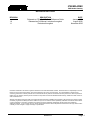
REVISION HISTORY
REVISION DESCRIPTION DATE
Released as 570-AG-HUB Quick Reference Guide January 2020
1.0 Released as Full Manual, revisions throughout August 2020
1.1 Revisions throughout November 2020
Information contained in this reference guide is believed to be accurate and reliable. However, Evertz assumes no responsibility for the use
thereof nor for the rights of third parties, which may be affected in any way by the use thereof. Any representations in this document
concerning performance of Evertz products are for informational use only and are not warranties of future performance, either expressed or
implied. The only warranty offered by Evertz in relation to this product is the Evertz standard limited warranty, stated in the sales contract or
order confirmation form.
Although every attempt has been made to accurately describe the features, installation and operation of this product in this reference guide,
no warranty is granted nor liability assumed in relation to any errors or omissions unless specifically undertaken in the Evertz sales contract
or order confirmation. Information contained in this reference guide is periodically updated and changes will be incorporated into
subsequent editions. If you encounter an error, please notify Evertz Customer Service department. Evertz reserves the right, without notice
or liability, to make changes in equipment design or specifications.

570EMR-ADMX
EMR Audio Gateway
Page - ii Revision 1.1
This page left intentionally blank

570EMR-ADMX
EMR Audio Gateway
Revision 1.1 Page - iii
TABLE OF CONTENTS
1. OVERVIEW ................................................................................................................................... 1
2. SPECIFICATIONS ......................................................................................................................... 3
2.1. AUDIO INPUTS .................................................................................................................... 3
2.2. ETHERNET INTERFACE ..................................................................................................... 3
2.3. ELECTRICAL ....................................................................................................................... 3
2.4. FRAMES ............................................................................................................................... 3
3. INSTALLATION ............................................................................................................................ 5
3.1. FRONT AND REAR PLATE ................................................................................................. 5
3.1.1. Front Plate ................................................................................................................. 5
3.1.2. Rear Plate .................................................................................................................. 5
3.2. HARDWARE INSTALLATION .............................................................................................. 5
4. CONFIGURING 570EMR THROUGH WEBEASY® ....................................................................... 7
4.1. SYSTEM ............................................................................................................................... 7
4.1.1. Control Port Configuration: ........................................................................................ 7
4.1.2. Data Port Configuration ............................................................................................. 8
4.1.3. Data Port Monitor ....................................................................................................... 8
4.1.4. SFP Control ............................................................................................................... 9
4.1.5. SFP Monitor ............................................................................................................... 9
4.1.6. Genlock Control ......................................................................................................... 9
4.1.7. InBand Control ......................................................................................................... 10
4.1.8. RPC Timeout ........................................................................................................... 10
4.1.9. Time Management ................................................................................................... 10
4.1.10. Card Control ............................................................................................................ 11
4.2. PRODUCT FEATURES ...................................................................................................... 11
4.2.1. Product Features ..................................................................................................... 11
4.2.2. License Control ........................................................................................................ 11
4.3. INPUT FLOW CONTROL ................................................................................................... 12
4.4. OUTPUT FLOW CONTROL ............................................................................................... 13
4.4.1. Global Control .......................................................................................................... 13
4.4.2. SFP Output .............................................................................................................. 13
4.4.3. Output flow Control .................................................................................................. 13
4.4.4. Output Flow Advanced Control ................................................................................ 14
4.5. FLOW MAPPING ................................................................................................................ 15
4.5.1. Global Control .......................................................................................................... 15
4.5.2. Flow Mapping .......................................................................................................... 15
4.6. DELAY CONTROL ............................................................................................................. 16
4.6.1. Global Delay Control ................................................................................................ 17
4.6.2. Per-Stream Delay Control and Monitor .................................................................... 17

570EMR-ADMX
EMR Audio Gateway
Page - iv Revision 1.1
4.7. PTP CONTROL .................................................................................................................. 18
4.7.1. PTP Control ............................................................................................................. 18
4.7.2. PTP Monitor ............................................................................................................ 18
4.7.3. PTP vs Genlock....................................................................................................... 19
4.8. REFERENCE NOTIFY ....................................................................................................... 19
4.8.1. Reference Notify...................................................................................................... 19
4.8.2. PTP Notify ............................................................................................................... 20
4.9. NOTIFY .............................................................................................................................. 20
4.10. SNMP TRAP ...................................................................................................................... 21
4.11. CONFIGURATION MANAGEMENT ................................................................................... 21
5. FIRMWARE UPGRADE .............................................................................................................. 23
5.1. FIRMWARE UPGRADE USING WEBEASY®..................................................................... 23
6. APPENDIX A .............................................................................................................................. 25
7. APPENDIX B .............................................................................................................................. 27

570EMR-ADMX
EMR Audio Gateway
Revision 1.1 Page - v
Figures
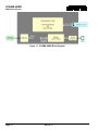
Figure 1-1: 570EMR-ADMX Block Diagram ............................................................................................ 2
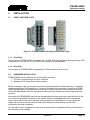
Figure 3-1: 570EMR-ADMX Front (left) and Rear Plate (right) ................................................................ 5
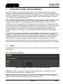
Figure 4-1: WebEASY® - System Tab / Control Port Configuration ......................................................... 7
Figure 4-2: WebEASY® - System Tab / Data Port Configuration ............................................................ 8
Figure 4-3: WebEASY® - System Tab / Data Port Monitor ..................................................................... 8
Figure 4-4: WebEASY® - System Tab / Data Port Configuration ............................................................ 9
Figure 4-5: WebEASY® - System Tab / SFP Monitor ............................................................................. 9
Figure 4-6: WebEASY® - System Tab / Genlock Control ........................................................................ 9
Figure 4-7: WebEASY® - System Tab / In-band Control ....................................................................... 10
Figure 4-8: WebEASY® - System Tab / RCP Timeout .......................................................................... 10
Figure 4-9: WebEASY® - System Tab / Time Management ................................................................. 10
Figure 4-10: WebEASY® - System Tab / Card Control ......................................................................... 11
Figure 4-11: WebEASY® - Product Features Tab ................................................................................. 11
Figure 4-12: WebEASY® - Input Flow Control / SFP Input ................................................................... 12
Figure 4-13: WebEASY® - Output Flow Control / Global Control .......................................................... 13
Figure 4-14: WebEASY® - Output Flow Control / SFP Output .............................................................. 13
Figure 4-15: WebEASY® - Output Flow Control / Output Flow Control ................................................. 14
Figure 4-16: WebEASY® - Output Flow Control / SFP Input ................................................................. 14
Figure 4-17: WebEASY® - Output Flow Control ................................................................................... 15
Figure 4-18: WebEASY® - Delay Control Tab ...................................................................................... 16
Figure 4-19: WebEASY® - PTP Control Tab ........................................................................................ 18
Figure 4-20: WebEASY® - Reference Notify Tab ................................................................................. 19
Figure 4-21: WebEASY® - Notify Tab ................................................................................................... 20
Figure 4-22: WebEASY® - SNMP Trap Tab ......................................................................................... 21
Figure 4-23: WebEASY® - Configuration Management Tab ................................................................. 21
Figure 5-1: WebEASY® - Upgrade Button on Top Menu Bar ................................................................. 23
Figure 5-2: WebEASY® - Firmware Upgrade Menu .............................................................................. 23
Figure 5-3: WebEASY® - Firmware Upgrade Menu .............................................................................. 24
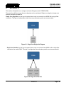
Figure 6-1: Single Core Single Hot Diagram ......................................................................................... 25
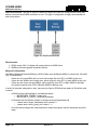
Figure 6-2: Single Core Dual Hot .......................................................................................................... 25
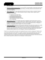
Figure 6-3: Dual Core Dual Hot ............................................................................................................ 26
Tables
Table 4-1: IP Output Flow Advanced Control (AES67) – Parameters ................................................... 14
Table 4-2: Output Flow Mapping Parameters ....................................................................................... 16
Table 4-3: WebEASY® - PTP Vs Genlock Tab ..................................................................................... 19

570EMR-ADMX
EMR Audio Gateway
Page - vi Revision 1.1
This page left intentionally blank

570EMR-ADMX
EMR Audio Gateway
Revision 1.1 Page - 1
1. OVERVIEW
The 570EMR-ADMX is Evertz 3rd generation low latency high-density IP audio shuffler card that enables
edge devices to shuffle audio on the mono level. This device is the core for the audio subsystem which
operates hand to hand with Magnum Audio Subsystem in 10GbE and 25GbE environment.
This device will operate in the background and user will not have access to it as a TX or RX device. It only
works over SFP1 as the main link and for redundancy, a second unit is required. This single fiber can
handle up 640 flows and the resources can be expanded beyond 640 by adding additional modules,
allowing 570EMR–ADMX to be used in small, medium or large–scale SDVN environments.
The 570EMR–ADMX is hot-swappable and monitored via VistaLINK® in any of the Evertz 570 modular
frames, it is strongly recommended to add a separate module for redundancy to avoid audio loss in case
of device failure.
This module supports Audio over IP for AES67 * (SMPTE ST 2010–30 Level A & B).
Features:
• AES67: maximum of 640 multicasts per port *
• SMPTE ST 2110–30 Level A & B
• Mono audio shuffling
• VistaLINK®–capable for remote monitoring, control and configuration capabilities via SNMP using
VistaLINK® PRO
• 1 x SFP+ 10GE trunk interfaces
• Supports PTP
• Supports AES67 audio over IP standards
• 1 x 10GE SFP+ Ports:
o SFP1 sends/receives AES67 streams.
• InBand Control:
o SFP1 is used for Main Inband Control.
* Check with factory on availability and for further details

570EMR-ADMX
EMR Audio Gateway
Page - 2 Revision 1.1
Figure 1-1: 570EMR-ADMX Block Diagram

570EMR-ADMX
EMR Audio Gateway
Revision 1.1 Page - 3
2. SPECIFICATIONS
2.1. AUDIO INPUTS
Number of MADI Inputs: 10 x DIN (Future use)
Number of MADI Outputs: 10 x DIN (Future use)
Connector: DIN 1.0/2.3
Impedance: 75 Ω terminating
2.2. ETHERNET INTERFACE
Number of SFP Ports: 1 x 10GE SFP+ (Remaining are for future development)
2.3. ELECTRICAL
Voltage: +12VDC
Power Consumption: 70W
2.4. FRAMES
Frame and Slot Occupancy: 570 Frame with 2 slot occupancy
570 Standalone Frame

570EMR-ADMX
EMR Audio Gateway
Page - 4 Revision 1.1
This page left intentionally blank

570EMR-ADMX
EMR Audio Gateway
Revision 1.1 Page - 5
3. INSTALLATION
3.1. FRONT AND REAR PLATE
Figure 3-1: 570EMR-ADMX Front (left) and Rear Plate (right)
3.1.1. Front Plate
The front plate of 570EMR-ADMX is equipped with 12 10GE SFP ports capable of passing/receiving 10GE
of data per port. Only the first 1 x 10GE SFP port is available for this application.
3.1.2. Rear Plate
The rear plate of 570EMR-ADMX is equipped with 20 DIN connectors for future use.
3.2. HARDWARE INSTALLATION
570EMR-ADMX can be installed in one of the following two ways:
1. 570 Frame communication via Frame Controller
2. Standalone 570 Frame (Direct Communication)
Before handling the card, it is important to minimize the potential effects of static electricity. It is therefore
recommended that an ESD strap be worn. Locate on the chassis two vacant slots. Unpack the 570EMR-
ADMX and separate the rear panel from the main card. Locate on the rear of the rack the two slots and
remove the blank panels. Insert the rear panel into the back of the chassis and secure using the screws
provided.
Now insert the 570EMR-ADMX card into the corresponding front slots ensuring the card lines up with the
slot runners on the bottom and the top of the chassis. Push the card firmly into the slot ensuring that
when it mates with the rear card it has been firmly pushed into a seated position. Do not connect any
cables to the rear card (failure to do this could cause unwanted network issues) until the initial
configuration has been completed.
This procedure can be completed to all the other modules and is hot-swappable allowing for the frame to
be powered on while installing.

570EMR-ADMX
EMR Audio Gateway
Page - 6 Revision 1.1
This page left intentionally blank

570EMR-ADMX
EMR Audio Gateway
Revision 1.1 Page - 7
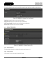
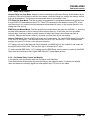
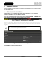
4. CONFIGURING 570EMR THROUGH WEBEASY®
The 570FC provides a built-in web interface that allows a user to interact with the 570FC as well as
WebEASY® supported products using a standard Internet web browser. The 570FC web interface can be
accessed by entering the IP address of the 570FC into the address bar of an Internet web browser. When
first visiting the 570FC web interface, the user will be asked to enter a Login and Password. Log in with
“root” as username and “evertz” as password.
The home page of the 570FC provides a list of all products currently under the control of the 570FC along
with a menu that displays information on specific Product Location, Hardware, Software, SNMP V1
Community strings, SNMP V1 Trap destinations and local TRAP Management Faults for the 570FC.
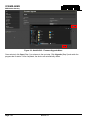
570EMR can receive IP address from 570FC through proxy mode. To receive the IP address from 570FC,
click “Software” tab from 570FC webpage and select the IP Configure Mode “Static or DHCP”. Then select
the “Slot#”, where you see the 570EMR in 570 Menu Page and “Enable” the Proxy Mode under the
selected Slot#, then it will display three fields to enter the IP Address, Netmask and Gateway. After
configuring these fields, click “Apply” to save the settings and refresh the page to see the settings are
saved.
Go back to 570FC home page, it will provide a list of all 570EMR currently in the frame. It will also provide
the firmware version of each card in the frame. Cards that appear in the white text do not support the
WebEASY® interface and are therefore not configurable through the web interface. These cards must be
configured using VistaLINK® or Serial Menu. Cards that support the WebEASY® interface will appear in
yellow. Clicking on the yellow product name which is linked to the controls available for that card.
Refresh, Apply, and Dynamic Apply buttons on top of the page are used to apply changes to the config
and refresh to check the current status of the config. These function in the same manner as in VistaLINK®.
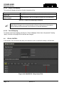
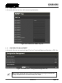
4.1. SYSTEM
This tab provides the basic configurations / Monitoring of IP address, InBand Control, Data Port Monitoring
and Reference.
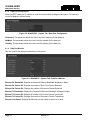
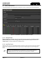
4.1.1. Control Port Configuration:
Figure 4-1: WebEASY® - System Tab / Control Port Configuration
Ethernet: Allows the user to set the IP Address, Netmask and Gateway. This IP Address is used for
control and monitor when 570EMR in a standalone frame.
Proxy: This IP Address is received from 570FC through proxy. Doesn’t allow the user to change the IP in
570EMR webpage, but user can change the IP Address in 570FC WebEASY page. This IP address is
used for control and monitor when 570EMR is in 570 Frame with 570FC.

570EMR-ADMX
EMR Audio Gateway
Page - 8 Revision 1.1
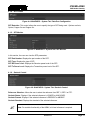
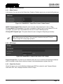
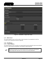
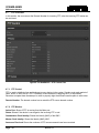
4.1.2. Data Port Configuration
Make sure SFP’s data port IP address is under the same subnet as Magnum data ports. This setting is
crucial for Magnum communication.
Figure 4-2: WebEASY® - System Tab / Data Port Configuration
IP Address: This parameter allows the user to set the IP Address for the data port.
NetMask: This parameter allows the user to set the netmask for the data port.
Gateway: This parameter allows the user to set the gateway for the data port.
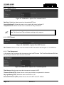
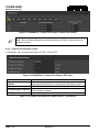
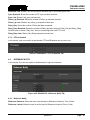
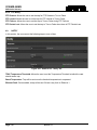
4.1.3. Data Port Monitor
User can monitor the data port parameters in the section.
Figure 4-3: WebEASY® - System Tab / Data Port Monitor
Ethernet Rx Bandwidth: Displays the Received Ethernet Bandwidth displayed in Mbps.
Ethernet Rx Frames Ok: Displays the number of Error-Free Frames Received.
Ethernet Rx Frames Err: Displays the number of Erroneous Frames Received.
Ethernet Tx Bandwidth: Displays the Transmitted Ethernet Bandwidth displayed in Mbps.
Ethernet Tx Frames Ok: Displays the number of Error-free Frames Transmitted.
Ethernet Tx Frames Err: Displays the number of Erroneous Frames Transmitted.
Ethernet Link Status: Displays the Ethernet port link status as either up or down.
Page is loading ...
Page is loading ...
Page is loading ...
Page is loading ...
Page is loading ...
Page is loading ...
Page is loading ...
Page is loading ...
Page is loading ...
Page is loading ...
Page is loading ...
Page is loading ...
Page is loading ...
Page is loading ...
Page is loading ...
Page is loading ...
Page is loading ...
Page is loading ...
Page is loading ...
Page is loading ...
-
 1
1
-
 2
2
-
 3
3
-
 4
4
-
 5
5
-
 6
6
-
 7
7
-
 8
8
-
 9
9
-
 10
10
-
 11
11
-
 12
12
-
 13
13
-
 14
14
-
 15
15
-
 16
16
-
 17
17
-
 18
18
-
 19
19
-
 20
20
-
 21
21
-
 22
22
-
 23
23
-
 24
24
-
 25
25
-
 26
26
-
 27
27
-
 28
28
-
 29
29
-
 30
30
-
 31
31
-
 32
32
-
 33
33
-
 34
34
-
 35
35
-
 36
36
-
 37
37
-
 38
38
-
 39
39
-
 40
40


evertz 570EMR‑ADMX User manual
- Category
- Supplementary music equipment
- Type
- User manual
Ask a question and I''ll find the answer in the document
Finding information in a document is now easier with AI
Related papers
-
evertz 570EMR‑AG‑HUB User manual
-
-
-
-
-
-
-
-
-
Other documents
-
 WW WOHLER iAM-MIX16 User manual
-
Wohler iAM-MIX16 Owner's manual
-
VMware Horizon Client 4.5 for Windows User guide
-
VMware Horizon Horizon Client 4.6 for Windows Installation guide
-
-
Lenovo THINKPAD X61 Deployment Manual
-
