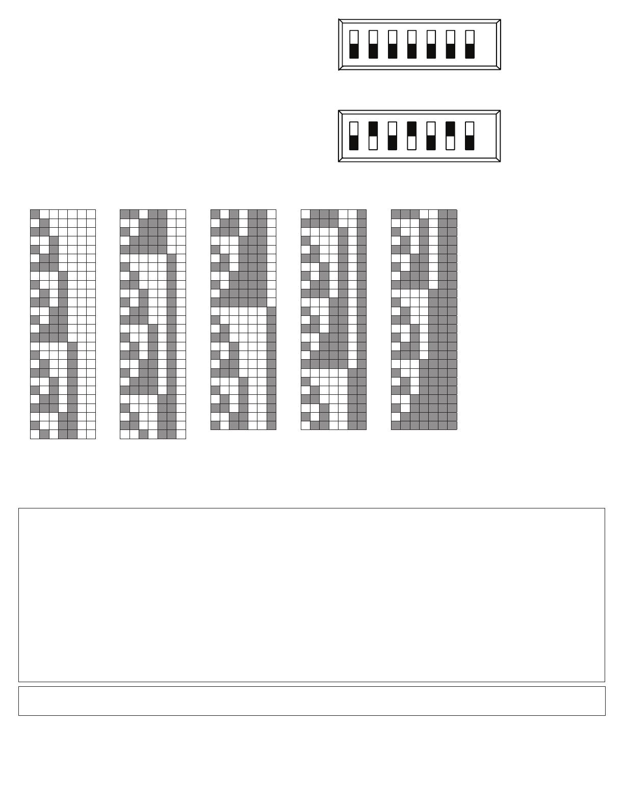
Potter PAD200-PHD User manual

Category
Smoke detectors
Type
User manual

This manual is also suitable for

1. Descripon



PAD200-PD & PAD100-PD: Photoelectric Smoke Detector
PAD200-PHD & PAD100-PHD: Photoelectric Smoke / Heat Detector
PAD200-PCD: Photoelectric Smoke / CO Detector
PAD200-PCHD: Photoelectric Smoke / CO Detector/ Heat Detector
PAD100-HD: Heat Detector
PAD100-CD: Carbon Monoxide Detector
2. Field Wiring Diagrams








3. Wiring Instrucon
 
 
 
NOTICE:

 
 
 
 
CAUTION!

Detector Base Mounng










 
 
 
NOTICE: 

 
 
 
 
 
 
NOTICE: 


4. Spacing Limitaons
NOTICE: 

PAD100-PD, PAD200-PD, PAD200-PCD, PAD200-PCHD, PAD100-PHD and
PAD200-PHD: Photoelectric Smoke Detector




PAD100-HD: Heat Detector


5. Tesng



NOTICE: 


S+
S-
S+
S-
To FACP
Loop (SLC) First Detector Base Last Detector Base
Figure 1: Wiring (Style B)

Alarm Set-Point Rate of Rise Spacing Fixed Temperature Spacing

  

  

  

 
Detector Bases:
PAD100-6DB & PAD100-4DB
Detectors:
PAD100-PD, PAD100-PHD, PAD200-PD, PAD200-PHD,
PAD200-PCD, PAD200-PCHD, PAD100-HD and PAD100-CD
FIGURE 2: Assembly of Detector

Operaonal Tesng




NOTICE:

Sensivity Tesng
(Dirty Value Read / Print)


NOTICE: 


Funconal Tesng
NOTICE:




Walk Test



CAUTION!

 



 

NOTICE:

 
CAUTION:oo
 
  
 
 
  
  
 



NOTICE:


6. Maintenance




NOTICE:
 
 
 
 
 
 
 


  


  
 
steps to remove dust on the detector
 
 
  
 
  
NOTICE: 

 


 







 


 


 
NOTICE: 

FIGURE 3: Removing Detector Cover (PD models only)
Remove the two screws
(T10) on back of detector
to remove detector cover.
NOTICE: DO NOT USE A
POWER DRIVER WHEN
REMOVING /
INSTALLING SCREWS.
PAD200-PD shown
Line up pins on
circuit board base to
pin holes on optic
cage base.
NOTICE: DO NOT
REMOVE THE OPTIC
CAGE OR METAL
BUG SCREEN THAT IS
AROUND THE OPTIC
CAGE.
NOTICE: AVOID
TOUCHING CIRCUIT
BOARD. WHEN
CLEANING IS
NEEDED, USE CLEAN
COMPRESSED AIR.
PAD200-PD shown
FIGURE 4: Remove Optic Cage Base from Detector for Cleaning (PD models only)
Line up pin holes on
optic cage base to pins
on circuit board base.
PAD200-PD shown
FIGURE 5: Pin Holes on Back of Optic Cage Base (PD models only)
7. Locking Feature



 



 
 
8. Detector Base Opons
NOTE:
Installaon instrucons for PAD100-DUCTR, reference docment
number 5406321-A.
Installaon instrucons for PAD100-DUCT, reference document
number 5406322-A.
Installaon instrucons for PAD200-DUCTR, reference docment
number 5406429-A.
Installaon instrucons for PAD200-DUCT, reference document
number 5406428-A.
9.
Detector will not operate without electrical power. Fire can cause
power interrupon, discuss with a re protecon specialist for
addional safeguards.
Do not open PAD100-PHD, PAD200-PHD, PAD100-HD PAD200-PCD,
PAD200-PCHD, or PAD100-CD
detector for cleaning. If the detector is opened, product warranty
becomes void.
If the detector does not work properly, do not try and x it yourself.
This will void your warranty. For techincal assistance, contact
Poer Electric Signal Company at 866-956-1211 for instrucons to
return a detector that does not operate properly.
Detector will not sense res that start in areas where smoke or heat
cannot reach the detector. Smoke or heat from res in walls, roofs
or on the opposite side of closed doors may not reach the detector.
Keep supplied dust cover in place during installaon and construcon.
Remove dust cover prior to operaon.
Dust cover is not a substute for removal of detector during new
construcon or remodeling.
The detector cannot detect smoke when the dust cover is in place.
Never use an open ame of any kind to test your device. You may
ignite and damage the detector.
Do not cover, tape or otherwise block the openings of your detector.
The openings are designed to allow air to pass through the detector,
thus sampling the air around the detector.
Detectors are not to be used with detector guards unless the
combinaon has been evaluated by a naonally recognized tesng
laboratory and found suitable for that purpose.
To ensure proper operaon, store detector within the
recommended ranges. Allow the detector to stabilize to room
temperature before applying power.
If the detector ever fails to test properly, replace it immediately.
Products under warranty may be returned to the manufacturer for
replacement, see LIMITED WARRANTY.
For technical assistance, contact Poer Electrical Signal Company at
1-866-956-1211
WARNING
!
FIGURE 6: Locking Feature


to remove detector

FIGURE 7: Disable Locking Feature


Model Descripon
 
 
 

 

 

 

 

10c. Specicaons / Rangs for Use with Detector Bases: PAD100-6DB, PAD100-4DB
No. Item PAD100-6DB PAD100-4DB
  
  
   


  
  
5 
* The standby current is the current that the device consumes when the device is in a non-activated condition and where no communication current is transmitted to the FACP.
** Reference spacing requirements in Section 4.
10a. Specications / Ratings for Use with Detectors: PAD100-PD, PAD200-PD, PAD200-PCD, PAD200-PCHD, PAD100-PHD and PAD200-PHD
No. Item PAD100-HD PAD100-CD
1Working Voltage Range 24 VDC
2 Standby Current (*) 300 µA
3 Alarm Indicator 1 LED
4 Alarm Indictor Current 1.4 mA
5 Alarm Set-Point Range (**) 135O to 174O F
(57O to 79O C)
175O to 185O F
(80O to 85O C)
135O to 160O F
(57O to 71O C) Fixed 70, 150, 400 PPM
6Installation Temperature Range 32O to 100O F
(0O to 38O C)
32O to 150O F
(0O to 66O C)
32O to 100O F
(0O to 38O C) 32O to 100O F (0O to 38O C)
7 Operating Relative Humidity Range 0% to 93% (non-condensing)
8Start-up Time 1 second
9 Maximum Number of Addresses per SLC Loop 127
10 Maximum Number of Lighted
Indicators in Alarm per SLC Loop 30
11 Weight (without base) 82 g (2.89 oz) 92 g (3.25 oz)
12 Dimensions
(without base)
Height 1.94 in (49 mm) 1.43 in (36 mm)
Diameter 3.93 in. (100 mm)
13 Approvals / Listings ANSI/UL 521 ANSI/UL 2075
14 Permitted Mounting Location(s) Ceiling, Wall
10b. Specications / Ratings for Use with Detectors: PAD100-CD , PAD100-HD
No. Item PAD100-PD PAD100-PHD PAD200-PCD PAD200-PCHD PAD200-PD PAD200-PHD
1Working Voltage Range 24 VDC
2 Standby Current (*) 300 µA
3 Alarm Indicator 1 LED
4 Alarm Indictor Current 1.4 mA
5 Smoke Sensitivity Range (**) 1.0-3.7 %/ft.
(3.2-11.6%/m)
1.0-3.7 %/ft.
(3.2-11.6%/m) /
135O to 174OF
(57O to 79O C)
1.1-3.5 %/ft.
(3.6-11%/m)
1.1-3.5 %/ft.
(3.6-11%/m) /
135O to 174OF
(57O to 79O C)
1.1-3.5 %/ft.
(3.6-11%/m)
1.1-3.5 %/ft.
(3.6-11%/m) /
135O to 174OF
(57O to 79O C)
6Installation Temperature Range 32O to 120O F
(0O to 49O C)
32O to 115O F
(0O to 46O C)
32O to 120O F
(0O to 49O C)
32O to 115O F
(0O to 46O C)
32O to 120O F
(0O to 49O C)
32O to 115O F
(0O to 46O C)
7 Operating Relative Humidity Range 0% to 93% (non-condensing)
8Start-up Time 1 second
9 Maximum Number of Addresses per SLC Loop 127
10 Maximum Number of Lighted
Indicators in Alarm per SLC Loop 30
11 Weight (without base) 110.5 g (3.9 oz) 116 g (4.1 oz) 113 g (4.0 oz) 118.5 g (4.2 oz) 110.5 g (3.9 oz) 116 g (4.1 oz)
12 Dimensions
(without base)
Height 1.35 in (34 mm) 1.94 in (49 mm) 1.35 in (34 mm) 1.94 in (49 mm) 1.35 in (34 mm) 1.94 in (49 mm)
Diameter 3.93 in. (100 mm)
13 Approvals / Listings ANSI/UL 268 6th
edition
ANSI/UL 268 6th
edition,
ANSI/UL 521 7th
edition
ANSI/UL 268 7th
edition,
ANSI/UL 2075 4th
edition
ANSI/UL 268 7th
edition,
ANSI/UL 521 7th
edition, ANSI/UL
2075 4th edition
ANSI/UL 268 7th
edition
ANSI/UL 268 7th
edition,
ANSI/UL 521 7th
edition
14 Permitted Mounting Location(s) Ceiling, Wall
11. PAD Protocol Dip Switch Sengs



Seng the Address: 


seven
(7) posion dip switch






124816 32 64
ON
OFF
FIGURE 8: Enlarged View of PAD Device with
Dip Switch Setting Unaddressed



124816 32 64
ON
OFF
FIGURE 9: Enlarged View of PAD Device with
Dip Switch Setting Addressed







FIGURE 10: PAD Device Dip Switch Addresses Table (Addresses 1-127)
      
5

















      
      


























      
      


55






















      
      

























      
      

























      
Potter Electric Signal Company, LLC
1609 Park 370, Hazelwood, MO 63042
Phone: 800-325-3936
www.pottersignal.com
Important Notice:
These materials have been prepared by Potter Electrical Signal Company, LLC (“Potter”) for informational purposes only, are necessarily summary, and are not purported to serve as legal advice and should not be used as such. Potter makes no representations and warranties, express or implied, that these materials are complete and accurate,
up-to-date, or in compliance with all relevant local, state and federal laws, regulations and rules. The materials do not address all legal considerations as there is inevitable uncertainty regarding interpretation of laws, regulations and rules and the application of such laws, regulations and rules to particular fact patterns. Each person’s activities
can differently affect the obligations that exist under applicable laws, regulations or rules. Therefore, these materials should be used only for informational purposes and should not be used as a substitute for seeking professional legal advice. Potter will not be responsible for any action or failure to act in reliance upon the information
contained in this material.
Manual Number:
550-0622-AAE
Manual Issue Date:
03/01/16
LIMITED WARRANTY
For a period of 60 months from the date of manufacture (or as long as required by applicable law), Potter Electric Signal Company, LLC warrants to you the original purchaser that the appliance described in this product
information booklet will be free from defects in workmanship and materials under normal use and service.
This warranty does not apply and is void if damage or failure is caused by: accident, abuse, misuse, abnormal use, faulty installation, liquid contact, re, earthquake or other external cause; operating the appliance outside
Potter Electric Signal Company, LLCs published guidelines; or service, alteration, maintenance or repairs performed by anyone other than Potter Electric Signal Company, LLC. This warranty does not transfer to subsequent
owners or purchasers of this appliance. This warranty also does not apply to: consumable parts, such as batteries; cosmetic damage, including but not limited to scratches or dents; defects caused by normal wear and tear or
otherwise due to the normal aging of the appliance, or if any serial number has been removed or defaced from the appliance.
TO THE EXTENT PERMITTED BY LAW, THIS WARRANTY AND THE REMEDIES SET FORTH HEREIN ARE EXCLUSIVE AND IN LIEU OF ALL OTHER WARRANTIES, REMEDIES AND CONDITIONS, WHETHER ORAL, WRITTEN, STATUTORY,
EXPRESS OR IMPLIED. POTTER ELECTRIC SIGNAL COMPANY, LLC DISCLAIMS ALL STATUTORY AND IMPLIED WARRANTIES, INCLUDING WITHOUT LIMITATION, WARRANTIES OF MERCHANTABILITY AND FITNESS FOR A PARTICULAR
PURPOSE AND WARRANTIES AGAINST HIDDEN OR LATENT DEFECTS TO THE EXTENT PERMITTED BY LAW. TO THE EXTENT SUCH WARRANTIES CANNOT BE DISCLAIMED, AND TO THE EXTENT PERMITTED BY APPLICABLE LAW, SUCH
IMPLIED WARRANTIES SHALL APPLY ONLY FOR THE WARRANTY PERIOD SPECIFIED ABOVE. PLEASE NOTE THAT SOME STATES (COUNTRIES AND PROVINCES/TERRITORIES) DO NOT ALLOW LIMITATIONS ON HOW LONG AN IMPLIED
WARRANTY (OR CONDITION) LASTS. SO THE ABOVE LIMITATION MAY NOT APPLY TO YOU. EXCEPT AS PROVIDED IN THIS WARRANTY AND TO THE EXTENT PERMITTED BY LAW, POTTER ELECTRIC SIGNAL COMPANY, LLC WILL NOT BE
LIABLE FOR ANY DIRECT, SPECIAL, INCIDENTAL OR CONSEQUENTIAL DAMAGES RESULTING FROM ANY BREACH OF WARRANTY OR CONDITION, OR ARISING IN CONNECTION WITH THE SALE, USE OR REPAIR OF THE APPLIANCE, OR
UNDER ANY OTHER LEGAL THEORY, INCLUDING BUT NOT LIMITED TO LOSS OF USE, LOSS OF REVENUE, LOSS OF ACTUAL OR ANTICIPATED PROFITS, LOSS OF THE USE OF MONEY, LOSS OF BUSINESS, LOSS OF OPPORTUNITY, LOSS OF
GOODWILL, AND LOSS OF REPUTATION. THE MAXIMUM LIABILITY OF POTTER ELECTRICAL SIGNAL COMPANY, LLC SHALL NOT IN ANY CASE EXCEED THE PURCHASE PRICE PAID BY YOU FOR THE APPLIANCE. PLEASE NOTE THAT SOME
STATES (COUNTRIES AND PROVINCES/TERRITORIES) DO NOT ALLOW THE EXCLUSION OR LIMITATION OF DIRECT, INCIDENTAL OR CONSEQUENTIAL DAMAGES, SO THE ABOVE LIMITATION OR EXCLUSION MAY NOT APPLY TO YOU.
If a defect in workmanship or materials causes your appliance to become inoperable within the warranty period, you must return the appliance to Potter Electric Signal Company, LLC postage prepaid to: Potter Electric Signal
Company, LLC, 1609 Park 370, Hazelwood MO 63042. You must prove to the satisfaction of Potter Electric Signal Company, LLC the date of purchase of your appliance. You must also enclose a return address. Warranty service may
only be performed by Potter Electric Signal Company, LLC personnel at Potter Electric Signal Company, LLC’s facilities in Hazelwood, Missouri. You must also pack the appliance to minimize the risk of it being damaged in transit. If we
receive an appliance in a damaged condition as the result of shipping, we will notify you and you must seek a claim with the shipper.
If you submit a valid claim to Potter Electric Signal Company, LLC during the warranty period, Potter Electric Signal Company, LLC will, at its option, repair your appliance or furnish you with a new or rebuilt appliance
without charge to you except for postage required to return the appliance to us. Potter Electric Signal Company, LLC will not reimburse you for repairs or replacement parts provided by other parties. Your repaired or
replacement appliance will be returned to you free of charge and it will be covered under the warranty for the balance of the warranty period, if any. When a product or part is replaced, any replacement item becomes your
property and the replaced item becomes property of Potter Electric Signal Company, LLC. For additional warranty and product information go to www.pottersignal.com.
THIS WARRANTY GIVES YOU SPECIFIC LEGAL RIGHTS AND YOU MAY ALSO HAVE OTHER RIGHTS WHICH VARY FROM STATE TO STATE (OR BY COUNTRY OR PROVINCE/TERRITORY). BY THIS WARRANTY, POTTER ELECTRIC
SIGNAL COMPANY, LLC DOES NOT LIMIT OR EXCLUDE YOUR RIGHTS EXCEPT AS ALLOWED BY LAW. TO FULLY UNDERSTAND YOUR RIGHTS, YOU SHOULD CONSULT THE LAWS OF YOUR COUNTRY, PROVINCE/TERRITORY OR STATE.
  • Page 1 1
  • Page 2 2
  • Page 3 3
  • Page 4 4
  • Page 5 5

Potter PAD200-PHD User manual

Category
Smoke detectors
Type
User manual
This manual is also suitable for

Ask a question and I''ll find the answer in the document

Finding information in a document is now easier with AI