Harbor Freight Tools 92464 User manual
- Category
- Power tools
- Type
- User manual

Power INVerTer
2,000 waTT / 4,000 waTT Peak
ASSEMBLY AND OPERATING INSTRUCTIONS
3491 Mission Oaks Blvd., Camarillo, CA 93011
Visit our Web site at http://www.harborfreight.com
Copyright
©
2004 by Harbor Freight Tools
®
. All rights reserved. No portion
of this manual or any artwork contained herein may be reproduced in any shape or
form without the express written consent of Harbor Freight Tools.
For technical questions and replacement parts, please call 1-800-444-3353
TO PREVENT SERIOUS INJURY,
READ AND UNDERSTAND ALL WARNINGS
AND INSTRUCTIONS BEFORE USE.
92464

SKU 92464 Page 2
For technical questions, please call 1-800-444-3353.
Save This Manual
You will need the manual for the safety warnings and precautions, assembly
instructions, operating and maintenance procedures, parts list and diagram. Keep
your invoice with this manual. Write the invoice number on the inside of the front
cover. Keep the manual and invoice in a safe and dry place for future reference.
Safety Warnings and Precautions
WARNING: When using this device, basic safety precautions should always be
followed to reduce the risk of personal injury and damage to equipment.
Read all instructions before using this tool!
1. Do not plug in a battery charger if the charger has a warning that dangerous
voltages are present at the battery terminals.
2. Keep work area clean. Cluttered areas invite injuries.
3. Keep inverter away from any direct heat source or combustible material.
4. Observe work area conditions. Do not use machines or power tools in damp
or wet locations. Don’t expose to rain. Keep work area well lighted. Do not
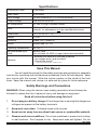
Specifications
Continuous Power 2,000 Watts
Peak Power 4,000 Watts
Input Voltage 12 Volts Nominal DC (11-15 Volts possible)
Output Voltage 120 Volts AC at 60 Hz
AC Receptacles (2) Two 3-Prong, Polarized Outlets
Fuse
30 Amps, 8 Qty.
(internal, for replacement only by a qualified technician)
Dimensions 14” L x 9” W x 3-
1
/
2
” H
Weight 11.6 lb.
Indicators Green LED = power on
Switch Rocker type, On / Off
Operating Temperature 30-105° F
Recommended Input
Cord
Battery cable
(not included; #2 AWG or larger cables recommended)
Features
- Modified sine wave with overload protection
- Low voltage alarm
1
and shutdown
2
- Overvoltage shutoff
3
1 at 10.5 V; 2 at about 10 V; 3 at about 15 V
REV 03/05

SKU 92464 Page 3
For technical questions, please call 1-800-444-3353.
use electrically powered tools in the presence of flammable gases or liquids.
5. Keep children away. Children must never be allowed in the work area. Do
not let them handle machines, tools, or extension cords.
6. Store idle equipment. When not in use, tools must be stored in a dry location
to inhibit rust. Always lock up tools and keep out of reach of children.
7. Use the right tool for the job. Do not attempt to force a small tool or attach-
ment to do the work of a larger industrial tool. There are certain applications
for which this tool was designed. It will do the job better and more safely at the
rate for which it was intended. Do not modify this tool and do not use this tool
for a purpose for which it was not intended.
8. Dress properly. Do not wear loose clothing or jewelry as they can be caught
in moving parts. Protective, electrically nonconductive clothes and nonskid
footwear are recommended when working. Wear restrictive hair covering to
contain long hair.
9. Use eye protection. Always wear ANSI approved impact safety goggles when
using tools.
10. Do not overreach. Keep proper footing and balance at all times. Do not reach
over or across running machines.
11. Maintain tools with care. Keep tools sharp and clean for better and safer
performance. Follow instructions for changing accessories. Inspect tool cords
periodically and, if damaged, have them repaired by an authorized techni-
cian.
12. Disconnect power. Unplug inverter when not in use.
13. Avoid unintentional starting. Be sure the switch is in the Off position when
not in use and before plugging in any appliance.
14. Stay alert. Watch what you are doing, use common sense. Do not operate any
tool when you are tired.
15. Check for damaged parts. Before using any tool, any part that appears
damaged should be carefully checked to determine that it will operate properly
and perform its intended function. Check for alignment and binding of moving
parts; any broken parts or mounting fixtures; and any other condition that may
affect proper operation. Any part that is damaged should be properly repaired
or replaced by a qualified technician. Do not use the tool if any switch does not
turn On and Off properly.
16. Servicing. This device should be serviced only by a qualified technician. This
item does not have any user-replaceable parts.

SKU 92464 Page 4
For technical questions, please call 1-800-444-3353.
17. Guard against electric shock.
Do not open the metal case; risk of electric shock.
Prevent body contact with grounded surfaces such as pipes, radia-
tors, ranges, and refrigerator enclosures during installation.
Connect all wires securely and cover the connections with insulat-
ing rubber boots (not included).
Store tools and metal objects away from the inverter.
18. Do not operate tool if under the influence of alcohol or drugs. Read warning
labels on prescriptions to determine if your judgment or reflexes are impaired
while taking drugs. If there is any doubt, do not operate the tool.
19. People with pacemakers should consult their physician(s) before using
this product. Electromagnetic fields in close proximity to a heart pacemaker
could cause interference to or failure of the pacemaker.
20. Keep the Inverter well-ventilated. Do not place any objects on top of or next
to the Inverter or allow anything to cover the cooling fans; doing so can cause
the Inverter to overheat, causing a potential fire hazard and/or damage to the
Inverter. Leave adequate ventilation space underneath the Inverter as well;
thick carpets or rugs can obstruct air flow, causing the Inverter to overheat.
21. Read and adhere to all warnings and safety precautions in the owner’s
manual for the device that this inverter is used to power.
22. A vehicle’s engine must never be used in any sealed structure. Carbon
monoxide is produced during operation and is DEADLY in a closed en-
vironment. Early signs of carbon monoxide poisoning resemble the flu, with
headaches, dizziness, or nausea. If you have these signs, get fresh air imme-
diately.
Note: Performance of this unit may vary depending on the available battery power
or appliance wattage.
Warning: The warnings, cautions, and instructions discussed in this instruction
manual cannot cover all possible conditions and situations that may occur.
It must be understood by the operator that common sense and caution are
factors which cannot be built into this product, but must be supplied by the
operator.
Unpacking
When unpacking, check to make sure that the Inverter is in good condition.
If any parts are missing or broken, please call Harbor Freight Tools at the number
on the cover of this manual as soon as possible.

SKU 92464 Page 5
For technical questions, please call 1-800-444-3353.
Connection
For the power inverter to work properly, your power source must provide 12 volts
DC, and the power source must provide enough current (i.e., 46 amps to operate
the load of 560 Watts or under).
Caution: This inverter must only be connected to batteries with a nominal
output voltage of 12 volts. Lower voltage will not operate the inverter properly,
and more voltage could damage the inverter or the device being powered. If
more than one 12 volt battery is to be used, the batteries must be connected
in a parallel circuit; batteries connected in a series circuit will produce too
much voltage.
1. Place the Power Inverter on a flat surface. Make sure it has adequate ventilation
and is not in direct sunlight. Fasten the inverter securely to the surface, using
screws or some other means. If holes are to be drilled, follow safe, proper
installation techniques.
2. Connect the Battery Cable (not included; #2 AWG or larger cables recommended)
lugs to the (Positive) red and (Negative) black terminals on the back of the
Inverter, see BACK above. Connect the Ground Cable (not included; #4 AWG
or larger cable recommended) lug to the Ground terminal, see BACK above.
Securely tighten.
3. The Power Inverter can be used either while the engine is running or off.
Connect the Battery Cables (not included) to the Negative (black) and Positive
(red) terminals of the battery.
4. Connect the Ground Cable to the appropriate location below:
a. If this unit is mounted within a vehicle with a grounded metal chassis,
attach the Ground Cable to a nearby location on the chassis.
b. If this unit is mounted in a boat or vehicle with an ungrounded chassis,
attach the Ground Cable to the vehicle’s grounding system.
c. ONLY if this unit is being used outside a vehicle,
attach the Ground Cable to the Negative Terminal of the Inverter.
BACK
NegativeGround Positive
WARNING!
Risk of Fire!
The positive battery
terminal connection
must be the LAST
connection and must
be done with the in-
verter’s switch off.
REV 06/06

SKU 92464 Page 6
For technical questions, please call 1-800-444-3353.
Maintenance
1. Keep this unit clean and dry. Unplug the unit before cleaning. Clean only the
outside of this unit with a soft, dry cloth; never clean this unit with water or harsh
cleaners.
2. This device does not contain any user replaceable parts. If it needs service,
take it to a qualified technician.
Due to the sensitive wiring and electrical circuits within this device, and the
possibility of injury, the fuses inside this unit are to be replaced only by a qualified
technician.
Fuses are included only for replacement by a technician.
Operation
Warning: NEVER operate this inverter unless it is properly grounded.
1. Open the rubber cover on the receptacle(s) and plug the 115 VAC device(s)
you wish to power into the 3-prong AC Receptacles. See FRONT above. The
appliance(s) must not use more than 2,000 (total) watts during continuous
operation, otherwise it may overload the Inverter.
Caution: Some rechargeable appliances may damage the Power Inverter or
the appliance. When first using a rechargeable device, check the inverter’s
temperature for the first 10 minutes. If it becomes abnormally hot, do not use
this device with the Inverter.
2. Flip the Power Switch to the On (I) position to turn on. Do not use the appliance
until the green power LED indicator is on.
3. Turn on appliance. If an alarm sound is heard, turn off the appliance.
Caution: It is recommended that the vehicle be started every hour to recharge
the battery system. Doing this will help prevent any unexpected shutdown
of the equipment. This will also help ensure that there will be enough battery
power to start the vehicle. Due to the risk of carbon monoxide inhalation (see
Warning # 22 on page 4), do not run the vehicle’s engine within an enclosed
area.
4. After use, disconnect the appliances, flip the Power Switch to the Off (O) position,
and put the rubber covers back in place over the receptacles.
FRONT
Outlets (covered)
Power
Indicator
Switch

SKU 92464 Page 7
For technical questions, please call 1-800-444-3353.
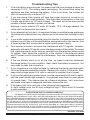
Troubleshooting Tips
1. If the low battery alarm sounds, this means that the input voltage is below the
necessary 10.5 V. The battery needs recharging. You should stop using the
appliance and then recharge the battery. If this is not done, the Inverter will
shut off automatically at around 10 V.
2. If you are unsure if the inverter will have the proper amount of current to run
the device, use this rough guideline: Take the power consumption of the load
in watts and divide it by 12 (input voltage). The result will be the approximate
number of amps needed to power your device.
Example: Load is rated at 312 watts. 312 watts / 12 V = 26 amps needed. You
could use this device with the inverter.
3. If your television will not start, it is important to keep in mind that some appliances
(including many televisions) may require two to six times their wattage to start
up.
4. If your audio system buzzes while using this inverter, it is because some sound
systems can not filter out the modified sine wave produced by the inverter. Use
a sound system that incorporates a higher quality power supply.
5. This inverter is made to minimize the interference with TV signals. However,
especially with weak TV signals, some interference may still be visible. To correct
this, place the inverter as far away as possible from the television antenna and
it’s cables. Next, adjust the orientation of the inverter to the antenna cables
and TV power cord to minimize the interference. Also use a shielded antenna
cable.
6. If the low battery alarm is on all the time, try these corrective measures:
Recharge battery if in poor condition. Next, check the battery connection. You
may need to clean the connectors.
7. If you are getting a low output voltage, try reducing the load to minimize watts.
You may have overloaded the inverter. Reduce your load to 1,900 watts. Also,
keep input voltage above 10.5 volts to maintain a constant flow of power.
8. If you are not getting any power output, turn the power switch Off and On again,
until the green power light comes on. Your devices may draw too much power
to operate them. The inverter may be in thermal shutdown. Let it cool down
and make sure there is adequate ventilation around the unit.
9. If the green light turns red, one of the following has happened:
A. Input voltage is too low. B. input voltage too high C. Short circuit D. Inverter
is near overload.
REV 03/05; 12/05 03/06
PLEASE READ THE FOLLOWING CAREFULLY
THE MANUFACTURER AND/OR DISTRIBUTOR HAS PROVIDED THE PARTS DIAGRAM IN THIS
MANUAL AS A REFERENCE TOOL ONLY. NEITHER THE MANUFACTURER NOR DISTRIBUTOR MAKES
ANY REPRESENTATION OR WARRANTY OF ANY KIND TO THE BUYER THAT HE OR SHE IS QUALIFIED
TO MAKE ANY REPAIRS TO THE PRODUCT OR THAT HE OR SHE IS QUALIFIED TO REPLACE ANY PARTS
OF THE PRODUCT. IN FACT, THE MANUFACTURER AND/OR DISTRIBUTOR EXPRESSLY STATES THAT
ALL REPAIRS AND PARTS REPLACEMENTS SHOULD BE UNDERTAKEN BY CERTIFIED AND LICENSED
TECHNICIANS AND NOT BY THE BUYER. THE BUYER ASSUMES ALL RISK AND LIABILITY ARISING
OUT OF HIS OR HER REPAIRS TO THE ORIGINAL PRODUCT OR REPLACEMENT PARTS THERETO, OR
ARISING OUT OF HIS OR HER INSTALLATION OF REPLACEMENT PARTS THERETO.

SKU 92464 Page 8
For technical questions, please call 1-800-444-3353.
REV 03/05
Assembly Diagram
NOTE: Some parts are listed and shown for illustration
purposes only and are not available individually
as replacement parts.
Parts List
Part Description Q’ty
1 Housing 1
2 PCB Board 1
3 Back Panel 1
4 Front Panel 1
5 Bottom Panel 1
6 Radiator 2
7 PCB Board 2 1
8 PVC Cover 1
9 Adapter 34 8
10 Wire 164mm 5
11 MOS 20
12 Adapter Circle 2
Part Description Q’ty
13 Capacitor 16.5mm 8
14 Fuse 8
15 Capacitor 22.4mm 2
16 Sheet Lock 2
17 Rubber Sheet 2
18 M3x12 Bolt Washer 6
19 M3x12 Bolt 6
20 M3x12 Bolt 4
21 M3x30 Bolt 4
22 M3x25 Bolt 8
23 Large MOS 8
24 Rubber Sleeve 8
Part Description Q’ty
25 Capacitor 11mm 1
26 Insulation Sleeve 2
27 Terminal 2
28 Fan 60x60x25 1
29 Fan 40x40x20 2
30 Hexagon Thin Nut 12
32 Socket 2
33 Switch 1
34 Led 5.0 1
35 Rd. Head Screw M4x8 4
36 Rec’d Pan Hd. Screw 8
-
 1
1
-
 2
2
-
 3
3
-
 4
4
-
 5
5
-
 6
6
-
 7
7
-
 8
8


Harbor Freight Tools 92464 User manual
- Category
- Power tools
- Type
- User manual
Ask a question and I''ll find the answer in the document
Finding information in a document is now easier with AI
Related papers
-
Chicago Electric 92708 User manual
-
-
Harbor Freight Tools 92688 User manual
-
-
-
CEN-TECH cen-tech 96706 User manual
-
-
-
-
Other documents
-
-
 Centech 60601 Owner's Manual & Safety Instructions
-
-
-
-
-
AIMS Power PWRB2500W User manual
-
-
-
