
a
BF50, BF50A, BF60, BF60A,
BF60CP, BF60CPA, BF70,
BF70A, BF75, BF85, BF85A
e
Exhaust Fan User’s Guide
210572116 Rev. B 5-06
Item Stock Number(s): BF50, BF50A, BF60, BF60A, BF60CP, BF60CPA,
BF70, BF70A, BF75, BF85, BF85A
READ AND SAVE THESE INSTRUCTIONS
READ CAREFULLY BEFORE ATTEMPTING TO ASSEMBLE, INSTALL, OPERATE OR MAINTAIN THE PRODUCT DESCRIBED.
PROTECT YOURSELF AND OTHERS BY OBSERVING ALL SAFETY INFORMATION. FAILURE TO COMPLY WITH
INSTRUCTIONS COULD RESULT IN PERSONAL INJURY AND/OR PROPERTY DAMAGE!
RETAIN INSTRUCTIONS FOR FUTURE REFERENCE.
GENERAL SAFETY INFORMATION
When using electrical appliances, basic precautions should always be followed to reduce
the risk of fire, electric shock and injury to person, including the following:
1. Read all instructions before installing or using exhaust fan.
2. Use this unit only in the manner intended by the manufacturer.
If you have questions, contact the manufacturer.
3. Before servicing or cleaning the unit, switch power off at
service panel and lock the service disconnecting means to
prevent power from being switched on accidentally. When the
service disconnecting means cannot be locked, securely fasten
a prominent warning device, such as a tag, to the service
panel.
SAVE THESE INSTRUCTIONS
IMPORTANT INSTRUCTIONS -
OPERATING MANUAL
4. Installation work and electrical wiring must be done by qualified
person(s) in accordance with all applicable codes and
standards, including fire-related construction.
5. Sufficient air is needed for proper combustion and exhausting
of gases through the flue (chimney) of fuel burning equipment to
prevent back drafting. Follow the heating equipment
manufacturer’s guideline and safety standards such as those
published by the National Fire Protection Association (NFPA)
and the American Society for Heating, Refrigeration, and Air
Conditioning Engineers (ASHRAE), and the local code authorities.
1 of 4
www.geelectrical.com

210572116 Rev. B 5-06
GENERAL SAFETY INFORMATION
(Continued)
CAUTION: FOR GENERAL VENTILATING USE ONLY. DO NOT
USE TO EXHAUST HAZARDOUS OR EXPLOSIVE MATERIALS AND
VAPORS.
6. When cutting or drilling into wall or ceiling, do not damage electrical
wiring and other hidden utilities.
7. Ducted fans must always be vented to the outdoors.
8. This unit must be grounded.
9. To avoid motor bearing damage and noisy and/or unbalanced
impellers, keep drywall spray, construction dust, etc. off power unit.
WARNING: TO REDUCE THE RISK OF FIRE, ELECTRIC SHOCK,
DO NOT USE THIS FAN WITH ANY SOLID-STATE SPEED CONTROL DEVICE.
10. Acceptable for use over a bathtub or shower when installed in a
GFCI protected branch circuit.
11. NEVER place a switch where it can be reached from a tub or shower.
WARNING: DO NOT USE IN KITCHENS
INSTALLATION INSTRUCTIONS
CAUTION:
MAKE SURE POWER IS SWITCHED OFF AT SERVICE
PANEL BEFORE STARTING INSTALLATION.
SECTION 1
Preparing the Exhaust Fan
1. Unpack fan from the carton and confirm that all pieces are present.
In addition to the exhaust fan you should have:
1 - Grill
1 - Damper Assembly (attached)
1 - Instruction/Safety Sheet
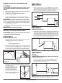
2. Remove the fan’s venturi assembly, which is secured in place with
one screw through the venturi (Figure 1). This is a captive screw and
will stay installed in the venturi. Keep the venturi assembly and the
grill in the carton until needed so they do not get damaged or lost.
3. Choose the location for your fan. To ensure the best air and sound
performance, it is recommended that the length of ducting and
the number of elbows
be kept to a minimum, and that
insulated hard ducting be used.
Larger duct sizes will reduce
noise and airflow restrictions.
4. Select the most convenient electrical
knockout and remove using a straight-
blade screw driver (Figure 2).
5
/
8
"
3
/
8
"
1
/
2
"
1
/
4
"
Figure 1
Figure 2
Figure 3
SECTION 2
New Construction
1. Using the gauge on the fan’s housing (Figure 3), line up housing
so that it will be flush with the finished ceiling or wall. Position
the fan so that the tabs rest flat against the joist or stud and secure
with four nails (not provided) to ensure proper installation.
SECTION 3
Existing Construction
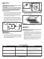
1. Position housing against the joist or stud and trace an outline of the
housing onto the ceiling/wall material (Figure 4). Set housing aside
and cut opening, being careful not to cut or damage any electrical
or other hidden utilities. Place housing next to the joist or stud and
insure that it is flush with the finished ceiling. Secure with four nails
(not provided) to ensure proper installation (Figure 3).
SECTION 4
Ducting
CAUTION: ALL DUCTING MUST COMPLY WITH LOCAL AND
NATIONAL BUILDING CODES.
1. Connect the ducting to the fan’s duct collar (Figure 5). Secure in
place using tape or screw clamp. Always duct the fan to the
outside through a wall or roof cap.
NOTE: If damper detaches from unit, reattach by snapping the collar
back onto the unit. It is designed to only fit one way.
Figure 4
Figure 5
2 of 4
www.geelectrical.com

210572116 Rev. B 5-06
SECTION 5
Wiring
CAUTION: MAKE SURE POWER IS SWITCHED OFF AT SERVICE
PANEL BEFORE STARTING INSTALLATION.
CAUTION: ALL ELECTRICAL CONNECTIONS MUST BE MADE
IN ACCORDANCE WITH LOCAL CODES, ORDINANCES, OR NATIONAL
ELECTRICAL CODE. IF YOU ARE UNFAMILIAR WITH METHODS OF
INSTALLING ELECTRICAL WIRING, SECURE THE SERVICES OF A
QUALIFIED ELECTRICIAN.
1. Run wiring from an approved wall switch carrying the appropriate
rating. One neutral (white), one ground (green or bare copper),
and one hot (black lead connected to the switch). Secure the
electrical wires to the housing with an approved electrical
connector. Make sure you leave enough wiring in the box to make
the connection to the fan’s receptacle.
2. From where you have access to inside the fan’s junction box,
connect the White wire from the house to the White wire from
the fan’s receptacle. Connect the Black wire from the wall switch
to the Black wire from the fan’s receptacle. Connect the ground
wire from the house to the Green wire from the fan’s receptacle
(Figure 6). Use approved methods for all connections.
SECTION 6
Completing the Installation
1. Reinstall the fan’s venturi by holding it at approximately a 45 degree
angle, hook the two tabs on the venturi into the slots on the housing
and secure in place by tightening the venturi screw. Rotate the
blower wheel by hand to ensure it spins freely. Now plug the fan
motor into the receptacle (Figure 7).
Figure 6
Ground
Hot (Black)
Supply
from
house
White
Figure 7
2. Install the grill by squeezing the two ends of the springs together
and installing them up into the slots of the fan’s venturi. Push the
grill up into position (Figure 8).
3. Restore power and test your installation.
SECTION 7
Use and Care
CAUTION: MAKE SURE POWER IS SWITCHED OFF AT SERVICE
PANEL BEFORE SERVICING THE UNIT.
1. Cleaning the Grill: Remove grill and use a mild detergent, such
as dishwashing liquid, and dry with a soft cloth. NEVER USE ANY
ABRASIVE PADS OR SCOURING POWDERS. Completely dry grill
before reinstalling. Refer to instructions in Section 6
Finishing the
Installation
, to reinstall grill.
2. Cleaning the Fan Assembly: Unplug the motor cord from receptacle
and loosen the venturi screw to remove the venturi from the unit.
Wipe all parts with a dry cloth or gently vacuum the fan. NEVER
IMMERSE ELECTRICAL PARTS IN WATER. Refer to instructions
in Section 6
Finishing the Installation
, to reinstall venturi.
Figure 8
Troubleshooting Guide
Trouble Probable Cause Suggested Remedy
1. Fan does not operate when the switch is on. 1a. A fuse may be blown or a circuit tripped. 1a. Replace fuse or reset circuit breaker.
1b. Connector plug from motor is not plugged in. 1b. Turn off power to unit. Remove Grill and plug motor into
receptacle in housing. Restore power to unit.
1c. Wiring is not connected properly. 1c. Turn off power to unit. Check that all wires are connected.
2. Fan is operating, but air moves slower than normal. 2. Obstruction in the exhaust ducting. 2. Check for any obstructions in the ducting. The most common
are bird nests in the roof cap or wall cap where the fan
exhausts to the outside.
3. Fan is operating louder than normal. 3a. Motor is loose. 3a. Turn off power to unit. Remove grill and check that all screws
are fully tightened. Restore power to unit.
3b. Fan blade is hitting housing of unit. 3b. Call your dealer for service.
3 of 4
www.geelectrical.com

WARRANTY
WHAT IS COVERED?
Full Five Year Parts Warranty from date of original proof of purchase. We will
provide, free of charge, a replacement part that fails due to manufacturing
defect in material or workmanship, when installed and used as directed in
the User’s Guide.
This warranty is extended to the original purchaser for products purchased
for ordinary home use.
Read your User’s Guide. If you have any questions about operating the product, please contact your dealer.
Some states and provinces do not allow the exclusion or limitation of incidental or consequential damages and some states do not allow limitations on how
long an implied warranty lasts, so these exclusions or limitations may not apply to you. This warranty gives you specific legal rights and you may have other
rights which vary from state to state and province to province.
WHAT IS NOT COVERED?
• Installation services or service trips to your home to teach you how to use
the product.
• Labor costs or the cost of replacement components as part of routine
maintenance.
• Failure or defects in product arising from Improper installation
If you have an installation problem, contact your dealer or installer. You are
responsible for providing adequate electrical, exhausting and other connecting
facilities. See the Installation Instructions provided with this product for
electrical, exhaust and connection details.
• Replacement of house fuses or resetting of circuit breakers.
• Failure of the product if it is used for something other than the intended
purpose of manufacturer or used commercially.
• Damage to the product caused by accident, fire, floods, acts of customer,
or acts of God.
This warranty contains the sole and exclusive warranty of GE for claims based on defects in these products. Upon the expiration of the warranty period, all
such liability shall terminate. There are no other warranties, whether written, oral, implied or statutory. NO IMPLIED STATUTORY WARRANTY OF MERCHANTABILITY
OR FITNESS FOR PARTICULAR PURPOSE SHALL APPLY.
IN NO EVENT SHALL GE BE LIABLE FOR ANY SPECIAL, CONSEQUENTIAL, INDIRECT, OR INCIDENTAL DAMAGES, SUCH AS, BUT NOT LIMITED TO, LOSS OF PROFIT
OR REVENUES, LOSS OF USE OF THE PRODUCTS OR ANY ASSOCIATED EQUIPMENT, DAMAGE TO ASSOCIATED EQUIPMENT, OR COST OF SUBSTITUTE PRODUCTS.
IN NO EVENT, SHALL GE’S LIABILITY TO BUYER FROM THE SALE OF THESE PRODUCTS EXCEED THE PRICE OF THE DEFECTIVE PRODUCT SOLD AND ANY SUCH
LIABILITY SHALL TERMINATE UPON THE EXPIRATION OF THE WARRANTY PERIOD.
210572116 Rev. B 5-06
# Qty. Description Replacement Part #
1 1 Fan Housing 5S1201001
2 1 3" Plastic Collar 5S1201002
3 1 3" Plastic Damper 5S1201003
4 1 Polarized Receptacle 5S1999001
5 1 #10 Ground Screw 5S1999002
6 1 14 ga Ground Wire 5S1999003
7 1 Goose Neck Wire Cover 5S1201004
8 1 #8 Screw 5S1999004
9 1 Motor Plate 5S1201005
10 1 Captive Screw 5S1999005
11 1 Motor 5S2201001
12 2 Hex Nut 5S1999006
13 1 Impeller 5S1299001
14 1 Scroll 5S1201006
15 2 Grill Springs 5S1201007
16 1 Grill 5S1201008
1
14
2
3
4
5
6
7
8
9
10
11
12
13
15
16
4 of 4
www.geelectrical.com
-
 1
1
-
 2
2
-
 3
3
-
 4
4


Ask a question and I''ll find the answer in the document
Finding information in a document is now easier with AI
Related papers
Other documents
-
AirKing AK100L Installation guide
-
Air King BFQ110 Installation guide
-
-
Air King ASF70 User manual
-
Air King AS50 User manual
-
-
-
Air King ASF70 Installation guide
-
Air King FRAS60 Installation guide
-