
OPERATOR'S MANUAL

THANK YOU
Thank you for buying this quality product. This modern
outdoor power tool will provide many hours of useful
service. You will find it to be a great labor-saving device.
This operator's manual provides you with easy-to-under-
stand operating instructions. Read the whole manual
and follow all the instructions to keep your new outdoor
power tool in top operating condition. The other manual
that came with your power tool, the parts manual,
contains all the information that you need to order parts.
PRODUCT REFERENCES, ILLUSTRATIONS AND
SPECIFICATIONS
All information, illustrations and specifications in this
manual are based on the latest product information
available at the time of printing. We reserve the right to
make changes at any time without notice.
Copyright @1998 Ryobi Outdoor Products, Inc.
All Rights Reserved.
Click-Link ® is a registered trademark of Ryobi Outdoor
Products.
Bump Head TM is a trademark of Ryobi Outdoor
Products.
SERVICE INFORMATION
Service on this unit both within and after the warranty
:}eriod should be performed only by an authorized and
approved service dealer.
Dial:
1-800-345-8746 in the United States or
1-800-265-6778 in Canada
to obtain the listing of the authorized service dealer
nearest you.
DO NOT RETURN THE UNIT TO THE RETAILER.
NOTE:PROOF OF PURCHASE WILL BE REQUIRED
FOR WARRANTY SERVICE.
Make sure this manual is carefully read and understood
before starting or operating this equipment.
THIS PRODUCT IS COVERED BY ONE OR MORE OF
THE US PATENTS LISTED BELOW: 5,076,149;
4,901,682; 4,779,405; 4,651,422; 4,505,040; 4,463,498;
4,369,742; 4,342,236; 4,223,441; 2,125,688; D-249,012;
D-239,329;
OTHER PATENTS PENDING.
I.
II.
California Emission Regulations ................. 3
Rules for Safe Operation ..................... 4-8
A. Important Safty Information ................ 4-5
B. Safety and International Symbols ........... 6-7
C. Know Your Unit ........................... 8
III. Oil and Fuel Information ....................... 9
IV. Starting/Stopping Instructions ................. 10
V.
Operating Instructions .................... 11-13
A. Operating the Click-Link System ............. 11
B. Holding the Trimmer ...................... 12
C. Adjusting the D Handle .................... 12
D. Adjusting Trimming Line Length ............. 12
E. Tips for Best Trimming Results .............. 13
F. Decoritive Trimming ....................... 13
VI.
Maintenance and Repair Instructions ......... 13-18
A. Maintenance Schedule .................... 13
B. Line Installation ....................... 14-15
C. Installing a Prewound Reel ................. 15
D. Air Filter Maintenance ..................... 16
E. Carburetor Adjustment .................... 17
F. Replacing the Spark Plug .................. 18
G. Accessories/Replacement parts ............. 18
VII. Cleaning and Storage ........................ 19
VIII.Troubleshooting Chart ....................... 20
IX. Specifications .............................. 21
X. Warranty ............................... 23-24
CONTENTS OF CARTON
This carton should include the following:
• Model 2079rTrimmer
• Operator's Manual
• Parts Manual
• Product Registration Card
• Bottle of 2-Cycle Oil

Thisunitmeetsthe1995to1998Californiaemissionsregulationsforsmalloff-roadengines.Theseunitsareidentifiedby
thelabelontheengineofyourproduct.Atypicalidentificationlabelisshown.
Toensurethatyourunitcontinuestomeettheseregulations,refertothefollowinginformationandinstructionsinthis
operator'smanual.
MAINTENANCESPECIRCA_ON
ANDADJUSmEhTS.j
California Proposition 65 Warning:
THE ENGINE EXHAUST FROM THIS
PRODUCT CONTAINS CHEMICALS
KNOWN TO THE STATE OF CALIFORNIA
TO CAUSE CANCER, BIRTH DEFECTS
OR OTHER
REPRODUCTIVE HARM,
NOTE: For users on U.S. Forest Land and in the states of California, Maine, Oregon and Washington. All U.S. Forest
Land and the state of California (Public Resources Codes 4442 and 4443), Oregon and Washington require, by law that
certain internal combustion engines operated on forest brush and/or grass-covered areas be equipped with a spark
arrestor, maintained in effective working order, or the engine be constructed, equipped and maintained for the prevention
of fire. Check with your state or local authorities for regulations pertaining to these requirements. Failure to follow these
requirements could subject you to liability or a fine. This unit is factory equipped with a spark arrestor. If it requires
replacement, ask your LOCAL SERVICE dealer to install the Accessory Part #181696 Spark Arrestor Kit.
FOR QUESTIONS, CALL 1-800-345-8746 IN U.S.OR 1-800:265-6778 inCANADA
Read the Operator's Manual(s) and follow all warnings and safety instructions. Failure to do so can
result in serious injury to the operator and/or bystanders.

The purpose of safety symbols is to attract your atten-
tion to possible dangers. The safety symbols, and their
explanations, deserve your careful attention and
understanding. The safety warnings do not by them-
selves eliminate any danger. The instructions or
warnings they give are not substitutes for proper acci-
dent prevention measures.
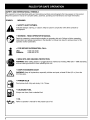
SYMBOL MEANING
SAFETY ALERT SYMBOL: Indicates dan-
ger, warning, or caution. Attention is required
in order to avoid serious personal injury. May
be used in conjunction with other symbols or
pictographs.
NOTE: Advises you of information or instructions vital to
the operation or maintenance of the equipment.
DANGER: Failure to obey a safety warning
will result in serious injury to yourself or to
others. Always follow the safety precautions
to reduce the risk of fire, electric shock, and
personal injury.
_ ARNING: Failure to obey a safety warning
can result in injury to yourself and others.
Always follow the safety precautions to
reduce the risk of fire, electric shock, and
personal injury.
_L AUTION: Failure to obey a safety warning
may result in property damage or personal
injury to yourself or to others. Always follow
the safety precautions to reduce the risk of
fire, electric shock, and personal injury.
• IMPORTANT SAFETY INFORMATION •
READ ALL INSTRUCTIONS BEFORE
OPERATING
• Read the instructions carefully. Be familiar with the
controls and proper use of the unit.
• Do not operate this unit when tired, ill, or under the
influence of alcohol, drugs, or medication.
• Children and teens under the age of 15 must not use
the unit, except for teens guided by an adult.
• Inspect the unit before use. Replace damaged parts.
Check for fuel leaks. Make sure all fasteners are in
place and secure. Replace cutting attachment parts
that are cracked, chipped, or damaged in any way.
Make sure the cutting attachment is properly
installed and securely fastened. Be sure the cutting
attachment shield is properly attached, and
positioned as recommended. Failure to so can result
in personal injury to the operator and bystanders, as
well as damage to the unit
• Use only 0.095 inch (2.41 mm) diameter genuine
Ryobi replacement line. Never use metal-reinforced
line, wire, or rope, etc.. These can break off and
become a dangerous projectile.
• Be aware of the risk of injury to the head, hands and
feet.
• Clear the area to be cut before each use. Remove all
objects such as rocks, broken glass, nails, wire, or
string which can be thrown or become entangled in
the cutting attachment. Clear the area of children,
bystanders, and pets. At a minimum, keep all
children, bystanders and pets outside a 50 ft. (15 m.)
radius; there still may be a risk to bystanders from
thrown objects. Bystanders should be encouraged to
wear eye protection. If you are approached, stop the
engine and cutting attachment immediately.
• Squeeze the throttle control and check that it returns
automatically to the neutral position. Make all
adjustments or repairs before using unit.
SAFETY WARNINGS FOR GAS TRIMMERS
_ ARNING: Gasoline is highly flammable,
and its vapors can explode if ignited. Take
the following precautions:
• Store fuel only in containers specifically designed
and approved for the storage of such materials.
• Avoid creating a source of ignition for spilled fuel. Do
not start the engine until fuel vapors dissipate.
Always stop the engine and allow it to cool before
filling the fuel tank. Never remove the cap of the fuel
tank, or add fuel, when the engine is hot. Never
operate the unit without the fuel cap securely in
place. Loosen the fuel tank cap slowly to relieve any
pressure in the tank.
Mix and add fuel in a clean, well-ventilated area
outdoors where there are no sparks or flames.
Slowly remove the fuel cap only after stopping
engine. Do not smoke while fueling or mixing fuel.
Wipe up any spilled fuel from the unit immediately.
Move the unit at least 30 ft. (9.1 m) from the fueling
source and site before starting the engine. Do not
smoke, keep sparks and open flames from the area
while adding fuel or operating the unit.
WHILE OPERATING
• Never start or run the unit inside a closed room or
building. Breathing exhaust fumes can kill. Operate
this unit only in a well ventilated area outdoors.
Wear safety glasses or goggles that are marked as
meeting ANSI Z87.1-1989 standards, and
ear/hearing protection when operating this unit.
Wear a face or dust mask if the operation is dusty.
Long sleeve shirts are recommended.
The cutting attachment shield must always be in
place while operating the unit as a trimmer. Do not
operate unit without both trimming lines extended,
and the proper line installed. Do not extend the
trimming line beyond the length of the shield.

Thecuttingattachmentmaybespinningduring
carburetoradjustments.Wearyourprotective
equipmentandobserveallsafetyinstructions.For
unitsequippedwithaclutch,besurethecutting
attachmentstopsturningwhentheengineidles.
Whentheunitisturnedoffmakesurethecutting
attachmenthasstoppedbeforetheunitissetdown.
AdjusttheDhandleto providethebestgrip.
Besurethecuttingattachmentisnotincontactwith
anythingbeforestartingtheunit.
Usetheunitonlyindaylightorgoodartificiallight.
Avoidaccidentalstarting.Beinthestartingposition
wheneverpullingthestarterrope.Theoperatorand
unitmustbeinastablepositionwhilestarting.See
Starting/StoppingInstructions.
Usetherighttool.Onlyusethistoolforthepurpose
intended.
Donotoverreach.Alwayskeepproperfootingand
balance.
Alwaysholdtheunitwithbothhandswhen
operating.Keepafirmgriponboththefrontandrear
handleorgrips.
Keephands,face,andfeetatadistancefromall
movingparts.Donottouchortrytostopthecutting
attachmentwhenitisrotating.
Donottouchtheengineormuffler.Thesepartsget
extremelyhotfromoperation.Whenturnedoffthey
remainhotforashorttime.
Donotoperatetheenginefasterthanthespeed
neededtocut,trimoredge.Donotruntheengineat
highspeedwhennotcutting.
Alwaysstoptheenginewhencuttingisdelayedor
whenwalkingfromonecuttinglocationtoanother.
Ifyoustrikeorbecomeentangledwithaforeign
object,stoptheengineimmediatelyandcheckfor
damage.Donotoperatebeforerepairingdamage.
Donotoperatetheunitwithlooseordamagedparts.
Stopandswitchtheenginetooffformaintenance,
repair,orforchangingthecuttingattachmentor
otherattachments.
UseonlygenuineRyobireplacementpartswhen
servicingthisunit.Thesepartsareavailablefrom
yourauthorizedservicedealer.Donotuseparts,
accessoriesorattachmentsnotauthorizedbyRyobi
forthisunit.Doingsocouldleadtoseriousinjuryto
theuser,ordamagetotheunit,andvoidyour
warranty.
Keepunitcleanofvegetationandothermaterials.
Theymaybecomelodgedbetweenthecutting
attachmentandshield.
Toreducefirehazard,replacefaultymufflerand
sparkarrestor,keeptheengineandmufflerfreefrom
grass,leaves,excessivegreaseorcarbonbuildup.
Wearheavy,longpants,bootsandgloves.Donot
wearlooseclothing,jewelry,shortpants,sandalsor
gobarefoot.Securehairaboveshoulderlevel.
OTHER SAFETY WARNINGS
• Never store the unit, with fuel in the tank, inside a
building where fumes may reach an open flame or
spark.
• Allow the engine to cool before storing or
transporting. Be sure to secure the unit while
transporting.
• Store the unit in a locked up and dry, or high and dry
place to prevent unauthorized use or damage. Keep
out of the reach of children.
Never douse or squirt the unit with water or any
other liquid. Keep handles dry, clean and free from
debris. Clean after each use, see Cleaning and
Storage instructions.
• Keep these instructions. Refer to them often and use
them to instruct other users. If you loan someone
this unit, also loan them these instructions.
WARNING" To avoid serious personal injury
do not install a blade on this unit as
configured. Brushcutter Kit # 300026 is
available to convert this model into a
trimmer / brushcutter.
SAVE THESE INSTRUCTION

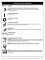
SAFETY AND INTERNATIONAL SYMBOLS
This operator's manual describes safety and international symbols and pictographs that may appear on this product.
Read the operator's manual for complete safety, assembly, operating and maintenance and repair information.
SYMBOL MEANING
" SAFETY ALERT SYMBOL
Indicates danger, warning, or caution. May be used in conjunction with other symbols or
pictographs.
• WARNING - READ OPERATOR'S MANUAL
Read the operator's manual before starting or operating this unit. Failure to follow operating
instructions and safety precautions in the operator's manual can result in serious injury to the
operator and/or bystanders.
• FOR SERVICE INFORMATION, CALL:
USA: 1-800-345-8746
CANADA: 1-800-265-6778
@
• WEAR EYE AND HEARING PROTECTION
WARNING: Wear safety glasses or goggles that are marked as meeting ANSI Z87.1-1989 standards
and ear/hearing protection when operating this unit.
• KEEP BYSTANDERS AWAY
WARNING: Keep all bystanders, especially children and pets, at least 50 feet (15 m.) from the
trimming area.
5-7x
• PRIMER BULB
Push primer bulb, fully and slowly, 5 to 7 times.
• UNLEADED FUEL
Always use clean, fresh unleaded fuel.
• OIL
Refer to operator's manual for the proper type of oil.

SYMBOL MEANING
_._ • THROWN OBJECTS AND ROTATING CUTTER CAN CAUSE SEVERE INJURY
WARNING: Do not operate without the cutting attachment shield in place. Keep away from the
rotating cutting attachment.
I
O
m
• ON/OFF STOP CONTROL
ON / START / RUN
• ON/OFF STOP CONTROL
OFF OR STOP
• HOT SURFACE WARNING
Do not touch a hot muffler or cylinder. You may get burned. These parts get extremely hot from
operation. When turned off they remain hot for a short time.
• SHARP BLADE
WARNING: Sharp blade on string guard. To prevent serious injury, do not touch line cutting blade.
• CHOKE CONTROL
A. START position.
B. RUN position.
• TRIMMER/BRUSHCUTTER SAFETY
WARNING: Thrown objects and rotating cutter can cause severe injury. Keep bystanders, especially
children and pets, at least 50 feet (15 m.) away from the cutting area. The cutting attachment shield
must be used when using the trimmer cutting attachment.
WARNING: To avoid serious personal injury do not install a blade on this unit as configured.
Brushcutter Kit # 300026 is available to convert this model into a trimmer / brushcutter.
WARNING: The operation of any power tool can cause foreign objects to be thrown into your eyes.
This can lead to severe eye damage. Before commencing power tool operation, always wear safety
glasses or goggles that are marked as meeting ANSI Z87.1-1989 standards, and a full face shield
when needed.

APPLICATIONS
As a trimmer;
• Cutting grass and light weeds.
• Edging
• Decorative trimming around trees, fences,
etc.
With optional brushcutter kit;
• Cutting weeds and light bush of up to 1/2
inch in diameter.
Other optional accessories may be used with
the 2079r. See list of add-ons on page 11.
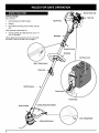
Grip
Gas Cap
Throttle Control
D-Handle
Air Filter Cover
Start / Stop Control
Shaft Housing_
Choke Lever
Primer Bulb
Gear Housing
\
\
\
\
\
Cutting Attachment Shield
Attachment
Blade

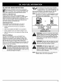
OIL AND FUEL MIXING INSTRUCTIONS
OId and/or improperly mixed fuel is usually the
main reasons for the unit not running properly. Be
sure to use fresh, clean unleaded fuel. Follow the
instructions carefully for the proper fuel/oil mixture.
Definition of Blended Fuels
Today's fuels are often a blend of gasoline and
oxygenates such as ethanol, methanol or MTBE (ether).
Alcohol-blended fuel absorbs water. As little as 1%
water in the fuel can make fuel and oil separate. It forms
acids when stored. When using alcohol-blended fuel,
use fresh fuel (less than 60 days old).
Using Blended Fuels
If you choose to use a blended fuel, or its use is
unavoidable, follow recommended precautions.
• Always use fresh fuel mix per your operator's
manual.
• Use the fuel additive STA-BIL ® or an equivalent.
• Always agitate the fuel mix before fueling the unit.
• Drain the tank and run the engine dry before storing
the unit.
Using Fuel Additives
The use of fuel additives, such as STA-BIL ® Gas
Stabilizer or an equivalent, will inhibit corrosion and
minimize the formation of gum deposits. Using a fuel
additive can keep fuel from forming harmful deposits in
the carburetor for up to six (6) months. Add 0.8 oz.
(23 ml.) of fuel additive per gallon of fuel according to the
instructions on the container. NEVER add fuel additives
directly to the unit's fuel tank.
CAUTION: For proper engine operation and
maximum reliability, pay strict attention to the
oil and fuel mixing instructions on the 2-cycle
oil container. Using improperly mixed fuel can
severe y damage the eng ne.
_ Thoroughly mix the proper ratio of RYOBI
2-cycle engine oil with unleaded gasoline in a
separate fuel can. Use a 32:1 fuel/oil ratio. Do
not mix them directly in the engine fuel tank. See the
table below for specific gas and oil mixing ratios.
NOTE: One gallon (3.8 liters) of unleaded gasoline mixed
with one 4 oz. (120 ml.) bottle of RYOBI 2 Cycle
OIL makes a 32:1 fuel/oil ratio.
UNLEADED GAS RYOBI 2 CYCLE OIL
1 US. GALLON + 4.0 FL OZ.
(3.8 LITERS) (120 ml)
1 LITER + 30 ml
MIXING RATIO - 32:1
WARNING: Gasoline is extremely flammable.
Ignited Vapors may explode. Always stop the
engine and allow it to cool before filling the
fuel tank. Do not smoke while filling the tank.
Keep sparks and open flames at a distance
from the area.
[,_ ARNING: Remove fuel cap slowly to avoid
injury from fuel spray. Never operate the unit
without the fuel cap securely in place.
_i ARNING: Add fuel in a clean, well
ventilated area outdoors. Wipe up any spilled
fuel immediately. Avoid creating a source of
ignition for spilt fuel. Do not start the engine
until fuel vapors dissipate.
NOTE: Dispose of the old fuel/oil mix in accordance to
Federal, State, and Local regulations.

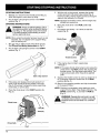
STOPPING INSTRUCTIONS
1. Release your hand from the throttle control (Fig. 3).
Allow the engine to cool down by idling.
2. Put the Start / Stop Engine Control in the STOP
position (Fig. 1).
STARTING INSTRUCTIONS
WARNING: Avoid accidental starting. Be in
the starting position when pulling the starter
rope (Fig. 3). The operator and unit must be
in a stable position while starting to avoid
serious personal injury.
NOTE."When using the shoulder harness, have it on and
adjusted, but not clipped to the support fitting
prior to starting unit.
1. Mix gas with oil. Fill fuel tank with fuel/oil mixture.
See Oil and Fuel Mixing Instructions on Pg. 9.
2. Put the Start / Stop Engine Control in the START
position (Fig. 1).
5. With the unit on the ground, squeeze the throttle
control and hold. Pull starter rope briskly (Fig. 3).
Continue pulling until the engine sounds as though it
wants to run (normally 2 to 5 pulls).
NOTE." Squeeze the throttle control until the engine has
started and warmed up.
6. Place the choke lever in the RUN position (B)
(Fig. 2).
7. Pull starter rope briskly 1 to 3 times to start the
engine (Fig. 3).
Starter Rope
.
4.
bControl
Fig. 1
Fully press and release primer bulb slowly 5 to 7
times. Fuel should be felt and visible in the bulb
(Fig. 2). If fuel hasn't entered the bulb, press three
more times, or until it does.
Place the choke lever in the START position (A)
(Fig. 2).
Choke Lever
Throttle Control
Fig. 3
8. If the engine does not start, repeat steps
4 through 7.
NOTE." If the engine floods while trying to start, place the
choke lever in the RUN position (B). Squeeze the
throttle control. Pull the starter rope briskly. The
engine should start within three (3) to eight (8)
pulls.
9. Squeeze the throttle control to warm up engine for 5
to 10 seconds. Place the choke lever in the RUN
position (B) (Fig. 2).
10. Stand in the operating position and clip the shoulder
to the support fitting
NOTE." Choking is unnecessary when starting a warm
engine. Put the Start / Stop Engine Control in the
START position (Fig. 1), and start in RUN (B)
(Fig. 2).
_ WARNING: Operate this unit only in a well
ventilated area outdoors. Carbon monoxide
exhaust fumes can be lethal in a confined
area.
Run (B)
Primer Bulb .F
Fig. 2
10

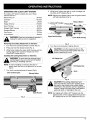
OPERATINGTHECLICK-LINK® SYSTEM
The Click-Link ® system enables the use of these
optional add-ons.
Blower/Vacuum .......................... BV72Or
Cultivator .............................. GC72Or
Edger .................................. LE72Or
Hedge Trimmer .......................... HS72Or
Snow Thrower ........................... ST72Or
Straight Shaft Trimmer .................... SS725r
Sweeper/Blower ......................... SB72Or
Tree Pruner ............................. TP72Or
Turbo Blower ............................ TB72Or
WARNING: Read and understand operator's
manual for add-on prior to operation.
Removing the Cutting Attachment or Add-Ons:
1. Turn the knob counterclockwise to loosen (Fig. 4).
2. Press and hold the release button (Fig. 4).
3. While firmly holding the upper shaft housing, pull the
cutting attachment or add-on straight out of the
Click-Link ® coupler (Fig. 4).
Installing the Cutting Attachment or Add-Ons:
WARNING: To avoid serious personal injury
and damage to the unit, shut unit off before
removing or installing add-ons.
NOTE: To make installing or removing the add-on
easier, place the unit on the ground or on a work
bench.
1. Turn knob counterclockwise to loosen (Fig.4).
Click-Link® Coupler Release Button
\
Guide Recess
Fig. 4
2. While firmly holding the add-on, push it straight into
the Click-Link ® coupler (Fig. 5).
NOTE: Aligning the release button with the guide recess
will help installation (Fig. 5).
Release Button
Click-Link ® Coupler
Upper Shaft Housing
Lower Shaft Housing
Fig. 5
3. Turn the knob clockwise to tighten (Fig. 6).
[,_ AUTION: Lock the release button in the
primary hole and securely tighten the knob
before operating this unit.
90° Edging Hole
180° Edging Hole
Fig. 6
CAUTION: The cutting attachment and
add-ons with the Click-Link ® system are to
be used in the primary hole unless stated
otherwise in the specific add-ons operator's
manual. Using the wrong hole could lead to
personal injury, or damage to the unit.
NOTE: For edging with Click-Link ® models, lock the
release button of the cutting attachment into the
90° edging hole orthe 180° edging hole (Fig. 6).
11

HOLDING THE TRIMMER
WARNING: Always wear eye, hearing, foot
and body protection to reduce the risk of
injury when operating this unit.
Before operating the unit, stand in the operating position
(Fig. 7). Check for the following:
• The operator is wearing eye protection and proper
clothing.
• The right arm is slightly bent, and the hand is holding
the shaft grip.
• The left arm is straight, and the hand is holding the
handle.
• The unit is below waist level.
• The cutting attachment is parallel to the ground and
easily contacts the vegitation to be cut without the
operator having to bend over.
Fig. 7
ADJUSTING THE D HANDLE
If the D handle is not adjusted to provide you with a
comfortable operation position:
1. Loosen the four (4) screws with a Phillips screwdriver
(Fig. 8).
2. Position the D handle forward or backward to the
location that will provide you the best grip.
3. Tighten the screws securely.
D Handle
4 Screws
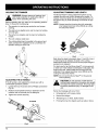
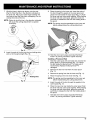
ADJUSTING TRIMMING LINE LENGTH
The Bump Head TM cutting attachment allows you to
release trimming line without stopping the engine. To
release more line, lightly tap the cutting attachment on
the ground (Fig. 9) while operating the trimmer at high
speed.
NOTE: Always keep the trimming line fully extended.
Line release becomes more difficult as cutting
line becomes shorter
Fig. 9
Each time the head is bumped, about 1 inch (25.4 mm.)
of trimming line is released. A blade in the cutting
attachment shield will cut the line to the proper length if
excess line is released.
For best results, tap the Bump Head TM on bare ground
or hard soil. If line release is attempted in tall grass, the
engine may stall. Always keep the trimming line fully
extended. Line release becomes more difficult as the
cutting line becomes shorter.
NOTE." Do not rest the Bump Head TM on the ground
while operating.
_ AUTION: Do not remove or alter the line
cutting blade assembly. Excessive line length
will make the clutch overheat. This may lead
to serious personal injury or damage to the
unit.
Some line breakage will occur from:
• Entanglement with foreign matter
• Normal line fatigue
• Attempting to cut thick, stalky weeds
• Forcing the line into objects such as walls or fence
Fig. 8
12

TIPS FOR BEST TRIMMING RESULTS
• Keep the cutting attachment parallel to the ground.
• Do not force the cutting attachment. Allow the tip of
the line to do the cutting, especially along walls.
Cutting with more than the tip will reduce cutting effi-
ciency and may overload the engine.
• Cut grass over 8 in. (200 mm.) by working from top
to bottom in small increments to avoid premature
line wear or engine drag.
• Cut from left to right whenever possible. Cutting to
the right improves the unit's cutting efficiency.
Clippings are thrown away from the operator.
• Slowly move the trimmer into and out of the cutting
area at the desired height. Move either in a forward-
backward or side-to-side motion. Cutting shorter
lengths produces the best results.
• Trim only when grass and weeds are dry.
• The life of your cutting line is dependent upon;
• Following the previous trimming techniques
• What vegetation is being cut
• Where it's being cut
For example, the line will wear faster when trimming
against a foundation wall as opposed to trimming
around a tree.
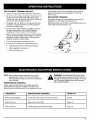
DECORATIVE TRIMMING
Decorative trimming is accomplished by removing all
vegetation around trees, posts, fences, etc.
Rotate the whole unit so that the cutting attachment is at
a 30 ° angle to the ground (Fig. 10).
NOTE: Some maintenance procedures may require
special tools or skills. If you are unsure about
these procedures take your unit to an authorized
service dealer.
MAINTENANCE SCHEDULE
These required maintenance procedures should be
performed at the frequency stated in the table. They
should also be included as part of any seasonal tune-up.
WARNING: To prevent serious injury, never I
do maintenance or repairs with unit running. I
Always do maintenance and repairs on a cool I
unit. Disconnect spark plug wire to ensure
the unit will not start.
FREQUENCY MAINTENANCE REQUIRED REFER TO:
Before Starting Engine Fill fuel tank with correct oil and fuel mixture. Page 9
Every 10 Hours Clean and re-oil air filter. Page 16
Every 50 Hours Check spark plug condition and gap. Page 18
13

LINE INSTALLATION
Always use genuine Ryobi 0.095 inch (2.41 mm.)
replacement line. Larger line may make the engine
overheat or fail.
WARNING: Never use metal-reinforced line,
wire, or rope, etc.. These can break off and
become a dangerous projectile.
There are two methods to replace the trimming line.
• Wind the inner reel with new line
• Install a prewound inner reel
NOTE: Replacement line Part # 612454, or a prewound
reel, Part # 147345 can be purchased from your
local authorized dealer.
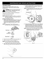
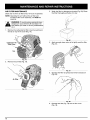
Winding the Existing Inner Reel
1. Hold the outer spool with one hand and unscrew the
Bump Knob TM counterclockwise (Fig. 11). Inspect
the bolt inside the Bump Knob TM to make sure it
moves freely. Replace the Bump Knob TM if dam-
aged.
NOTE: A Bump Knob TM, Part # 180814 can be
purchased from your local authorized dealer.
Outer Spool
Spring _
Inner Reel__
Bump Knob TM _
Fig. 11
2. Remove the inner reel from the outer spool (Fig. 11).
3. Remove spring from the inner reel (Fig. 11).
NOTE: An inner reel spring, Part # 610636 can be
purchased from your local authorized dealer.
4.
Use a clean cloth to clean the the inner reel, spring,
shaft, and inner surface of the outer spool (Fig. 12).
_\\\\\
5. Check the indexing teeth on the innerreel and outer
spool for wear (Fig. 13). If necessary, remove burrs
or replace the reel and spool.
NOTE: A cutting attachment outer spool, Part # 147494
can be purchased from your local authorized
dealer.
\
Fig. 13
6. Take approximately 25 feet (7.6 m) of new 0.095 inch
diameter trimming line, loop it into two equal lengths.
Insert each end of the line through one of the two
holes in the inner reel (Fig. 14). Pull the line through
the inner reel so that the loop is as small as possible.
NOTE: Always use the correct line length when installing
trimming line on the unit. The line may not
release properly if the line is too long.
Fig. 14
Fig. 12
14

7. Wind the lines in tight even layers, onto the reel
(Fig.15). Wind the line in the direction indicated on
the inner reel. Place your index finger between the
two lines to stop the lines from overlapping. Do not
overlap the ends of the line.
NOTE: Failure to wind the line in the direction indicated
will cause the cutting attachment to operate
incorrectly.
\
\
\
\
\
\
\
\
\ \
\\ \
\
\
\
\
\
\
\
\
Fig. 15
8. Insert the ends of the line into the two holding slots
and cut to the same length (Fig. 16).
Slots
Fig. 16
9. Place the spring in the inner reel. Insert the ends of
the line through the eyelets in the outer spool and
place inner reel inside the outer spool (Fig. 17). Push
the inner reel and outer spool together. While holding
the inner reel and outer spool, grasp the ends and
pull firmly to release the line from the holding slots in
the spool.
NOTE: The spring must be assembled on the inner reel
before reassembling the cutting attachment.
Fig. 17
10. Hold the inner reel in place and install the Bump
Knob TM by turning clockwise. Tighten securely.
Installing a Prewound Reel
1. Hold the outer spool with one hand and unscrew the
Bump Knob TM counterclockwise (Fig. 11). Inspect
the bolt inside the Bump Knob TM to make sure it
moves freely. Replace the Bump Knob TM if
damaged.
2. Remove the old inner reel from the outer spool
(Fig. 11)
3. Remove the spring from the old inner reel (Fig. 11).
4. Place the spring in the new inner reel (Fig. 11).
NOTE: The spring must be assembled on the inner reel
before reassembling the cutting attachment.
5. insert the ends of the line through the eyelets in the
outer spool (Fig. 17).
.
Place the new inner reel inside the outer spool. Push
the inner reel and outer spool together. While holding
the inner reel and outer spool, grasp the ends and
pull firmly to release the line from the holding slots in
the spool.
7. Hold the inner reel in place and install the Bump
Knob TM by turning clockwise. Tighten securely.
15

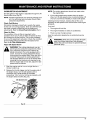
AIR FILTER MAINTENANCE
Clean and re-oil the air filter every 10 hours of operation.
NOTE: Operating the unit without the air filter and
air filter/muffler cover assembly, will VOID the
warranty.
WARNING: To avoid serious personal injury,
always turn your trimmer off and allow it to
cool before you clean or do any maintenance
on it.
1. Remove the carburetor/air filter cover by pushing on
the tab on top of the cover (Fig. 18).
3. Wash the filter in detergent and water (Fig. 20). Rinse
the filter thoroughly and allow it to dry.
J
Carburetor/Air
Filter Cover
Fig. 20
4. Apply enough clean motor oil to lightly coat the filter
(Fig. 21).
Fig. 18
2. Remove the air filter (Fig. 19).
Fig. 21
5. Squeeze the filter to spread and remove excess oil
(Fig. 22).
Air Fil
Fig. 19
Fig. 22
6. Reinstall the filter (Fig. 19) and air filter cover
(Fig. 18).
16

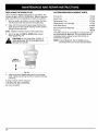
CARBURETOR ADJUSTMENT
The idle speed of the engine is adjustable though the Air
filter/muffler cover (Fig 23).
NOTE: Careless adjustments can seriously damage your
unit. An authorized service dealer should make
carburetor adjustments.
Check Fuel Mixture
Old and/or improperly mixed fuel is usually the reason
for the unit not running properly. Drain and refill the tank
with fresh, properly mixed fuel prior to making any
adjustments. Refer to Oil and Fuel Information, Pg. 9.
Clean Air Filter
The condition of the air filter is important to the
operation of the unit. A dirty air filter will restrict air flow
and change the air/fuel mixture. This is often mistaken
for an out of adjustment carburetor. Check the condition
of the air filter before adjusting the idle speed screw.
Refer to Air Filter Maintenance.
Adjust Idle Speed Screw
WARNING: The cutting attachment may be
spinning during carburetor adjustments. Wear
your protective equipment and observe all
safety instructions. For units equipped with a
clutch, be sure the cutting attachment stops
turning when the engine idles. When the unit is
turned off make sure the cutting attachment
has stopped before the unit is set downlf after
checking the fuel mixture and cleaning the air
filter the engine still will not idle, adjust the idle
speed screw as follows.
1. Start the engine and let it run at a high idle for a
minute to warm up.
2.
Release the throttle trigger and let the engine idle. if
the engine stops, turn the idle speed screw in
clockwise with a small phillips or flat blade
screwdriver 1/8 of a turn at a time (as needed), until
the engine idles smoothly (Fig. 23).
Idle Speed Screw
NOTE: The cutting attachment should not rotate when
the engine idles.
3. if the cutting attachment rotates when the engine
idles, turn the idle speed screw counterclockwise 1/8
of a turn at a time (as needed), to reduce idle speed.
Checking the fuel mixture, cleaning the air filter, and
adjusting the idle speed screw should solve most engine
problems.
If not and:
• The engine will not idle,
• The engine hesitates or stalls on acceleration,
• There is a loss of engine power,
have the carburetor adjusted by an authorized service
dealer.
[,_ ARNING: When the unit is turned off make
sure the cutting attachment has stopped
before the unit is set down to prevent serious
personal injury.
Fig. 23
17

REPLACING THE SPARK PLUG
Use a Champion RCJ6Y spark plug (or equivalent). The
correct air gap is 0.025 in. (0.655 mm.). Remove the plug
after every 50 hours of operation to check its condition.
1. Stop the engine and allow it to cool. Grasp the plug
wire firmly and pull the cap from the spark plug.
2. Clean dirt from around the spark plug. Remove the
spark plug from the cylinder head by turning a 5/8 in.
socket counterclockwise.
Note: Replace cracked, fouled or dirty spark plug.
3. Set the air gap at 0.025 in. (0.555 mm.) using a
feeler gauge (Fig. 24).
CAUTION: Do not sand blast, scrape, or
clean electrodes. Grit in the engine could
damage the cylinder.
l
0.025 in.
(0.655 mm.)
ACCESSORIES/REPLACEMENT PARTS
2-Cycle OIl ............................. 147543
Spark Plug ............................. 181765
Replacement Line ....................... 612454
Replacement Line Cartridge ............... 147345
Inner Reel Spring ........................ 610636
Bump Head Knob Assembly ............... 180814
Fuel Cap ............................... 180000
The 2079r trimmer is convertible to a brushcutter with
the optional Brush Blade Kit. The kit contains all the
necessary parts to safely convert the trimmer to
brushcutter capability.
NOTE= A Brush Blade Kit, Part # 300026 can be
purchased from your local authorized dealer.
A
Fig.24
4. Install a correctly gaped spark plug in the cylinder
head. Tighten by turning the 5/8 in. socket clockwise
until snug.
If using a torque wrench torque to;
110-120 in.-Ib. (12.3-13.5 Nom).
Do not over tighten.
18

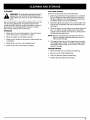
CLEANING
WARNING:To avoid serious personal injury,
always turn your trimmer off and allow it to
cool before you clean or do any maintenance
on it.
Use a small brush to clean off the outside of the unit. Do
not use strong detergents. Household cleaners that
contain aromatic oils such as pine and lemon, and such
as kerosene, can damage plastic housing or handle.
Wipe off any moisture with a soft cloth.
STORAGE
• Never store the unit with gasoline in the tank where
fumes may reach an open flame or spark.
• Allow the engine to cool before storing.
• Store the unit locked up to prevent unauthorized use
or damage.
• Store the unit in a dry, well ventilated area.
• Store the unit out of the reach of children.
LONG TERM STORAGE
If the unit will be stored for an extended time,
1. Drain all gasoline from the gas tank into a container.
Do not use gas that has been stored for more than
60 days. Dispose of the old gasoline in accordance
to Federal, State, and Local regulations.
2. Start the engine and allow it to run until it stalls. This
ensures that all gasoline has been drained from the
carburetor.
.
Allow the engine to cool. Remove the spark plug and
put 1 oz. (30 ml.) of high quality motor oil into the
cylinder. Pull the starter rope slowly to distribute the
oil. Reinstall the spark plug.
NOTE: Remove the spark plug and drain all of the oil
from the cylinder before attempting to start the
trimmer after storage.
4. Thoroughly clean the unit and inspect for any loose
or damaged parts. Repair or replace damaged parts
and tighten loose screws, nuts or bolts. The unit is
ready for storage.
TRANSPORTING
• Allow the engine to cool before transporting.
• Secure the unit while transporting.
• Drain the gas tank before transporting.
• Tighten gas cap before transporting.
19

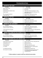
bil-"• : • • e]
CAUSE
Ignition switch is OFF
Empty gas tank
Primer bulb wasn't pressed enough
Engine flooded
Old or improperly mixed fuel
Fouled spark plug
CAUSE
Air Filter is Plugged
Old or improperly mixed fuel
Improper carburetor adjustment
CAUSE
Old or improperly mixed fuel
Improper carburetor adjustment
Cutting head bound with grass
Dirty air filter
CAUSE
Old or improperly mixed fuel
Improper carburetor adjustment
CAUSE
Cutting head bound with grass
Cutting head out of line
Inner reel bound up
Cutting head dirty
Line welded
Linetwisted when refilled
Not enough line is exposed
ACTION
Turn switch to ON
Fill fuel tank
Press primer bulb fully and slowly 5-7 times
Use starting procedure with choke lever in the
RUN position, Pg. 10
Drain fuel tank / Add fresh fuel mixture
Replace or clean the spark plug
ACTION
Replace or clean the air filter
Drain gas tank / Add fresh fuel mixture
Adjust per instruction Pg. 17
ACTION
Drain gas tank / Add fresh fuel mixture
Take to an authorized service dealer for
carburetor adjustment
Stop the engine and clean the cutting attachment
Clean or replace the air filter
ACTION
Drain gas tank / Add fresh fuel mixture
Take to an authorized service dealer for
carburetor adjustment
ACTION
Stop the engine and clean cutting attachment
Refill with new line
Replace the inner reel
Clean inner reel and outer spool
Disassemble, remove the welded section
and rewind the line
Disassemble and rewind the line
Push the Bump Knob and pull out line until
4 in. (102 mm.) of line is outside of the
cutting attachment
If further assistance is required, contact your authorized service dealer.
20
Page is loading ...
Page is loading ...
Page is loading ...
Page is loading ...
-
 1
1
-
 2
2
-
 3
3
-
 4
4
-
 5
5
-
 6
6
-
 7
7
-
 8
8
-
 9
9
-
 10
10
-
 11
11
-
 12
12
-
 13
13
-
 14
14
-
 15
15
-
 16
16
-
 17
17
-
 18
18
-
 19
19
-
 20
20
-
 21
21
-
 22
22
-
 23
23
-
 24
24


Ask a question and I''ll find the answer in the document
Finding information in a document is now easier with AI