Citronic SP200 is a professional power amplifier offering top power, superior performance, and full professional operating features in a roadworthy compact chassis. With its 100W stereo power into 4Ω or 70W into 8Ω, it's perfect for demanding sound reinforcement installations and touring applications. The SP200 features full operating features like detent volume controls, balanced inputs, Speakon outputs, and a built-in limiter for added protection.
Citronic SP200 is a professional power amplifier offering top power, superior performance, and full professional operating features in a roadworthy compact chassis. With its 100W stereo power into 4Ω or 70W into 8Ω, it's perfect for demanding sound reinforcement installations and touring applications. The SP200 features full operating features like detent volume controls, balanced inputs, Speakon outputs, and a built-in limiter for added protection.


-
 1
1
-
 2
2
-
 3
3
-
 4
4
-
 5
5
-
 6
6
-
 7
7
-
 8
8


Citronic SP200 is a professional power amplifier offering top power, superior performance, and full professional operating features in a roadworthy compact chassis. With its 100W stereo power into 4Ω or 70W into 8Ω, it's perfect for demanding sound reinforcement installations and touring applications. The SP200 features full operating features like detent volume controls, balanced inputs, Speakon outputs, and a built-in limiter for added protection.
Ask a question and I''ll find the answer in the document
Finding information in a document is now easier with AI
Related papers
Other documents
-
AMC A Series User manual
-
-
-
-
-
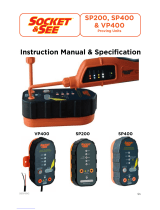 Socket & See VP400 Instruction Manual & Specification
-
Nady Systems SPA 850 User manual
-
-
-
