Dostmann 5005-0200 User manual

Category
Measuring & layout tools
Type
User manual
32
Fig. B
2
3
4
5
6
Fig. A
1
3
4
5
8
7
6
9
1
Fig. C
LOG220_16099908_2016-09-27T103123.PDF LOG220 SN 16099908 V 04.00
Test FW 4.00 Beta
20.10.2016
TEST LOG220
Konfiguration/Configuration
Benutzer/Operator WD
Intervall/Interval 00:00:30
Start möglich durch/Start possible by Taste/Button
Startverzögerung/Start delay 00:00:00
Stopp möglich durch/Stop possible by USB Verbindung/USB connect
Alarmverzögerung/Alarm delay 00:00:00
Alarm unten/Alarm low Alarm oben/Alarm high
Temperatur/Temperature 20.0 °C 30.0 °C
Feuchtigkeit/Humidity 4.0 %rH 70.0 %rH
Rel. Luftdruck/Rel. air pressure 990.0 hPa 1030.0 hPa
Zusammenfassung/Summary
Startzeit/Start time 27.09.2016 10:31:27 Start durch/Start by Taste/Button
Stoppzeit/Stop time 27.09.2016 12:43:27 Stopp durch/Stop by USB Verbindung/USB connect
Datensätze/Records 265 Dauer/Duration 02:12:00
Min Avg Max Höhe ü.NN/Altitude ASL
Taupunkt/Dew point 13.9 °C 14.1 °C 16.2 °C
Temperatur/Temperature 23.6 °C 25.1 °C 26.3 °C
Feuchtigkeit/Humidity 49.9 %rH 50.7 %rH 55.9 %rH
Rel. Luftdruck/Rel. air pressure 1004.9 hPa 1005.0 hPa 1005.3 hPa 162 m
Anzahl/Count
Alarm/Alarm 0
Rel. Luftdruck/Rel. air pressure
Feuchtigkeit/Humidity Temperatur/Temperature
Taupunkt/Dew point Bewegungssensor/Move sensor Markierung/Mark
MOV
0
27.09.2016
10:31:27
27.09.2016
11:01:27
27.09.2016
11:31:27
27.09.2016
12:01:27
27.09.2016
12:31:27
27.09.2016
13:01:27
10.0 °C
15.0 °C
20.0 °C
25.0 °C
30.0 °C
47.5 %rH
50.0 %rH
52.5 %rH
55.0 %rH
57.5 %rH
1004.0 hPa
1004.5 hPa
1005.0 hPa
1005.5 hPa
1006.0 hPa
Unterschrift/Signature
*
*
* *
*
nur LOG210/LOG220
** nur LOG220
B
C
D
E
G
H
A
F
2
10
11
1918
Index
1. Introduction 19
2. Kindly note / Safety Instructions 19
3. Delivery contents 19
4. Equipment and usage 19
5. How to use device
5.1 Device description 20
5.2 Device start-up 21
5.2.1 Factory settings 21
5.2.1.1 Power-Save Mode for Display 22
5.2.2 Windows Software for LOG200-Serie 22
5.2.2.1 Conguration Software Log Connect 22
5.3 First start / start recording 22
5.3.1 Restart recording 23
5.3.2 Display used memory (%), date and time 24
5.4 Stop recording / create PDF 24
5.4.1 Stop recording by button 24
5.5 Description of PDF result le (Fig. C) 25
5.6 USB-Connection 25
5.7 Display Modes and Mode - Button: EXT, AVG, MIN, MAX 26
5.7.1 Special function of Mode-Button 27
5.7.1.1. Set marker 27
5.7.1.2 Reset Max-Min buer 27
5.8 Battery replacement / Battery status indication 27
5.8.1
Set Date and T
ime
after battery replacement via button
28
5.9 Alerts 28
6. Technical data 6.1 Risk of injury 29
7. Explanation of symbol 30
8. Waste disposal 30
9 Marking 30
10. Storage and cleaning 30
1. Introduction
Dear Sir or Madam,
Thank you very much for purchasing one of our products. Before operating the
data logger please read this manual carefully. You will get useful information for
understanding all functions.
2. Kindly note / Safety Instructions
Check if the contents of the package are undamaged and complete.
Remove the protection foil above the display.
For cleaning the instrument please do not use an abrasive cleaner only a dry or
moist piece of soft cloth. Do not allow any liquid into the interior of the device.
Please store the measuring instrument in a dry and clean place.
Avoid any force like shocks or pressure to the instrument.
No responsibility is taken for irregular or incomplete measuring values and their
results, the liability for subsequent damages is excluded!
Do not use the device in explosive areas. Danger of death!
Do not use the device in an environment hotter than 85°C!
The lithium battery may explode!
Do not expose the unsit to microwave radiantion. The lithium battery may explode!
3. Delivery contents
Data logger
Wall holder
4. Equipment and usage
LOG200/LOG210/LOG220 series logger are suitable for recording, alarm
tracking and displaying of temperature, humidity*, dew point temperature*,
barometric** and CO
2
*** (*only LOG210/220,** only LOG220, *** only LOG220 E)
measurements. LOG200 TC and LOG210 TC feature 2 external inputs for thermocouples.
LOG200 E and LOG220 E feature one external input for temperature or
CO
2
+Humidity probes (LOG220 E only). Areas of application include the monitoring
of storage and transport conditions or other temperature, moisture and / or
pressure-sensitive processes. LOG210 TC additionally supports wall mould
detection. The logger has a built-in USB port and can be connected without cables
to all Windows PCs, Apple computers or tablets (USB adapter might be required).
The USB port is protected by a plastic cap. Beside the actual measurement result,
the display shows MIN- MAX- and AVG-measurements of each measurement
Battery 3,6 Volt (already inserted)
USB protective cap, 2 x thermocouple type K (only TC)
2x screws and dowels
2120
channel. The bottom status line shows battery capacity, logger mode and alarm
status.
The green LED ashes every 30 seconds during recording.
The red LED is used to display limit alarms or status messages (battery change
...etc.). The logger also has an internal buzzer that supports the user interface.
This product is exclusively intended for the eld of application described above.
It should only be used as described within these instructions.Unauthorized repairs,
modications or changes to the product are prohibited and void any warranty!
5. How to use device
5.1 Device description
Fig. A (see page 2)
1. USB cover
2. USB-connector
3. LCD display see Fig. B
4. LED: green/red
5. Sensor compartment
(position of the sensor)
6. Battery case
7. Mode button,
8. Start / Stop button
9. lockable wall holder
10. External probes (TC only)
11. External probe (E only)
If the display has been deactivated (display off via Software LogConnect), the battery symbol
and the symbol for recording (►) or conguration (II) are still active in Line 4 (status line).
Fig. B (see page 2)
1. Units of measurement line 1
2. Measurement line 1
3. Units of measurement line 2
4. Measurement line 2
5. Line3 for indication and
extrema measurements
EXT* = external probe (only visible
when external probe is connected) *TC*
AVG = average value,
Min = minimum value,
Max = maximum value
(no symbol) = current measurement value
5.2 Device start-up
ATTENTION! Please observe our battery recommendation strictly. Use only bat-
tery type LS 14250 3.6 volt of manufacturer SAFT or DYNAMIS Lithium Batt. LI-110
1/2 AA/S, respectively only batteries authorized by the manufacturer.
For operation take out the instrument from the packaging, remove the
display foil. The logger is already preset and ready for start. It can be
used immediately without any software!
By pressing any button or moving the instrument before
rst operation the instrument displays FS (factory setting)
for 2 seconds, afterwards measurements are displayed for
2 minutes. Then the instrument display switch off. Repeated key hit or movement
reactivates the display.
5.2.1 Factory settings
Note the following default settings of the data logger before rst use. By using the
LogConnect* software, the setting parameter can easily be changed:
Recording Interval
:
5 min.
LOG210/ LOG220, / LOG200 TC / LOG210 TC / LOG220 E
15 min. LOG200 / LOG200 E
Measuring interval
: During recording the measurement interval and recording
interval is the same! If the logger has been not started (NOT
RECORDING) the measuring interval is every 6 seconds for
15 minutes, afterwards the measuring interval is every 15 min.
for 24 hours, afterwards the measuring interval is once per
hour. If you press any button or move the device it will start
again to measure each 6 seconds.
Start possible by
:
Key press
Stop possible by
: USB
connect
Alarm
:
off
Alarm delay
: 0 s
Show measurements on display: on
Power-Save mode for display: on
6. Line4 status line (from left to right):
Battery indication,
USB-connection indication,
Data logger is recording,
Data logger has been
congured by LogConnect
and is waiting for action,
Data logger has been
stopped and OK, (without
► Symbol)
Data logger has been
stopped and X NOT OK
(e.g. Alarm level reached
(without ► Symbol)
2322
5.2.1.1 Power-Save Mode for Display
The Power-Save Modes is activated as a standard. The display switches off when
for 2 minutes no button has been pressed or the instrument has been not moved.
The logger is still active, only the display is switched off. The internal clock runs.
Moving the logger will reactivate the display.
5.2.2 Windows Software for Log200-Series
The instruments of series Log200 are already preset and ready for start. It can be used
without any software! However, there is a Windows Application free for downloading.
Please note the free-to-use link:
see below 5.2.2.1 Conguration Software Log Connect
5.2.2.1 Conguration Software Log Connect
By this software the user can change conguration parameter like measuring
interval, start delay(or other start parameter), creating alarm levels or chan-
ging the internal clock time The Software Log Connect contains an online help.
Download free LogConnect software:
www.dostmann-electronic.de/home.html ->Downloads ->Software/<your logger>/
Software/LogConnect_XXX.zip (XXX choose latest version)
5.3 First start / start recording
Press button for 2 seconds, beeper sounds for
1 second, the actual date and time will be
displayed for 2 further seconds.
LED lights green for 2 sconds - logging has started!
LED blinks green every 30 sec.
Display in Auto-Mode (Display shows all measurement channel in a 3 seconds
sequence)
By using the Software LogConnect, the presets can easily be changed.
*
Download free LogConnect software:
www.dostmann-electronic.de/home.html ->Downloads ->Software/<your logger>/
Software/LogConnect_XXX.zip (XXX choose latest version)
5.3.1 Restart recording
See 5.3. First start / start recording. The logger is started by default by button and
stopped by USB port plug-in. The measured values are plotted automatically to the
PDF le.
NOTE: When you restart the existing PDF le is overwritten.
Important! Always save the generated PDF les to your PC. If LogConnect is
open when connecting the loggers and AutoSave is selected in Settings (Default),
the log results are copied to a backup location immediately by default.
LOG 200 LOG 210
LOG 220
Loggers with external inputs
only record the sensors that
are already attached at start
of logging.
2524
5.5 Description of PDF result le (see Fig. C)
Filename: z.B.
LOG220_16099908_2016-09-27T103123.PDF
LOG220: Device
16099908: Serial
2016-09-27: Start of recording (date)
T103123: time: HHMMSS
Description: Log run info, edit with LogConnect* software
Conguration: preset parameters
Summary: Overview of measurement results
Graphics: Diagram of measured values
MOV: Indicates whether instrument has been
moved (with date and time)
Signature: Sign PDF if required.
: Measurement OK : Measurement failed
X
A
B
C
D
E
F
G
H
5.4 Stop recording / create PDF
Connect logger to an USB port. Beeper sounds for
1 second. LED blinks green until result PDF is created
(can take up to 40 seconds).
The symbol disappears in the status line. Now the
logger is stopped.
The Logger is shown as removable drive LOG200/
LOG210/ LOG220 / LOG200 TC / LOG210 TC
LOG200 E / LOG220 E
View PDF and save. PDF will be overwritten with next
log start!
Note: With the next recording the Extrema (Max- and Min-value), and the
AVG-value will be reset.
5.3.2 Display used memory (%), date and time
After pressing the start button while the logger
is recording, the rst line shows MEM and
the second line (line 2) displays the used
memory percentage(%). Afterwards the logger
displays date and time for 2 seconds.
5.4.1 Stop recording by button.
To stop the Logger via button it is necessary to change the conguration by Software
LogConnect. If this setting is done the start button is also the stopp button.
* Download free LogConnect software:
www.dostmann-electronic.de/home.html ->Downloads ->Software/<your logger>/
Software/LogConnect_XXX.zip (XXX choose latest version)
5.6 USB-Connection
For conguration the instrument has to be connected to the USB-port of your
Computer. For conguration please read the according to chapter and the use the
online direct help of the Software LogConnect.
2726
5.8 Battery replacement / Battery status indication
ATTENTION! Please observe our battery recommendation strictly. Use only the
battery type LS 14250 3.6 volt of the manufacturer SAFT or DYNAMIS Lithium Batt.
LI-110 1/2 AA/S, respectively only batteries authorized by the manufacturer.
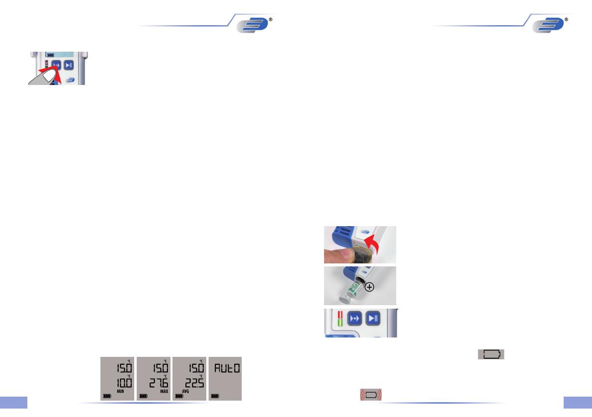
To replace the battery please open the battery cover
on the rear side. Therefore you have to turn the
battery cover 20° to the left. Use a coin to open/close
the battery lid.
Remove empty battery and insert new battery like
shown.
Battery change ok: both LEDs light for 1second, beep
sounds.
The empty battery symbol indicates that the battery needs to be replaced.
Device will only work correctly for 10 more hours.
The battery symbol indicates according to the battery status beween 0 and 3
segments.
If battery symbol is ashing, the battery is empty. The instrument does not
operate!
5.7.1 Special function of Mode-Button
5.7.1.1. Set marker
To mark special events during the record, markers can be set. Hit MODE key for 2.5
seconds until a short beep sounds (see mark on PDF Fig. C). The marker is stored
along with the next measurement (respect record interval!) .
5.7.1.2 Reset MAX-MIN buer
The logger has a MIN/MAX function to record extreme values for any period. Hit the
MODE key for 5 seconds, until a short melody sounds. This restarts the measurement
period. One possible use is the nding of day and night exterme temperatures. The
MIN/MAX function runs independent of data recording.
Please note:
- At start of record, the MIN/MAX/AVG buffer is also reset to show MIN/MAX/AVG
values that t the recording
- During recording, resetting the MIN/MAX/AVG buffer will force a marker.
5.7 Display Modes and Mode - Button: EXT, AVG, MIN, MAX
The rst line always shows the current measurement value
of the main meas channel: LOG200: Temperature, LOG210:
Humidity, LOG220: Air pressure, LOG200 TC/LOG210 TC:
External temperature 1, LOG200 E: Internal temperature,
LOG220 E: Internal air pressure. The second line display depends on the selected
mode. There are two display modes:
1. AUTO mode (default for LOG200, LOG210, LOG220) – the second line
shows alternating values each 3 seconds:
LOG200: Minimum(MIN), maximum(MAX) / average(AVG) of temperature
LOG210: Temperature and dewpoint
LOG220: Humidity, temperature and dewpoint
LOG200 TC: Internal temperature and external temperature 2
LOG210 TC:
Internal temperature, internal humidity, internal dewpoint and external temperature 2
LOG200 E:
current temperature Minimum (MIN), maximum (MAX) / average (AVG) of
temperature (extern) and Minimum (MIN), maximum (MAX) / average (AVG)
of temperature (intern)
LOG220 E:
current measurements of connected external sensors / current measurements
of internal humidity, temperature and dewpoint.
The displayed meas channel can be identied by the physical unit (°C/°F = tem-
perature, Td + °C/°F = dewpoint, %rH = humidity, hPa = air pressure, ppm=CO
2
)
along with the extension symbols <no symbol> = current measurement value,
MIN= Minimum, MAX= Maximum, AVG=average.
AUTO mode gives a quick overview on the current measurement values of all channels.
Pressing the MODE key (left key) leaves AUTO mode and enters MANUAL mode:
2. MANUAL
mode (default for LOG200 TC, LOG210 TC) – MODE key ips the second
line through all available measurement values, following the sequence current value (no symbol),
minimum (MIN), maximum (MAX), average (AVG). LOG200 TC and LOG210 TC show MIN,
MAX and AVG with a blinking EXT for external sensor 1 (main measurement channel) and a steady
EXT for external sensor 2.
MANUAL mode is handy to view any meas channel along with the main meas channel. Eg.
air pressure maximum vs. main channel air pressure. Hit MODE key until display shows AutO
to resume AUTO mode.
2928
5.9 Alerts
Beeper sounds once each 30 seconds for
1 second, red LED blinks each 3 seconds –
measured values exceeds selected alarm
settings(not with standard settings). Via Software
LogConnect alarm levels can be set.
If an alarm level has been occurred a X will be displayed on the display bottom.
On the corresponding PDF-report the alarm status will be indicated, too.
If the measurement channel is displayed where an alarm occurred the X on the right
bottom of the display is blinking.
The X disappears when the instrument has been restarted for recording!
Red LED blinks once each 4 seconds.
Replace battery.
Blinks twice or more each 4 sconds. Hardware
fault!
5.8.1 Set Date and Time after battery replacement via button
After battery replacement or power interrupt the instrument automatically changes
into the conguration mode to set date, time and interval. If no button will be pressed
for 20 seconds the unit proceeds with the last date and time in memory:
Press N=
No changing of date
and time, or Press
Y=Yes for changing
date and time
Press Mode-button to increase the value,
press Start-button for jumping to the next
value.
After date-time-request the Interval (INT) can
be changed.
Press N= No to
abort changes,
or Press
Y=Yes to
conrm changes
...
* Download free LogConnect software:
www.dostmann-electronic.de/home.html ->Downloads ->Software/<your logger>/
Software/LogConnect_XXX.zip (XXX choose latest version)
6. Technical data
Temperature
Measuring range: -40..+70°C
Resolution: 0.1°C
Pressure
only LOG220 /LOG220 E
Measuring range: 300-1100hPa
Resolution: 0.1 hPa
Memory:
LOG200: 150.000 measurements (Temp.+ motion)
LOG210: 100.000 data set (Temp., Humidity, dewpoint and motion)
LOG220: 60.000 data set
(Temp., Humidity, pressure, dewpoint and motion)
LOG200 TC: 60.000 measurements
(Temp.+ 2 external thermocouples T1, T2 + motion)
LOG210 TC: 60.000 measurements
(Temp., Humidity, dewpoint, + 2 external thermocouples
T1, T2 and motion)
LOG200 E: 100.000 measurements (Temp.+ motion)
LOG220 E: 60.000 measurements (Temp., Humidity, pressure, CO
2
dew point and motion)
Interface: USB (integr.)
Dimensions: 91.5 x 42 x 20 mm
Weight: Approx. 83 g, Incl. Wall holder
Battery: 1 x 3,6 Volt Lithium ½ AA
Note! After replacing the battery please check the correct time and date of
the internal clock. For setting the time see next chapter or 5.2.2.1 Conguration
software LogConnect.
6.1 Risk of injury:
Keep these devices and the batteries out of reach of children.
Batteries contain harmful acids and may be hazardous if swallowed. If a battery
is swallowed, this can lead to serious internal burns and death within two hours.
If you suspect a battery could have been swallowed or otherwise caught in the
body, seek medical help immediately.
Rel. Humidity
only
LOG210/LOG220/LOG210 TC/
LOG220 E
Measuring range: 0..100%rF
Resolution: 0.1%rF
CO
2
only LOG220 E
Measuring range: 400-10000 ppm
Resolution: 1 ppm
3130
10. Storage and cleaning
It should be stored at room temperature. For cleaning, use only a soft cotton cloth
with water or medical alcohol. Do not submerge any part of the thermometer.
This instrument is labelled in accordance with the EU Waste Electrical and
Electronic Equipment Directive (WEEE). Please do not dispose of this
instrument in household waste. The user is obligated to take end-of-life
devices to a designated collection point for the disposal of electrical and
electronic equipment, in order to ensure environmentally-compatible disposal.
9. Marking only LOG200
CE-conformity, EN 12830, EN 13485, Suitability for storage (S) and transportation
(T) for food storage and distribution (C), Accuracy classication 1 (-30..+70°C),
according to EN 13486 we recommend a recalibration once per year.
7. Explanation of symbols
This sign certies that the product meets the requirements of the EEC
directive and has been tested according to the specied test methods.
8. Waste disposal
This product has been manufactured using high-grade materials and components which can
be recycled and reused
Never dispose of empty batteries and rechargeable batteries in household
waste.
As a consumer, you are legally required to take them to your retail store or to an
appropriate collection site depending on national or local regulations in order to
protect the environment.
The symbols for the heavy metals contained are:
Cd=cadmium, Hg=mercury, Pb=lead
Table des matières
1. Introduction 32
2. Conseils / Consignes de sécurité 32
3. Contenu 32
4. Distribution et utilisation 32
5. Manipulation de l’appareil 33
5.1 Description de l’appareil 33
5.2 Fonctionnement de l’appareil 34
5.2.1 Installation standard à la livraison 34
5.2.1.1 Mode d’achage Power-Save 35
5.2.2 Logiciel Windows pour LOG200 35
5.2.2.1 Logiciel de conguration Log Connect 35
5.3 Premier démarrage & début d’enregistrement 35
5.3.1 Reprise l’enregistrement 36
5.3.2 Achage du lecteur de sauvegarde (en pour cent) 37
5.4 Arrêt d’enregistrement / génération du PDF 37
5.4.1 Arrêt d’enregistrement via le bouton ou la programmation 37
5.5 Interprétation du PDF (Fig. C) 38
5.6 Connexion USB 38
5.7 Modes d’affichage et touche de mode: EXT, AVG, MIN, MAX 39
5.7.1 Fonctions spéciales du bouton Mode 39
5.7.1.1Réglage du marqueur 39
5.7.1.2MAX-MIN-supprimer l’enregistrement 39
5.8 Changement de la batterie /
achage du niveau de la batterie 40
5.8.1 Réglage de la date/heure après le changement de la pile 42
5.9 Signal d’alarme 42
6. Données techniques 6.1 Danger de blessure 43
7. Dispositions générales / Légende 44
8. Entretien 44
9 Caractéristiques 44
10. Conservation & nettoyage 44
Batteries must not be thrown into a re, short-circuited, taken apart or recharged.
Risk of explosion!
• Low batteries should be changed as soon as possible to prevent damage caused
by leaking. Never use a combination of old and new batteries together, nor
batteries of different types.
Wear chemical-resistant protective gloves and safety glasses when handling
leaking batteries.
4746
Allumage rapide Avec les réglages par défaut
Commencer l’enregistrement:
Appuyer le bouton d’allumage,
jusqu’à l’émission du bip sonore
La luminodiode (LED) est verte
pendant 2 secondes, l’enregistrement
est déclenché. Le symbole RUN
apparaît
Attendre que l’enregistreur
soit connecté à
l’interface USB
attendre Présenter et
sécuriser le PDF
1. 2.
3. 4. 5.
Quick Start with default settings
Start Recording:
Press until beep sounds
LED lit green for 2 seconds
- recording started.
RUN icon appears
Insert logger into
USB port
wait View and
save PDF
1. 2.
3. 4. 5.
Technische Änderungen vorbehalten ● Nachdruck auch auszugsweise untersagt
Stand02 1903CHB ● © DOSTMANN electronic GmbH
Technical changes, any errors and misprints reservedReproduction is prohibited in whole or part
Stand02 1903CHB ● © DOSTMANN electronic GmbH
DOSTMANN electronic GmbH
Mess- und Steuertechnik
Waldenbergweg 3b
D-97877 Wertheim-Reicholzheim
Germany
Phone: +49 (0) 93 42 / 3 08 90
Internet: www.dostmann-electronic.de
Tous droits réservés ● Toute reproduction est interdite
Stand02 1903CHB ● © DOSTMANN electronic GmbH
  • Page 1 1
  • Page 2 2
  • Page 3 3
  • Page 4 4
  • Page 5 5
  • Page 6 6
  • Page 7 7
  • Page 8 8
  • Page 9 9
  • Page 10 10
  • Page 11 11
  • Page 12 12
  • Page 13 13
  • Page 14 14
  • Page 15 15
  • Page 16 16
  • Page 17 17
  • Page 18 18
  • Page 19 19
  • Page 20 20
  • Page 21 21
  • Page 22 22
  • Page 23 23
  • Page 24 24
  • Page 25 25

Dostmann 5005-0200 User manual

Category
Measuring & layout tools
Type
User manual

Ask a question and I''ll find the answer in the document

Finding information in a document is now easier with AI