Hilti TE 6-S Operating Instructions Manual
- Category
- Power tools
- Type
- Operating Instructions Manual

TE 6-S
Operating instructions en
Mode d’emploi fr
Manual de instrucciones es
Manual de instruções pt
Printed: 07.07.2013 | Doc-Nr: PUB / 5071103 / 000 / 00
Page is loading ...

Printed: 07.07.2013 | Doc-Nr: PUB / 5071103 / 000 / 00

2 3
4 5
6 7
8
Printed: 07.07.2013 | Doc-Nr: PUB / 5071103 / 000 / 00

9
10 11
12 13
14
Printed: 07.07.2013 | Doc-Nr: PUB / 5071103 / 000 / 00

1
en
It is essential that the operating
instructions are read before the
tool is operated for the first time.
Always keep these operating
instructions together with the tool.
Ensure that the operating instruc-
tions are with the tool when it is
given to other persons.
TE 6-S rotary hammer drill
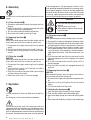
1. General information
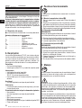
1.1 Indication of danger
-CAUTION-
This word is used to draw attention to a potentially dan-
gerous situation which could lead to minor personal injury
or damage to the equipment or other property .
1.2 Pictograms
Contents Page
1. General information 1
2. Technical data 2
3. General safety rules 2
4. Specific safety rules and symbols 5
5. Functional description 5
6. Assembly 6
7. Operation 6
8. Care and maintenance 7
9. Accessories 8
10. Manufacturer's warranty – tools 9
11. Disposal 10
12. Troubleshooting 10
Operating controls and components
Chuck
Function selection switch
On/off switch
Forwards/reverse switch
Side handle with depth gauge
Connection for the dust removal module
Supply cord
These numbers refer to the corresponding illustra-
tions. The illustrations can be found on the fold-out cov-
er pages. Keep these pages open while studying the oper-
ating instructions.
In these operating instructions, the designation "the tool"
always refers to the TE 6-S rotary hammer drill.
Location of identification data on the tool
The type designation and serial number can be found on
the type plate on the tool. Make a note of this data in your
operating instructions and always refer to it when mak-
ing an enquir y to your Hilti representative or ser vice
department.
Type:
Serial no.:
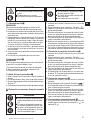
Warning signs
General
warning
Warning:
electricity
Warning:
hot surface
Obligation signs
Symbols
Wear eye
protection
Wear ear
protection
Wear protective
gloves
Read the operat-
ing instructions
before use.
Wear breathing
protection
ORIGINAL OPERATING INSTRUCTIONS
Printed: 07.07.2013 | Doc-Nr: PUB / 5071103 / 000 / 00

2
en
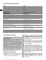
2. Technical data
Tool TE6-S
Rated power 650 W
Rated voltage 120 V
Rated current input 5.4 A
Mains frequency 50–60 Hz
Weight of tool 2.8 kg (6.3 lbs)
Dimensions (l×w×h) 320×215×75 mm (12.5×8.5×3.0″)
No load speed 0–1160 r.p.m.
Hammering speed (full hammering action) 0–5100 1/min.
Hammering speed (reduced hammering action) 0–2700 1/min.
Single impact energy (full hammering action) 1.8 Nm (J)
Single impact energy (reduced hammering action) 0.6 Nm (J)
Drilling dia. range in concrete/masonry
(hammer drill bits) 4–24 mm dia. (
3
/
16
″–1″ dia.)
Drilling dia. range in wood (wood drill bits) 5–20 mm dia. (
3
/
16
″–
3
/
4
″ dia.)
Drilling dia. range in wood (hole saws) 25–68 mm dia. (1″–2
5
/
8
″ dia.)
Drilling dia. range in metal (solid metal) 5–13 mm dia. (
3
/
16
″–
1
/
2
″ dia.)
Drilling dia. range in metal (sheet metal,
max. 2 mm [0.08″] thick) 5–22 mm dia. (
3
/
16
″–
7
/
8
″ dia.)
Drilling dia. range with thin-walled diamond core bits
(reduced hammering action) 25–68 mm dia. (1″–2
5
/
8
″ dia.)
Drilling performance in medium-hard concrete 8 mm dia. (
5
/
16
″ dia.) = 28 cm
3
/min.
12 mm dia. (
1
/
2
″ dia.) = 45 cm
3
/min.
16 mm dia. (
5
/
8
″ dia.) = 49 cm
3
/min.
Mechanical slip clutch ●
Vibration-absorbing grip and side handle ●
Right of technical modification reserved
3. General safety rules
SA VE THESE INSTRUCTIONS
3.1.1 Work area safety
a) Keep your work area clean and well lit. Clut-
tered or dark areas invite accidents.
b) Do not operate power tools in explosive atmos-
pheres, such as in the presence of flammable
liquids, gases, or dust. Power tools create
sparks which may ignite the dust or fumes.
c) Keep children and bystanders away while oper-
ating a power tool. Distractions can cause you to
lose control.
3.1.2 Electrical safety
a) Power tool plugs must match the outlet. Never
modify the plug in any way. Do not use any
adapter plugs with earthed (grounded) power
tools. Unmodified plugs and matching outlets will
reduce risk of electric shock.
3.1 General power tool safety warnings
WARNING! Read all safety warnings and all in-
structions. Failure to follow the warnings and
instructions may result in electric shock, fire and/or
serious injury . Save all warnings and instructions
for future reference. The term “power tool” in the
warnings refers to your mains-operated (corded)
power tool or battery-operated (cordless) power tool.
Printed: 07.07.2013 | Doc-Nr: PUB / 5071103 / 000 / 00

3
en
b) Avoid body contact with earthed or grounded
surfaces, such as pipes, radiators, ranges and
refrigerators. There is an increased risk of elec-
tric shock if your body is earthed or grounded.
c) Don’t expose power tools to rain or wet condi-
tions. Water entering a power tool will increase
the risk of electric shock.
d) Do not abuse the cord. Never use the cord for
carrying, pulling or unplugging the power tool.
Keep cord away from heat, oil, sharp edges or
moving parts. Damaged or entangled cords
increase the risk of electric shock.
e) When operating a power tool outdoors, use an
extension cord suitable for outdoor use. Use of
a cord suitable for outdoor use reduces the risk
of electric shock.
f) If operating a power tool in a damp location is
unavoidable, use a residual current device
(RCD) protected supply. Use of an RCD reduces
the risk of electric shock.
3.1.3 Personal safety
a) Stay alert, watch what you are doing and use
common sense when operating a power tool.
Do not use a power tool while you are tired or
under the influence of drugs, alcohol or med-
ication. A moment of inattention while operating
power tools may result in serious personal injury.
b) Use personal protective equipment. Always
wear eye protection. Protective equipment such
as dust mask, non-skid safety shoes, hard hat, or
hearing protection used for appropriate condi-
tions will reduce personal injuries.
c) Prevent unintentional starting. Ensure the
switch is in the off-position before connecting to
power source and/or battery pack, picking up or
carrying the tool. Carrying power tools with your
finger on the switch or energising power tools
that have the switch on invites accidents.
d) Remove any adjusting key or wrench before
turning the power tool on. A wrench or a key left
attached to a rotating part of the power tool may
result in personal injury.
e) Do not overreach. Keep proper footing and bal-
ance at all times. This enables better control of
the power tool in unexpected situations.
f) Dress properly. Do not wear loose clothing or
jewellery. Keep your hair, clothing and gloves
away from moving parts. Loose clothes, jew-
ellery or long hair can be caught in moving parts.
g) If devices are provided for the connection of
dust extraction and collection facilities, ensure
these are connected and properly used. Use of
dust collection can reduce dust-related hazards.
3.1.4 Power tool use and care
a) Do not force the power tool. Use the correct
power tool for your application. The correct
power tool will do the job better and safer at the
rate for which it was designed.
b) Do not use the power tool if the switch does not
turn it on and off. Any power tool that cannot be
controlled with the switch is dangerous and must
be repaired.
c) Disconnect the plug from the power source
and/or the battery pack from the power tool
before making any adjustments, changing
accessories, or storing power tools. Such pre-
ventive safety measures reduce the risk of start-
ing the power tool accidentally.
d) Store idle power tools out of the reach of chil-
dren and do not allow persons unfamiliar with
the power tool or these instructions to operate
the power tool. Power tools are dangerous in the
hands of untrained users.
e) Maintain power tools. Check for misalignment
or binding of moving parts, breakage of parts
and any other condition that may affect the pow-
er tool’s operation. If damaged, have the power
tool repaired before use. Many accidents are
caused by poorly maintained power tools.
f) Keep cutting tools sharp and clean.
Properly
maintained cutting tools with sharp cutting edges
are less likely to bind and are easier to control.
g)
Use the power tool, accessories and tool bits
etc. in accordance with these instructions, tak-
ing into account the working conditions and the
work to be performed. Use of the power tool for
operations different from those intended could
result in a hazardous situation.
3.1.5 Service
a) Have your power tool serviced by a qualified
repair person using only identical replacement
parts. This will ensure that the safety of the pow-
er tool is maintained.
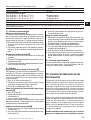
3.2 Additional safety instructions
3.2.1 Personal safety
a) Wear ear protectors. Exposure to noise can
cause hearing loss.
b) Use auxiliar y handles supplied with the tool.
Loss of control can cause personal injury.
c) Hold power tools by insulated gripping surfaces
when performing an operation where the cutting
tool may contact hidden wiring or its own cord.
Contact with a “live” wire will make exposed met-
al parts of the tool “live” and shock the operator.
Printed: 07.07.2013 | Doc-Nr: PUB / 5071103 / 000 / 00

4
en
d) Keep the grips dry, clean and free from oil and
grease.
e) Breathing protection must be worn if the power
tool is used without a dust removal system for
work that creates dust.
f) Improve the blood circulation in your fingers by
relaxing your hands and exercising your fingers
during breaks between working.
g) Avoid touching rotating parts. Switch the power
tool on only after bringing it into position at the
workpiece. Touching rotating parts, especially
rotating insert tools, may lead to injury.
h) Always lead the supply cord and extension cord
away from the power tool to the rear while
working. This helps to avoid tripping over the
cord while working.
i) When using the power tool for mixing, set the
function selector switch to “Hammer drilling”
and wear protective gloves.
j) Children must be instructed not to play with the
tool.
k) The tool is not intended for use by children,by
debilitated persons or those who have received
no instruction or training.
l) WARNING: Some dust created by grinding, sand-
ing, cutting and drilling contains chemicals
known to cause cancer, birth defects, infertility
or other reproductive harm; or serious and per-
manent respiratory or other injury. Some exam-
ples of these chemicals are: lead from leadbased
paints, crystalline silica from bricks, concrete and
other masonry products and natural stone, arsenic
and chromium from chemicallytreated lumber.
Your risk from these exposures varies, depending
on how often you do this type of work. To reduce
exposure to these chemicals, the operator and
bystanders should work in a well-ventilated
area, work with approved safety equipment,
such as respiratory protection appropriate for the
type of dust generated, and designed to filter out
microscopic particles and direct dust away from
the face and body. A void prolonged contact with
dust. Wear protective clothing and wash exposed
areas with soap and water. Allowing dust to get
into your mouth, eyes, or to remain on your skin
may promote absorption of harmful chemicals.
3.2.2 Power tool use and care
a) Secure the workpiece. Use clamps or a vice to
secure the workpiece. The workpiece is thus
held more securely than by hand and both hands
remain free to operate the power tool.
b) Check that the insert tools used are compatible
with the chuck system and that they are secured
in the chuck correctly.
3.2.3 Electrical safety
a) Before beginning work, check the working area
(e.g. using a metal detector) to ensure that no
concealed electric cables or gas and water
pipes are present. External metal parts of the
power tool may become live, for example, when
an electric cable is damaged accidentally. This
presents a serious risk of electric shock.
b) Check the power tool’s supply cord at regular
intervals and have it replaced by a qualified
specialist if found to be damaged. Check exten-
sion cords at regular intervals and replace them
if found to be damaged. Do not touch the supply
cord or extension cord if it is damaged while
working. Disconnect the supply cord plug from
the power outlet. Damaged supply cords or
extension cords present a risk of electric shock.
c) Dirty or dusty power tools which have been
used frequently for work on conductive materi-
als should be checked at regular intervals at a
Hilti Service Center. Under unfavorable circum-
stances, dampness or dust adhering to the sur-
face of the power tool, especially dust from con-
ductive materials, may present a risk of electric
shock.
d) When working outdoors with an electric tool
check to ensure that the tool is connected to the
electric supply by way of a ground fault circuit
interrupter (GFCI) with a rating of max. 30 mA
(tripping current). Use of a ground fault circuit
interrupter reduces the risk of electric shock.
e) Use of a ground fault circuit interrupter (GFCI)
with a maximum tripping current of 30 mA is
recommended.
3.2.4 Work area
a) Ensure that the workplace is well ventilated.
Exposure to dust at a poorly ventilated workplace
may result in damage to the health.
b) If the work involves breaking right through, take
the appropriate safety measures at the opposite
side. Parts breaking away could fall out and / or
fall down and injure other persons.
3.2.5 Personal protective equipment
The user and any other persons in the vicinity must
wear ANSI Z87.1-approved eye protection, a hard
hat, ear protection, protective gloves and breath-
ing protection while the power tool is in use.
Printed: 07.07.2013 | Doc-Nr: PUB / 5071103 / 000 / 00

5
en
4. Specific safety rules and symbols
4.1 Basic safety information
In addition to the safety precautions listed in the indi-
vidual sections of these operating instructions, the fol-
lowing points must be strictly observed at all times.
4.2 Correct use
The tools are designed for drilling in concrete, masonry ,
plasterboard, wood and metal.
The tools are designed for use on construction sites, in
workshops, for renovation, conversion and construction
work.
4.3 Incorrect use (misuse)
Operate the tool only when connected to a mains supply
with a voltage and frequency that complies with the infor -
mation given on the name plate.
Manipulation or modification of the tool is not permissi -
ble.
Observe the information printed in the operating instruc-
tions concerning operation, care and maintenance.
4.4 State of the art
● The tool is designed and manufactured according to
the state of the art.
● The tool and its ancillary equipment may present haz-
ards when used incorrectly by untrained personnel or
not as directed.
4.5 Proper arrangement and organisation of the
workplace
● Wear non-slip shoes and always work from a secure
stance.
● Avoid unfavourable body positions.
● Objects which could cause injury should be removed
from the working area.
4.6 General hazards presented by the tool
● Always hold the tool securely with both hands.
● Hold the side handle tightly at its farthest end.
● Never leave the tool unsupervised.
4.6.1 Electrical hazards
● When working outdoors, use only extension cords
that are approved and correspondingly marked for this
application.
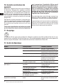
Extension Cord Table
Volts Total Length of Cord in Feet
120 V 0–25 26– 50 51–100 101–1 50
240 V 0–50 51–100 101–200 201–300
Ampere Rating A WG
More Than Not More Than
0 6 18 16 16 14
610 18161412
10 12 16 16 14 12
12 16 14 12 Not recommended
4.7 Requirements to be met by users
● The tool is intended for professional use.
Symbols used on the tool:
V ............................ volts
~ ............................ alternating current
Hz............................ hertz
A ............................ amperes
n
0
............................ no load speed
/min ............................ r evolu tio ns per min ute
∅ ............................ diameter
Z ............................ double insulated
5. Functional description
The TE 6-S rotary hammer drills with selectable pneu-
matic hammering mechanism are electrically-powered
tools for drilling in concrete, masonry , plasterboard (dry-
wall), wood, plastics and metal.
The tools are designed for professional use.
Chuck
– with rotary locking action
– Interface for TE-C chuck and keyless chuck
Switches
– Speed-control switch
– Function selection switch
TE6-S: 3 drilling functions
– Reversing switch (switch for forwards/reverse rotation)
Side handle
– Privoting side handle with depth gauge
Lubrication
– The gearing section and hammering mechanism fea-
ture permanent grease lubrication.
The items supplied as standard equipment include:
– Rotary hammer drill
– Privoting side handle with depth gauge
–Grease
– Operating instructions
– Toolbox
– DRS dust-removal module (with version in the pro-
fessional toolbox)
– Cleaning cloth
Printed: 07.07.2013 | Doc-Nr: PUB / 5071103 / 000 / 00

6
en
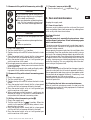
6. Assembly
The tool must not be connected to the electric mains
supply.
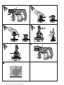
6.1 Fit the side handle
1. Release the side handle clamp by turning the side han-
dle grip.
2. Slide the side handle / clamping band over the chuck
onto the housing (clamping groove).
3. Turn the side handle into the desired position.
4. Secure the side handle by twisting its grip.
6.2 Removing the chuck
CAUTION
Remove the depth gauge from the side handle and the
insert tool from the chuck in order to avoid injury.
1. Disconnect the supply cord plug from the power
outlet.
2. Pull the chuck sleeve forward and hold it securely.
3. Remove the chuck by pulling it away from the pow-
er tool.
6.3 Fitting the chuck
CAUTION
Remove the depth gauge from the side handle and the
insert tool from the chuck in order to avoid injury.
1. Disconnect the supply cord plug from the power
outlet.
2. Grip the chuck sleeve, pull it for ward and hold it
securely in this position.
3. Slide the chuck onto the guide tube from the front
and then release the sleeve.
4. Rotate the chuck until it is heard to engage.
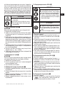
7. Operation
The side handle must always be fitted when the tool is in
use.
Use clamps or a vice to secure loose workpieces.
If extension cords are used: Only extension cords of a
type approved for the intended use and of adequate cross
section may be used. Failure to observe this point may
result in reduced performance of the tool and overheating
of the cord. Damaged extension cords must be replaced.
At low temperatures: The tool requires to reach a mini-
mum operating temperature before the hammering mech-
anism begins to operate. Switch on the tool and position
the tip of the drill bit on the work surface. While the tool
is running, apply light pressure briefly and repeatedly
until the hammering mechanism begins to operate.
-CAUTION-
■ The insert tool may become hot dur -
ing use.
■ You may burn your hands.
■ Wear protective gloves when chang-
ing insert tools.
7.1 Fitting the insert tool
CAUTION
Wear protective gloves when changing the insert tool.
1. Disconnect the supply cord plug from the power outlet.
2. Check that the connection end of the insert tool is clean
and lightly greased. Clean it and grease it if necessary .
3. Check that the sealing lip of the dust shield is clean
and in good condition. Clean the dust shield if neces-
sary or replace it if the sealing lip is found to be dam-
aged (please refer to the “Care and maintenance” sec-
tion).
4. Push the insert tool into the chuck and rotate it while
applying slight pressure until it engages in the guide
grooves.
5. Push the insert tool further into the chuck until it is
heard to engage.
6. Check that the insert tool has engaged correctly by
pulling it.
7.2 Removing the insert tool
CAUTION
Wear protective gloves when changing insert tools as
the insert tool will get hot during use.
1. Disconnect the supply cord plug from the power out-
let.
2. Open the chuck by pulling back the chuck release
sleeve.
3. Pull the insert tool out of the chuck.
7.3 Adjusting the depth gauge
1. Open the side handle clamp by turning the grip.
2. Pivot the side handle into the desired position.
3. Adjust the depth gauge to the desired drilling depth
"X".
4. Secure the side handle by turning the side handle grip.
Printed: 07.07.2013 | Doc-Nr: PUB / 5071103 / 000 / 00

7
en
-CAUTION-
■ The tool and the drilling operation emit
noise.
■ Excessive noise may damage the hear -
ing.
■ Wear ear protection.
-CAUTION-
■ The material may splinter during drilling.
■ Splintering material may injure parts
of the body and the eyes.
■ Wear eye protection, protective gloves
and, if a dust removal system is not
used, also wear breathing protection.
7.4 Hammer drilling with full hammering action
1. Plug in the supply cord.
2. Turn the switch to the "( )" position.
3. Position the tip of the drill bit where the hole is to be
drilled.
4. Press the control switch slowly (drill at a slow speed
until the drill bit has become centred in the hole).
5. Press the control switch as far as it will go when you
wish to continue at full speed.
6. Do not apply excessive pressure as this will not increase
hammering power. Lower pressure increases the life
of the insert tool.
7. When drilling a through hole, avoid spalling by reduc-
ing speed shortly before breaking through.
7.5 Hammer drilling with reduced hammering power
1. Plug in the supply cord.
2. Turn the switch to the ( ) position.
3. Position the tip of the drill bit where the hole is to be
drilled.
4. Press the control switch slowly (drill at a slow speed
until the drill bit has become centred in the hole).
5. Press the control switch as far as it will go when you
wish to continue at full speed.
6. When working on critical materials, spalling can be
reduced by using TE-C drill bits in new condition in
conjunction with reduced hammering action.
7.6 Drilling without hammering action
1. Plug in the supply cord.
2. Turn the switch to the "( )" position. When the
switch is in this position, only the rotary action is trans-
ferred to the insert tool.
3. Press the control switch slowly (drill at a slow speed
until the drill bit has become centred in the hole).
4. Press the control switch as far as it will go when you
wish to continue at full speed.
7.7 Forwards / reverse rotation
1. Turn the lever to the (L ) or position (R ).
8. Care and maintenance
Unplug the supply cord.
8.1 Care of insert tools
Remove any dirt adhering to the surface of the insert
tools and protect them from corrosion by rubbing them
with an oily cloth from time to time.
8.2 Care of the tool
CAUTION
Keep the power tool, especially its grip surfaces, clean
and free from oil and grease. Do not use cleaning agents
which contain silicone.
The outer casing of the power tool is made from impact-
resistant plastic. Sections of the grip are made from a
synthetic rubber material.
Never operate the power tool when the ventilation slots
are blocked. Clean the ventilation slots carefully using a
dry brush. Do not permit foreign objects to enter the inte-
rior of the power tool. Clean the outside of the power tool
at regular intervals with a slightly damp cloth. Do not use
a spray, steam pressure cleaning equipment or running
water for cleaning. This may negatively affect the elec-
trical safety of the power tool.
8.3 Maintenance
Check all external parts of the tool for damage at regular
intervals and check that all controls operate faultlessly.
Do not operate the tool when parts are damaged or when
the controls do not operate faultlessly . If necessary , have
the tool repaired at a Hilti service centre.
Electrical parts of the tool may be repaired only by trained
electrical specialists.
8.4 Checking the tool after care and maintenance
After all care and maintenance work, the tool must be
checked to ensure that all safety equipment is fitted and
that it operates faultlessly.
Printed: 07.07.2013 | Doc-Nr: PUB / 5071103 / 000 / 00

8
en
9. Insert tools and accessories
TE-C chuck ●
TE-C angular chuck ●
TE-AC 1 angular chuck ●
Hammer drill bits 4–24 mm dia. (
3
/
16
″–1″ dia.)
Bit holder ●
Thin-barrel core bits 25–68 mm dia. (1″–2
5
/
8
″ dia.)
Keyless chuck (quick release) ●
Drill bits for wood 5–20 mm dia. (
3
/
16
″–
3
/
4
″ dia.)
Drill bits for metal 5–13 mm dia. (
3
/
16
″–
1
/
2
″ dia.)
Stepped (stop) drill bits 5–22 mm dia. (
3
/
16
″–
5
/
8
″ dia.)
Hole saws 25–68 mm dia. (1″–2
5
/
8
″ dia.)
DRS dust removal module ●
9.1 DRS dust removal module
9.1.1 General information
Location of identification data on the tool
The type designation and serial number can be found on the type plate on the tool. Make a note of this data in your
operating instructions and always refer to it when making an enquiry to your Hilti representative or service depart-
ment.
Type: Serial no.:
9.1.2 Description
The DRS dust removal module is an accessory for the TE-6 rotary hammer drill. It can be attached to the rotary hammer
drill quickly and easily . The dust removal module is not suitable for chiselling work or for rotary drilling in metal.
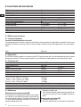
9.1.3 Technical data
Power input Max. 60 W
Suction performance 500 l/min
Weight 0.9 kg (2.03 lbs)
Maximum effective stroke 105 mm (4.1″)
TE-C hammer drill bit diameter range (It/cm): 4–16 mm dia. (
3
/
16
″–
5
/
8
″ dia.)
Drill bit working length 50–100 mm (2–4″)
Contact pressure 15–25 N
Dust container capacity
6mm(
1
/
4
″) dia. / 28 mm (1.1″) deep 130 holes
8mm(
5
/
16
″) dia. / 30 mm (1.2″) deep 75 holes
12 mm (
1
/
2
″) dia. / 50 mm (2″) deep 20 holes
Dust container regeneration cycles Up to 100 cycles
Extraction head 4–16 mm dia. (
3
/
16
″–
5
/
8
″ dia.)
Extraction fan, dust container with folded filter, depth gauge, length stop, plug-type connection
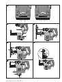
9.1.4 Before use
Attaching the dust removal module
The extraction fan incorporated in the dust removal mod-
uleisdrivenbythemotoroftherotaryhammerdrillby
way of a plug-type coupling. The teeth on the rotor shaft
(1) mesh with the teeth on the sleeve (2) of the dust
removal module drive shaft.
1. Unplug the supply cord.
2. Push the dust removal module along the guide (3) on
the rotary hammer drill until it engages securely in
place.
Removing the dust module
1. Unplug the supply cord.
2. Press the release latch (4) and hold it in this position.
Printed: 07.07.2013 | Doc-Nr: PUB / 5071103 / 000 / 00

9
en
3. Pull the dust module downwards away from the rotary
hammer drill.
9.1.5 Operation
Length adjustment (setting the stroke)
The stroke is normally set to TE-C drill bit I
t =150mm
(6″). This corresponds to an effective working length of
100 mm. The stroke must be adjusted if shorter drill bits
are used.
1. Open (A) the locking ring (5).
2. With the drill bit fitted in the chuck, press the tool
against the wall until the tip of the drill bit comes into
contact with the wall (C).
3. Close (B) the locking ring (5).
Setting the drilling depth (depth gauge)
1. Open (D) the end stop (6).
2. Slide the end stop to the desired drilling depth (F).
3. Close (E) the end stop (6).
When holes are to be drilled to a precise depth, e.g. for
setting anchors, the hole depth must be checked by drilling
test holes.
Changing the suction head
1. Pull back the rib (G) on the rear of the suction head
(7).
2. Pull the old suction head upwards out of the guide (H).
3. Press the new suction head into the guide until it
engages.
Emptying the dust container
1. Hold the tool horizontally and allow it to run for a short
time. This will cause any remaining dust particles in
the dust removal module to be sucked into the dust
container.
2. Press the button and hold it in this position (K).
3. Pull the dust container (8) downwards out of the dust
removal module (L).
4. Empty the dust container by tapping it lightly.
5. Slide the empty dust container into the dust module
from below until it engages in position. If you are insert-
ing a new dust container, remove the protective cov-
er before inserting it.
9.1.6 Care and maintenance
Use only compressed air and a cloth to clean the dust
removal module. Do not use water, oil, grease or clean-
ing agents.
10. Manufacturer's warranty – tools
Hilti warrants that the tool supplied is free of defects
in material and workmanship. This warranty is valid so
long as the tool is operated and handled correctly,
cleaned and serviced properly and in accordance with
the Hilti Operating Instructions, and the technical sys-
tem is maintained. This means that only original Hilti
consumables, components and spare parts may be
used in the tool.
This warranty provides the free-of-charge repair or
replacement of defective parts only over the entire lifes-
pan of the tool. Parts requiring repair or replacement
as a result of normal wear and tear are not covered by
this warranty.
Additional claims are excluded, unless stringent
national rules prohibit such exclusion. In particular,
Hilti is not obligated for direct, indirect, incidental
or consequential damages, losses or expenses in
connection with, or by reason of, the use of, or inabil-
ity to use the tool for any purpose. Implied warranties
of merchantability or fitness for a particular purpose
are specifically excluded.
For repair or replacement, send tool or related parts
immediately upon discovery of the defect to the address
of the local Hilti marketing organization provided.
This constitutes Hilti's entire obligation with regard to
warranty and supersedes all prior or contemporane-
ous comments and oral or written agreements con-
cerning warranties.
Printed: 07.07.2013 | Doc-Nr: PUB / 5071103 / 000 / 00

10
11. Disposal
Most of the materials from which Hilti power tools are manufactured can be recycled. The materials must be cor -
rectly separated before they can be recycled. In many countries, Hilti has already made arrangements for taking back
your old electric tools for recycling. Please ask your Hilti customer service department or Hilti sales representative
for further information.
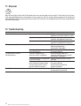
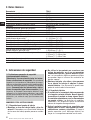
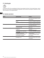
12. Troubleshooting
Fault Possible cause Remedy
The tool doesn’t start. No power from the mains supply. Plug in another electric tool or
appliance and check whether it works.
Supply cord or plug is defective. Have it checked by an electrical
specialist and replaced if necessary.
The control switch is defective. Have it checked by an elecrical
specialist and replaced if necessary.
No hammering action. The tool is too cold. Allow the tool to warm up to the
operating temperature
(see section “Operation”).
Function selection switch set to Set the function selection switch
rotary drilling only. to hammer drilling.
The tool doesn’t achieve The cross-section of the Use an extension cord with
full performance. extension cord is inadequate. adequate conductor cross-section
(see section “Operation”).
The control switch is not pressed Press the control switch as far as
as far as it will go. it will go.
The function selection switch is Set the function selection switch
set to reduced hamering action. to hammer drilling.
The reversing switch is set to Set the reversing switch to
counter -clockwise rotation. clockwise rotation.
The drill bit can’t be released. The chuck is not pulled back fully. Pull the chuck back as far as it will go
and remove the insert tool.
Printed: 07.07.2013 | Doc-Nr: PUB / 5071103 / 000 / 00
Page is loading ...
Page is loading ...
Page is loading ...
Page is loading ...
Page is loading ...
Page is loading ...
Page is loading ...
Page is loading ...
Page is loading ...
Page is loading ...
Page is loading ...
Page is loading ...
Page is loading ...
Page is loading ...
Page is loading ...
Page is loading ...
Page is loading ...
Page is loading ...
Page is loading ...
Page is loading ...
Page is loading ...
Page is loading ...
Page is loading ...
Page is loading ...
Page is loading ...
Page is loading ...
Page is loading ...
Page is loading ...
Page is loading ...
Page is loading ...

*369018*
369018
Hilti Corporation
LI-9494 Schaan
Tel.: +423 / 234 21 11
Fax: +423 / 234 29 65
www .hilti.com
Hilti = registered trademark of Hilti Corp., Schaan W 2628 1109 10-Pos. 3 1 Printed in China © 2009
Right of technical and programme changes reserved S. E. & O.
369018/ K
Printed: 07.07.2013 | Doc-Nr: PUB / 5071103 / 000 / 00
-
 1
1
-
 2
2
-
 3
3
-
 4
4
-
 5
5
-
 6
6
-
 7
7
-
 8
8
-
 9
9
-
 10
10
-
 11
11
-
 12
12
-
 13
13
-
 14
14
-
 15
15
-
 16
16
-
 17
17
-
 18
18
-
 19
19
-
 20
20
-
 21
21
-
 22
22
-
 23
23
-
 24
24
-
 25
25
-
 26
26
-
 27
27
-
 28
28
-
 29
29
-
 30
30
-
 31
31
-
 32
32
-
 33
33
-
 34
34
-
 35
35
-
 36
36
-
 37
37
-
 38
38
-
 39
39
-
 40
40
-
 41
41
-
 42
42
-
 43
43
-
 44
44
-
 45
45
-
 46
46


Hilti TE 6-S Operating Instructions Manual
- Category
- Power tools
- Type
- Operating Instructions Manual
Ask a question and I''ll find the answer in the document
Finding information in a document is now easier with AI
in other languages
- français: Hilti TE 6-S
- español: Hilti TE 6-S
- português: Hilti TE 6-S
Related papers
-
Hilti TE 2-S User manual
-
-
-
-
-
-
-
-
-
Other documents
-
Skil 6950 AD Owner's manual
-
Festool 1400 EQ User manual
-
Parkside PBHA 12 A1 Translation Of The Original Instructions
-
Black & Decker KR750 User manual
-
Ega Master 79330 Owner's manual
-
-
General Pipe Cleaners D-25-2-A Installation guide
-
Makita XRH01ZVX User manual
-
Parkside PBH 1050 C3 Original Instructions Manual
-
Husqvarna DS 40 Gyro ES PT GB GR User manual